Abstract
The development of modern rotating machines requires design of effective defect diagnostics methods for evaluation of technical conditions not only for the entire rotating system, but for each damaged element, e.g. journal and antifriction bearings, couplings, gears, etc. Optimization of rotating system goes through theoretical modeling based on FEM, bond graph theory, prototyping and experimental vibration testing rotating kits in labs and machines in situ. Nodal defects must be observed in early stage of their development. This article presents faults diagnostic for the vertically and horizontally oriented rotor rolling bearings. Studies were carried out at the original research setup. The research stand is composed of a rotor with a disc with the excitation mass fixed on it, rotor, driven by asynchronous AC motor controlled by frequency inverter. Rotor mounted in supports using single row deep groove ball bearings SKF 6004 – 2Z, class C3. During the research, the second non defected rolling bearing was replaced with rolling bearing with inner and outer ring race defects. Experiments were performed by changing the rotor axis of rotation from vertical to horizontal. Experiments were carried out with permissible imbalance (according to ISO 1940-1) and with more than 2 times higher than permissible, assessing the level of allowable imbalance magnitude, according to standard G6.3 class for rotary systems with flywheel impeller. Measurements of mechanical vibration acceleration are taken with 4 acceleration transducers, mounted on each of the supports. This article is focused on analyzing the second support direction (gravity direction) transducer data: velocity spectrums, waterfall plots and cascades. Analysis of horizontally and vertically oriented rotor dynamics, characteristics of diagnostics and statistical analysis of measurement data was performed. New statistical parameter, “Defect visibility ratio (DVR)” was presented. This parameter helps in quantifiably assessing the influence of excitation characteristics of differently oriented rotors to dynamics diagnostics. The statements listed in conclusions are formulated according to results obtained during experiments only.
1. Introduction
Rotating machinery with horizontal rotor axis is more widespread in the industry. For this reason, most of the scientific articles focus on the monitoring of the horizontal rotation axis machinery condition and fault diagnostics through vibration measurements. There is less data on vibration monitoring and fault diagnostics available in research materials, as vertical rotation axis machines are used relatively less frequently in industry. Comparing mechanisms with horizontal rotating axis, to ones with vertical rotation axis, the greatest difference in design is in their radial and axial bearing supports. Some scientists carried out rotor system researches with deep groove ball bearing diagnostics. The studies focused on a new way of vibration data statistical spectrum and cascade processing methods [1, 2]. Many papers studied different defects of deep groove ball bearings using analytical models and FEM [3, 4]. Valuable data is given on the fault development of rolling element bearings and their diagnostics [5, 6]. Flexible vertical rotor modeling and failure diagnostics with experimental testing in situ is presented in [7]. This data suggests more efficient ways in providing condition monitoring and prediction of unexpected failures in rotor systems with deep groove ball bearings. Articles [8, 9] focus on problems related to radial gap failure diagnostics of rolling bearings. Chaotic kinematics of rotors with roller bearings, including nonlinearities as radial gaps, increase vibration levels in high order harmonics. This makes the defect diagnostics of bearings difficult in the early stage of development [10, 11]. The scientific works, which are intended to analyze rotor systems with vertical axis of rotation are dedicated to analyze dynamics of these systems and anisotropy of rotor supports, but not intended to researches development of rolling bearings diagnostics. Reviewed papers focus on improving the rotor with rolling bearings failures diagnostics and show that less attention is paid to specify diagnostic features of vertical rotation axis rotors [13, 14, 15].
The task of this paper is to evaluate the quantitative differences in horizontal versus vertical axis rotors running on damaged roller bearings, through the use of mechanical vibration measurements.
2. The experimental setup
The experimental test kit, shown in Fig. 1, has been set up in order to investigate failure diagnostic differences testing a damaged 6004-2Z/C3 P6 single row deep groove ball and new bearings in horizontal and vertical axis rotors. The rotor is driven by a variable-speed AC motor controlled by a current frequency converter. Rotational speed during measurement has been changed from 100 to 3050 r/min. The rotor bearing supports 1 and 2 were mounted in 50 mm, 550 mm distances from flywheel disc. The rotation axis of the rotor kit has been switched from horizontal to vertical position. At first, the brand new 2nd ball bearing was tested and then, it has been replaced with the defected bearing. Separate tests were provided: the first one with artificial defect on the inner ring race and second – with artificial defect on the outer ring race, as shown in Fig. 3. In order to evaluate the vibration severity of the rotor, variable imbalance was used. Tests were carried out with minimum imbalance of 27 g mm (maximum permissible imbalance is 125 g mm) and with determined residual imbalance of 300 g mm as found in balancing quality grade G6.3 (ISO 1940-1). The balancing mass was attached to the rotor flywheel disc at radius . The absolute vibration velocity of bearing supports has been measured with four accelerometers 1xa, 1ya and 2xa, 2ya mounted in two perpendicular directions at each bearing support. Experimental data has been processed using multi-channel vibration signal analyzer "OROS".
As shown in Table 1, the damaged bearings with defects of inner and outer rings races, kinematic vibration frequencies were simulated. Constant rotational speed of inner ring 3050 r/min and outer ring was fixed: ball diameter 6,35 mm, number of balls 9.
Table 1Kinematic vibration frequencies with stationary outer ring for the bearing SKF 6004–2Z/C3 P6
Constant rotation speed of inner ring, 3050 r/min 50,83 Hz and outer ring 0 r/min | Typical vibration frequencies, Hz |
Rotational frequency of rolling element cage | 20,2 |
Vibration caused by radial fault of the rolling element, with consideration to its impacts only against the inner or only against the outer ring [Hz] | 119 |
The passage of rolling elements over defect in the rotating inner ring | 276 |
The passage of rolling elements over defect in the stationary outer ring | 182 |
Vibration caused by radial fault of the rolling element, with consideration to its impacts against the inner and outer rings [Hz] | 238 |
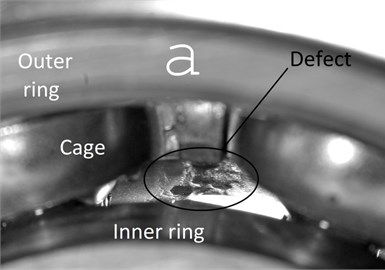
The races defects of the bearing’s inner and outer rings were formed artificially as shown in Fig. 2. The stationary mode measurements were performed at a constant rotational speed of 3050 r/min with residual imbalance of 300 g mm and a permissible imbalance of 27 g mm.
The permissible imbalance was chosen in order for the rotating system to generate valuable inertia force to act on the testing bearings. Maximum permissible imbalance for rotors of such kind is 125 g mm and calculated according to ISO 1940-1 rotor’s imbalance grade G 6.3:
where G 6.3 – balance quality grade 6,3 mm/s; 6,35 kg – mass of the rotor; 3050 r/min – constant rotational speed.
Fig. 1Test kit of the vertically positioning rotor axis with vibration accelerometers: 1xa, 1ya and 2xa, 2ya
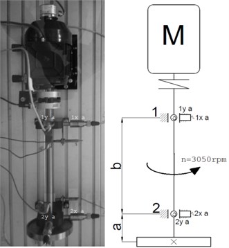
Table 2The vibration measurements order
No. | Orientation of rotor axis | Imbalance | Rolling bearing defects |
1. | Horizontal | 27 g∙mm | Without |
Vertical | |||
2. | Horizontal | 300 g∙mm | Without |
Vertical | |||
3. | Horizontal | 27 g∙mm | Inner ring race defect |
Vertical | |||
4. | Horizontal | 300 g∙mm | Inner ring race defect |
Vertical | |||
5. | Horizontal | 27 g∙mm | Outer ring race defect |
Vertical | |||
6. | Horizontal | 300 g∙mm | Outer ring race defect |
Vertical |
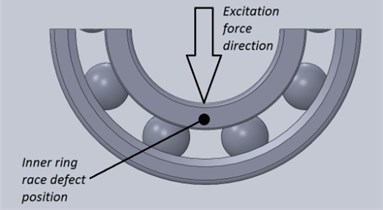
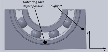
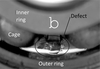
Fig. 2Initial measurement conditions: a) position of inner ring race defect; b) position of outer ring race defect
a)
b)
The rotor vibration severity evaluation for the horizontal and vertical rotation axis was provided according to different technical conditions, as shown in Table 2. Initial measurement conditions: the excitation force direction was the same as that of the inner ring race defect, when researching the inner ring race defect, shown in Fig. 2(a). Researching the bearing with outer ring race defect, the ring with defect was mounted in direction shown in Fig. 2(b).
Fig. 3Defects of the deep groove ball bearing 6204 2Z/C3 P6: a) inner ring race defect, b) outer ring race defect
a)
b)
3. The results and analysis of vibration measurement data
The absolute vibration velocities data for the rotor bearing supports was evaluated as root mean square values and vibration velocity spectrum and cascade diagrams. The 2nd bearing was examined. The first test was performed with the brand new 2nd bearing and the second and third test has been carried out with the faulty 2nd bearing. The 1st bearing was brand new throughout the entire experiment.
The 2nd bearing support vibration measurement data plotted in vibration velocity spectral cascade diagrams (Fig. 4 and 5) shows that the 1X frequency vibration magnitudes dominated in horizontal axis rotor at run up mode at wide rotational speed range (1000-3050 r/min). However, the vertical axis of rotor with the new bearing generates 1X, 2X, 3X harmonics at wide rotational speed range and indicated existence of radial gaps as nonlinearities (Fig. 4b). Therefore, it is difficult to diagnose imbalance in such systems. The vertical axis rotor with damaged bearing generates 1X, 2X, …, 7X frequencies vibration harmonics from 1500 r/min (Fig. 5b). This shows that it is difficult to diagnose the imbalance in the rotor with significant defect in bearing. The nonlinearities of radial gaps in the bearings dominated without acting gravity force as shock form.
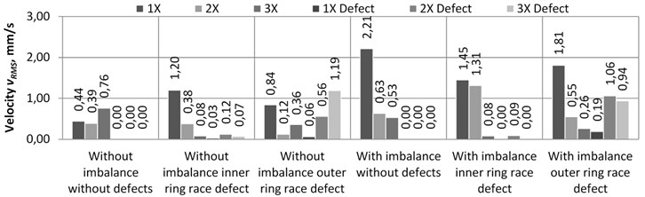
Stationary mode at 3050 r/min was analyzed using vibration velocity root mean square values, as shown in (Fig. 8, 9, 10 and 11). The statistical analysis of measurements taken at vertical axis rotor shows that the 2nd bearing support stiffness in -direction is lower than the stiffness in -direction (determined using FEM). Also it is determined that due to additional imbalance of 300 g mm, in comparison to measurements with permissible imbalance, the vibration velocity level of 1X harmonic increases from 10 % to 40 %, while the vibration velocity values of rolling bearing defect frequency increase by only 10-15 %.
The vibration velocity cascades presented in Fig. 4 show that measured level of vibrations for the vertical axis rotor introduces vibration noise values around the bearing defect frequency. This effect complicates diagnostics of the vertical rotor bearings, because these vibrations might cause rubbing of chain drives, shaft alignment inaccuracies, coupling defect and etc.
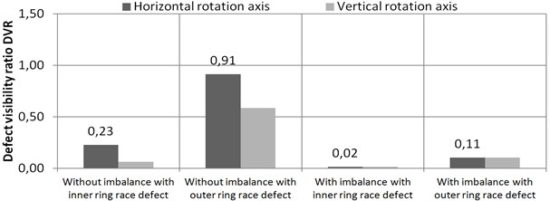
The comparison data of statistical vibration velocity values is shown in the diagrams of Figures 8, 9, 10, 11. The values of horizontally oriented rotor vibration dominated. The values in the -direction were about 2 times higher in the horizontal axis rotor, than one in the vertically oriented rotor, but the simulated stiffness of supports was about two times higher in direction than in -direction. The physical effect stated that the rotor’s gravity force augments vibrations velocity values in horizontally oriented rotor, although the anisotropy of supports is significantly noticeable and stiffness of supports in -direction is higher than in -direction. “Defect visibility ratio (DVR)” parameter was designed for the quantitative evaluation of the dynamics features of the vertical and horizontal rotors with deep grove ball bearings:
where: – dominant defect nX harmonic vibration velocity value, mm/s;
– 1X frequency vibration velocity value, mm/s.
Fig. 4Vibration velocity vRMS cascade plots of 2nd new 6004 2Z/C3 bearing measured with 2ya accelerometer, at run up mode of the rotor 300 g·mm unbalance: a) horizontal axis rotor; b) vertical axis rotor
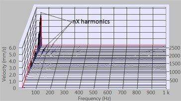
a)
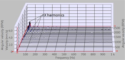
b)
Fig. 5Vibration velocity vRMS cascade plots of 2nd defect bearing 6204 2Z/C3 with outer ring race defect measured with 2ya accelerometer, at run up mode of the rotor with 300 g·mm imbalance: a) horizontal axis rotor, b) vertical axis rotor
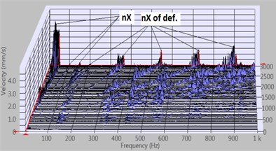
a)
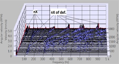
b)
Fig. 6Vibration velocity vRMS spectrum plot of 2nd defect bearing 6204 2Z/C3 with inner ring race fault measured using 2ya accelerometer, horizontal axis rotor
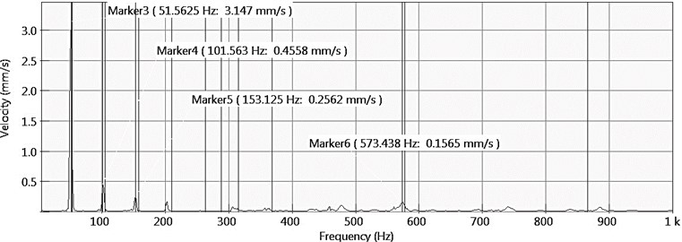
Fig. 7Vibration velocity vRMS spectrum plot of 2nd defect bearing 6204 2Z/C3 with inner ring race fault measured using 2ya accelerometer, vertical axis rotor
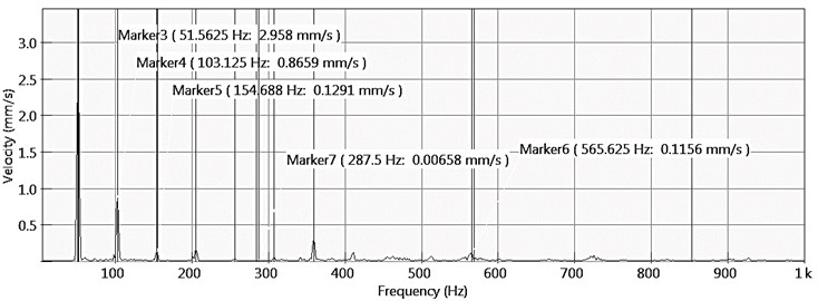
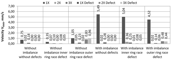
Fig. 8. Vibration velocity values diagram of the horizontally oriented rotors 2ya accelerometer
Fig. 9Vibration velocity vRMS values diagram of the vertically oriented rotors 2ya accelerometer
The statistical data of dominating faulty bearing vibration velocity level value divided by 1X harmonic vibration velocity level values were presented in Fig. 12, 13 DVR diagrams. The graphs show, that, in some cases, when the rotor is oriented vertically, the bearing fault frequency vibration velocity level is very low, compared to 1X harmonic vibration velocity level. It complicates diagnostics for such rotors.
The vibration velocity cascade presented in Fig. 6, 7 shows, that in some cases the vertical rotor measured vibration level has a great deal of vibration noise around the bearing defect frequency. It complicates rotor bearing diagnostics, because these vibrations can be triggered by work chain rubbing, shaft alignment, coupling defect and etc.
Fig. 10Vibration velocity vRMS value diagram of the horizontally oriented rotors 2xa accelerometer
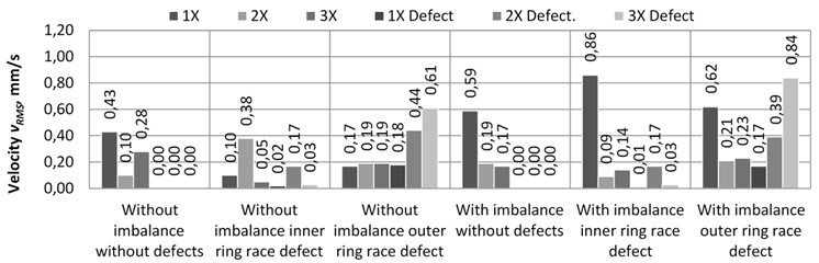
Fig. 11Vibration velocity vRMS value diagram of the vertically oriented rotors 2xa accelerometer
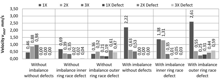
Fig. 12Horizontally and vertically oriented rotors “Defect Visibility Ratio” calculated from 2xa accelerometer measurement data
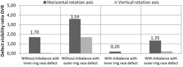
Fig. 13Horizontally and vertically oriented rotors “Defect Visibility Ratio” calculated from 2ya accelerometer measurement data
The data obtained by measuring the vibration velocity of the first support (the second plane data) allows only a partial determination of the second support bearing faults. When faulty rolling bearing with inner ring race defect was mounted on 2nd support, in second plane (1st support plane) kinematic bearing fault frequency harmonics cannot be detected. However, when faulty bearing with outer ring race defect was mounted on 2nd support, the accelerometers mounted on 1st support (second plane accelerometers) captured a relatively high level of the outer ring race defect frequency 2× and 3× harmonics, shown in Fig. 14 and 15 charts.
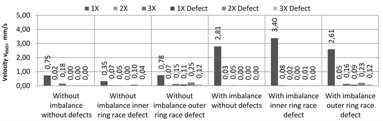
Fig. 14. Vibration velocity value diagram for the horizontally oriented rotors 1ya
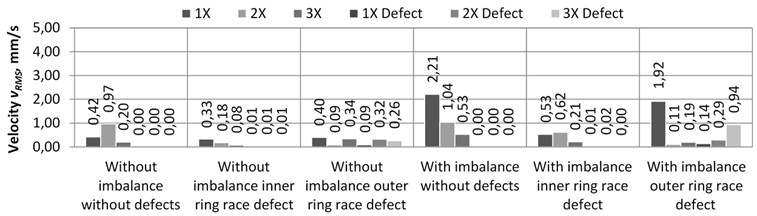
Fig. 15. Vibration velocity value diagram for the vertically oriented rotors 1ya
4. Conclusions
1. Vibration velocity spectrums of the vertical rotor are rich in higher level vibrations as well as they have a higher order of harmonics compared to horizontal axis rotors. This is due to the chaotic vertical rotor movement kinematics in radial bearing clearance.
2. Vibration intensity of horizontal axis rotor is higher in comparison to vertical axis rotor in -direction due to gravitational influence to horizontal rotor in radial -direction. Horizontal rotation axis rotor is more sensitive to imbalance that generates high level 1X frequency vibration amplitudes in comparison to the vertical axis rotors that are more sensitive to the values of radial gaps in the bearings.
3. The designed DVR values provide quantitative evaluation of horizontal and vertical rotors vibration ratio levels that enable the determination on how many times the defect frequency band vibration level is less than the first harmonic vibration level. It quantifies the complexity of the defect diagnosis.
4. Horizontal axis rotor is more sensitive to damaged bearing elements. That facilitates the determination of such rotor bearing defects in early stages of development. Diagnostics of vertically oriented rotors are more complicated. Imbalance has a greater influence to diagnostics of vertical rotor systems (due to imbalance DVR value of vertical rotor with inner ring race fault and imbalance is lower).
5. The rolling bearings with artificially developed defects were used in this research. The rolling bearing kinematic frequencies were calculated for the bearing with one rolling element defect. Naturally, multiple defects mostly develop at the same time. To determine rolling bearing defects in early stage of development it is necessary to pay attention to the bearing kinematic frequencies sub-harmonics vibration levels, they help to separate vibration levels in higher harmonics.
References
-
Tuncay Karacay, Nizami Akturk Experimental diagnostics of ball bearings using statistical and spectral methods. Tribology International, Vol. 42, 2009, p. 836-843.
-
Rujiang Hao, Fulei Chu Morphological undecimated wavelet decomposition for fault diagnostics of rolling element bearings. Journal of Sound and Vibration, Vol. 320, 2009, p. 1164-1177.
-
Bo Taoa, Limin Zhub, Han Dinga, Youlun Xionga An alternative time-domain index for condition monitoring of rolling element bearings – a comparison study. Reliability Engineering and System Safety, Vol. 92, 2007, p. 660-670.
-
Zeki Kiral, Hira Karagulle Vibration analysis of rolling element bearings with various defects under the action of an unbalanced force. Mechanical Systems and Signal Processing, Vol. 20, 2006, p. 1967-1991.
-
Robert B. Randall, Jerome Antoni Rolling element bearing diagnostics – a tutorial. Mechanical Systems and Signal Processing, Vol. 25, 2011, p. 485-520.
-
Sedat Karabay, Ibrahim Uzman Importance of early detection of maintenance problems in rotating machines in management of plants: case studies from wire and tyre plants. Engineering Failure Analysis, Vol. 16, 2009, p. 212-224.
-
V. Barzdaitis, R. Jonušas, Z. Pocius, V. Žemaitis Flexible vertical rotor modeling and dynamics. Mechanika, Vol. 33, 2002, p. 35-41.
-
Ehrich F. High-order subharmonic response of high speed rotors in bearing clearance. Journal of Vibration, Acoustics, Stress and Reliability in Design – Transactions of the ASME, Vol. 110, 1988, p. 9-16.
-
P. Goldman, A. Muszynska Dynamic effects in mechanical structures with gaps and impacting: order and chaos. Journal of Vibration and Acoustics, Vol. 116, 1994, p. 541-547.
-
Mevel B., Guyader J. L. Routes to chaos in ball bearings. Journal of Sound and Vibration, Vol. 162, 1993, p. 471-487.
-
R. B. Randall, Y. Gao Masking effects in digital envelope analysis of faulty bearing signals. Sixth International Conference on Vibrations in Rotating Machinery, IMECHE, Oxford, 1996, p. 351-359.
-
R. B. Randall, J. Antoni, S. Chobsaard The relationship between spectral correlation and envelope analysis in the diagnostics of bearing faults and other cyclostationary machine signals. Mechanical Systems and Signal Processing, Vol. 15, Issue 5, 2001, p. 945-962.
-
A. Muszynska Forward and backward precession of a vertical anisotropically supported rotor. Journal of Sound and Vibration, Vol. 192, 1996, p. 207-222.
-
G. Genta Dynamics of Rotating Systems. New York, Springer, 2005.
-
H. Dresig, F. Holzweißig Dynamics of Machinery. Theory and Applications. London, New York, Springer, 2010.
About this article

