Abstract
The paper presents an analysis of elastic-plastic stability of sandwich conical shells with a change in the thickness of face-layers. The shells under consideration consist of two load-carrying face-layers and a lightweight core layer. The thickness of those faces may vary, just as their material properties. The load carrying faces are made of isotropic, compressible, work-hardening materials. The core layer is assumed to be elastic, incompressible in the normal direction and it resists transverse shear only. External load is assumed to be in the form of longitudinal force and lateral pressure. Deformation of the shells within the plastic range is possible before buckling. With respect to the presented research, constitutive relations of the Nadai-Hencky deformation theory, alongside the H-M-H (Huber-Mises-Hencky) yield condition constitutive relations, are accepted in the analysis. To derive the stability equations a variation, strain energy method is accepted and the Ritz method has been used to solve the stability equations.
1. Introduction
Thin-walled sandwich shells have high structural efficiency and they are very interesting from the point of view of the design. Those structures are more often used to design various structures (e.g. aerospace, buildings. vehicles, tanks) and, therefore, these are well recognized in the scientific literature [1, 2]. There are many advantages of such structures. The main advantage of such structures is the load-to-weight ratio which is comparatively high. Other important qualities which characterize those structures, such as thermal, acoustic and vibroisolation properties can be specified. The conical shell elements are often used in some kind of technical structures (e.g. plane and aerospace fuselage, train bodies). Therefore, in particular applications, a sandwich conical shell element under combined external loads may provide for interesting case studies. Stability of cylindrical and conical shells is considered by many authors. During the last years appreciable development of theoretical and analytical methods has been observed. Research works refer to single-layer shells [3-11], whereas fewer studies dwell on bi-layered [12, 13] and sandwich shells [14-17]. In Refs. [1, 2, 6], both linear and nonlinear buckling analyses of elastic-plastic conical and cylindrical shells have been presented. Various methods of sandwich structures analysis are presented in Ref. [18] and a large reference list is given there. Some particular aspects of inelastic buckling of layered conical and cylindrical shells are described in Refs. [12, 15, 16]. The buckling of a dynamic load elastic truncated conical shell is presented in Ref. [10]. Some empirical results concerning conical shells subjected to external uniform pressure are presented in Ref. [7]. In Refs. [3-5, 11] an analysis of conical shells under various loading is presented. The review of the literature, as presented, shows that there are not many publications dealing with stability of sandwich conical shells, particularly ones with various face-layers thicknesses, subjected to two parametrical loads. This paper is dealing with this issue. An analysis of the stability paths of sandwich conical shells under combined loading (Fig. 1), particularly with a change in the thickness of face-layers is the main objective of this paper.
2. Basic assumptions
Several assumptions must be accepted at first. The analyzed object is a sandwich conical shell element. The shell consists of two thin face-layers and one core layer (Fig. 2). The face-layers may be of different thicknesses and can be made of different materials which are compressible and isotropic. The geometrically nonlinear theory and elastic-plastic properties of the faces are taken into account. The core layer is made of lightweight material and is assumed to be elastic, incompressible in the normal direction and it resists transverse shear only. The middle surface of the core layer is taken as the reference surface of the shell.
Fig. 1The model of the shell and external loads under consideration
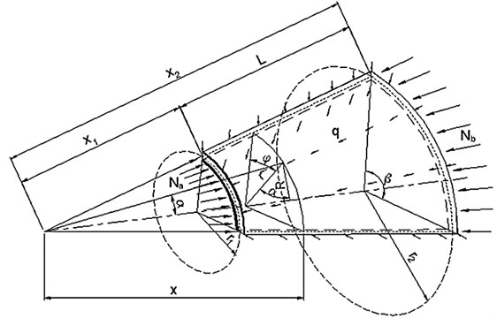
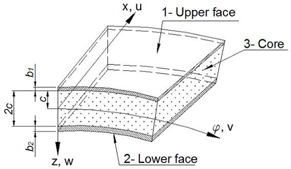
Fig. 2. The shell layers with the coordinate system
The other main assumptions, which have been taken with respect to the accepted model, are as follows:
– the shell is shallow and thin-layered,
– the general theory of thin-layered shells is obligatory,
– the Kirchhoff-Love hypothesis is valid within the entire cross-section of the shell,
– the post-buckling stress state is elastic, elastic-plastic or plastic,
– the displacement in normal z direction does not depend on the coordinate,
– the prebuckling stress state is the membrane one,
– the constitutive relations in the analysis are those of the Nadai-Hencky deformation theory with the H-M-H yield condition,
– the bilinear stress-strain relation for the face-layers is accepted,
– the considered shell has no imperfections.
3. Loading and stresses
There are two different types of loads acting on the shell under consideration. The first one is the longitudinal forces , applied at the edges of the shell and the second one is the surface pressure directed perpendicularly to the shell main surface (Fig. 1). According to the main assumptions, there is a membrane prebuckling stress state in the shell with the following internal forces:
The parameter , which represents the ratio between the lateral and longitudinal load is introduced:
The stresses in the pre-buckling state of stress can be expressed by the external forces in the following way:
In agreement with the main assumptions, the effective stress in the shell faces can exceed the yield stresses for the materials of these faces. When this occurs, appropriate plasticity theory relations have to be used. The constitutive relations of the Nadai-Hencky deformation theory are used to obtain stability equations in this work. The basic form of the equations of this plasticity theory is as follows:
where: is average stress, is the Kronecker delta, , are the elastic and plastic material constants.
Following Eq. (4), the two terms in the constitutive relations – the elastic and plastic ones could be separated. Inverting these relationships, the stresses can be expressed by strains [1]:
The resultant middle surface forces and moments in the shell faces are defined as follows:
where: – the stress indication and for the upper and lower face respectively.
The internal forces and moments developed by buckling are derived by integration of Eq. (6). The resulting relations, as obtained, are rather complicated. Having made some simplifications, these relations can be described in a matrix form as follows:
where 1 for the upper face-layer, 2 for the lower face-layer.
The coefficients in Eqs. (7) are the local stiffnesses that follow the Nadai-Hencky deformation theory of plasticity. Their forms are quite extensive and have not been presented here thoroughly.
4. Displacements and strains
The main assumptions enable using of the well-known “broken line” hypothesis to describe the geometrical relations between the displacement components: , , of the arbitrary point of the shell and the displacements of the points on the middle surfaces of the specific faces , , , (Fig. 3).
Fig. 3The displacements of the sandwich shell element
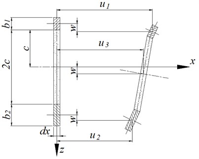
Separately for each layer, we can describe the displacements for the arbitrary points of the shell:
– the upper face-layer :
– the core-layer :
– the lower face-layer :
where , , , are relations between displacements of the points on the middle surfaces of the specific faces [1, 2]:
The strains and changes in curvature are expressed depending on the displacements as described above, using non-linear geometrical relations [1]:
where 1 for the upper face, 2 for the lower face.
5. Potential energy in the shell and stability equation
A set of the stability equations, expressed by the displacements does not have an explicite solution. The virtual work principle and the strain energy methods comprise a basis for obtaining equilibrium equations for the considered shell. As far as a sandwich shell, the total strain energy is the sum of the strain energy of the specified layers. If the potential of external loads is represented by we have the following relations:
where the particular superscripts are related to the shell layers: (1), (2) – the face layers, (3) – the core layer.
The terms in Eq. (13) related with the strain energy are [1]:
where 1 for the upper face, 2 for the lower face.
The work of external forces is connected with the lateral pressure and longitudinal forces acting upon the shell. The potential of external loads is given by:
According to the assumptions, the considered shell is free supported. Appropriate displacement functions must be accepted. The displacements functions must satisfy the boundary conditions concerning the shell under consideration: deflections at the edges of the shell are equal to zero, there are no displacements along the supports and there are no relative displacements of the both layers of the shell at the edges:
Bearing in mind the above conditions the following displacements functions are accepted [1, 16]:
where are free parameters to be determined, , are constants.
Using the above displacement relations in the non-linear geometrical relations in Eqs. (8-10), and, subsequently, in Eq. (13), the full description of the shell potential energy is obtained. The next step is to apply the Ritz method which requires that the partial derivatives of the total potential energy of the shell with respect to parameters is zero. Finally, we obtain a set of algebraic equations for the considered shell whose general matrix form is as follows:
where are coefficients of the set of equations which depend on geometrical parameters of the shell, physical properties, buckling form, and external loading.
The set of equations Eqs. (18) solved with respect to the free parameter of the deflection function Eqn. (17), and following some transformations and simplifications, provides the final solution in the form of a non-linear algebraic equation:
where are coefficients of the stability equation which are very complicated in form and depend on the geometrical parameters, physical properties, buckling form and external loads acting upon the shell, – see Eq. (2).
It is not possible to find an explicit solution to Eq. (19) because the coefficients in this equation depend on the external loads and should be considered as a variable. A solution could be obtained numerically, using iterative methods. Thus, the iterative methods have been applied and a special computer algorithm for the numerical calculations and elastic-plastic analysis has been developed.
6. Examples of numerical results
The objective of this work is to determine the equilibrium paths for the shell under consideration (Fig. 1). The calculations are performed for changes in the thickness of load carrying layers. The equilibrium paths, as obtained, show the influence of the load carrying layers thickness variation on the critical load.
The following input data are accepted for the calculations and analysis.
Table 1The physical parameters
The load carrying layers: | ||
Young’s modulus | 210000 MPa | |
Tangent modulus | 30000 MPa | |
Poisson’s ratio | 0,3 | |
Yield stress | 240 MPa | |
The core layer: | ||
Shear modulus | 26 MPa | |
The geometrical parameters: | ||
Length of the shell | 0.7 m | |
Average radius of the shell | 1.5 m | |
Thickness of core layer | 10 mm | |
Thickness of upper layer | 0.1-1 mm | |
Thickness of lower layer | 0.1-1 mm | |
Inclination angle | 35° | |
Radial angle | 40° | |
The overall parameters: | ||
Load ratio | 1200 | |
Number of half-waves along the shell length | 1 | |
Number of circumferential half-waves | 1 | |
Maximum of the shell deflection parameter | 3 | |
The shell deflection parameter is defined as follows: .
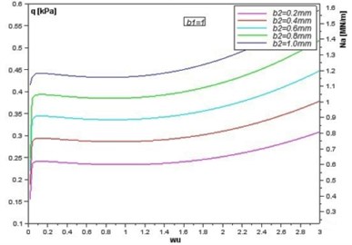
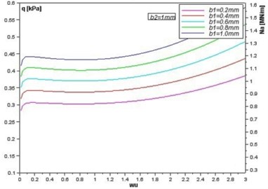
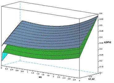
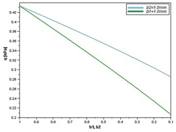
The curves in Fig. 4 represent the influence of changes in thickness of the specified face-layer upon the critical loads . The changes in the value of the longitudinal forces as well as the lateral pressure have the same nature so they can be shown on the same graph. As it could be expected, reducing the thicknesess of the faces results in a decrease in the critical loads. However, a difference can be noted with respect to the reduction of the thickness of the top (Fig. 4(b)) and bottom (Fig. 4(a)) layer. The changes of the critical loads are greater when the thickness of the bottom layer is changed. These differences can be seen in Fig. 5(a). The surface in blue color represents a constant thickness of the bottom layer (1 mm) and the top layer of different thickness. The surface in green color represents a constant thickness of the top layer (1 mm) and the bottom layer of different thickness. The described difference is clearly visible in Fig. 5(b), which shows the curves for the specific value of the parameter 1. It can be concluded that the thickness of the bottom layer is more important for the stability of the shell under consideration. The accurate determination of the causes of this difference is ambiguous. This may result from the method of load of the analyzed shell. Further research is needed in this area.
Fig. 4Equilibrium paths for various thicknesses of the face layers: a) constant value of b1 and variable value of b2; b) constant value of b2 and variable value of b1
a)
b)
Fig. 5Lateral pressure q as a function of deflection (wu) and changes in thickness b1,b2: a) in the whole range of parameter wu, b) for wu= 1
a)
b)
7. Conclusions
The objective of this paper is to derive a theoretical solution to the elastic-plastic stability problem of a sandwich conical shell. For the shell with the parameters accepted in the analysis, the stability loss process occurs in the elastic-plastic state of stress. The work presents the influence of the thicknesses of face layers on the equilibrium paths, as well as on the values of the critical loads. The presented here method is based on analytical-numerical approach. Selecting an appropriate thickness of the load carying faces could be important because if the critical load increases, the buckling resistance of the shell becomes higher. The method presented here is a general one and can be used in design sandwich shell structures.
References
-
Zielnica J. Stability of Elastic-Plastic Shells. Poznan Uni. of Tech., WPP, 2001, (in Polish).
-
Magnucki K., Ostwald M. Stability and Optimization of Sandwich Structures. Red. of collective work, Poznan Uni. of Tech + Uni. of Zielona Gora, 2001, (in Polish).
-
Błachut J. Elastic stability of imperfect stiffened conical shells cantilevered cylinders. Journal of Theoretical and Applied Mechanics, No. 46, Issue 4, 2008, p. 741-761.
-
Błachut J. On elastic–plastic buckling of cones. Thin-Walled Structures, No. 49, 2011, p. 45-52.
-
Błachut J., Ifayefunmi O. Plastic buckling of conical shells. Journal of Offshore Mechanics and Arctic Engineering, Vol. 132, 2010, p. 1-11.
-
Damatty A. A., Attar M., Korol R. M. Inelastic stability of conical tanks. Thin-Walled Structures, No. 31, 1998, p. 343-359.
-
Golzan B. S., Showkati H. Buckling of thin-walled conical shells under uniform external pressure. Thin-Walled Structures, No. 46, 2008, p. 516-529.
-
Jabareen M., Sheinma I. Stability of imperfect stiffened conical shells. International Journal of Solids and Structures, No. 46, 2008, p. 2111-2125.
-
Shen J., Lu G., Wang Z., Zhao L. Experiments on curved sandwich panels under blast loading. International Journal of Impact Engineering, No. 37, 2010, p. 960-970.
-
Sofiyev A. H., Aksogan O. Buckling of a conical thin shell with variable thickness under a dynamic loading. Journal of Sound and Vibration, No. 270, 2004, p. 903-915.
-
Spagnoli A. Different buckling modes in axially stiffened conical shells. Engineering Structures, No. 23, 2001, p. 957-965.
-
Paczos P., Zielnica J. Critical load of a bilayered orthotropic elastic–plastic conical shell with the change of the shell basic surface location. Thin-Walled Structures, No. 45, 2007, p. 911-915.
-
Paczos P., Zielnica J. Stability of orthotropic elastic–plastic open conical shells. Thin-Walled Structures, No. 46, 2008, p. 530-540.
-
Jaskula L., Zielnica J. Large displacement stability analysis of elastic–plastic unsymmetrical sandwich cylindrical shells. Thin-Walled Structures, Vol. 49, Issue 5, 2011, p. 611-617.
-
Zielnica J. Inelastic buckling of a layered conical shell. Proceedings of the 2nd Intern. Conf. on Thin-Walled Structures, ICTWS, Ed. Elsevier, Singapore, 1998, p. 247-255.
-
Zielnica J. Non-linear stability of elastic–plastic conical shell under combined load. Journal Theor. Appl. Mech., No. 41, Issue 3, 2003, p. 693-709.
-
Tertel E., Cyganiuk J., Kuryło P. Buckling of elastic-plastic sandwich conical shells – theoretical studies. International Journal of Applied Mechanics and Engineering, Vol. 16, No. 1, 2011, p. 129-140.
-
Vinson J. R. Sandwich Structures. Appl. Mech. Rev., Vol. 54, No. 3, 2001, p. 201-214.
About this article

