Abstract
The performance of high-speed motorized spindle system is greatly affected by spindle’s thermal and dynamic behavior. So, it is very important to predict these properties in design stage of spindle system. However, the thermal and dynamic behaviour reacts upon each other for the high rotational speed and complex structure of the spindle system. To control and optimize the dynamic behaviour and the temperature rise of spindle, this paper developed a dynamic and thermal coupled model of the spindle system by using the finite element method (FEM). The shaft and rotor were modeled as Timoshenko’s beam, the rational interference fit between shaft and rotor was treated as mass-spring combinations, the bearings were modeled as nonlinear spring element. The thermal analysis procedure contained the calculation of heat generation and confirmation of boundary condition. The accuracy of this coupled model was validated by corresponding experiments. With this coupled model, the thermal and dynamic performance of the spindle system was studied. The effects of rotational speed, axial preload and material of bearing and the diameter of shaft on thermal and dynamic behavior were analyzed. The spindle system was optimized with the result of analyses above. After optimization, the temperature rise of spindle system falls significantly to 24.5°C, which was 30.2°C before, while the dynamic stiffness at working speed increases from 156 to 197 N/μm.
1. Introduction
High-speed motorized spindle is one of the most important components of high-speed grinding machines that directly connects grinding wheel and plays a critical role in grinding machining accuracy and reliability. To improve the performance of the spindle, it is necessary to optimize the spindle’s structure to get better dynamic and thermal properties. A lot of researches on the dynamic behaviour have been carried out [1-3]. Ruhl [4] was one of the earliest researchers who use the finite element method (FEM) to model rotor systems for predicting the dynamic performance of the spindle system. Yusuf Altintas [5] and Shuyun Jiang [6] outlined general dynamic models, which consist of spindle shaft, angular contact ball bearings and housing. These models have been experimentally verified. The thermal performance is another main research focus of the spindle system and has been studied by many researchers [7-8]. While current study about the dependence of structure both on dynamic and thermal properties is rarely reported. Considering the fact that these two properties interacts each other closely, it is important to investigate both dynamic and thermal performance in the design and optimization stage of the spindle system.
To address this issue, this paper developed a dynamic and thermal coupled model for the spindle system. Furthermore, by using the finite element method, the thermal and dynamic performances of the spindle were studied. The effects of rotational speed, axial preload and material of bearing and the diameter of shaft on thermal and dynamic behavior were analyzed. The spindle system was optimized through the result of analyses above. After optimization, the temperature rise of spindle system falls significantly to 24.5 ºC, which was 30.2 ºC before, while the stiffness at working speed increases from 156 to 197 N/μm.
2. Model of high-speed spindle system
2.1. Thermodynamic coupled model of spindle system
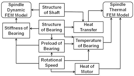
The high-speed motorized spindle contains several mechanically and thermally interactive phenomena with closed-loop and nonlinear natures. Fig. 1 shows the physical models that express the dynamic and thermal performance of the spindle system, as well as major independent variables. The independent variables are divided into structure variables and operation variables. The structure variables include the structure of shaft and bearings; the operation variables contain preload of bearing and the rotational speed.
Fig. 1Coupled model of spindle system
2.2. Structure of high-speed spindle system
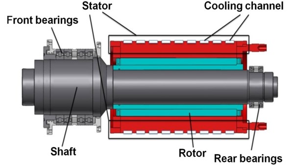
The high-speed spindle system with a maximum rotating speed of 10000 rpm experimentally, is shown as Fig. 2. The spindle system is mainly composed of shaft, stator, rotor, bearings and other major component parts with rated power 41.5 kW. The material of the shaft is 42 CrMo; bearing steel, silicon sheet and 45 steel are respectively used for bearings, rotor and other parts. The shaft is supported by the preloaded bearings, i.e. two pairs of parallel front bearings and one pair of parallel rear bearings. Here, the type of front bearings is HCB71924-E-P4S and the rear bearings’ type is HCB71913-E-T-P4S. The preload of the front bearings is 212 N, while 55 N for the rear bearings. The structure outside the bearings is the foundation which includes the bearing housing.
Fig. 2High-speed spindle system
2.3. Equations of motion for the spindle system
The length of the shaft is 715 mm, maximum diameter of shaft is 120 mm. The length and diameter of the rotor is 350 mm and 126 mm. Due to the size of the shaft, shear deformations is taken into account to increase the precision of FEM (finite element model). The Timoshenko beam theory which includes the shear deformation and rotational inertia effect is used to model the shaft and rotor, making it suitable for describing the behavior of spindle system. Dynamic equations were obtained by using Lagrange formulation associated with a numerical finite element method. A special three dimensional (3D) rotor-beam element with two nodes and five degrees of freedom per element was developed. The motion of each FE node is described by three translational and two rotational degrees of freedom.
Considering centrifugal and gyroscopic effects, the equations of motion of the shaft and rotor can be expressed in matrix forms by using Lagrange’s equations:
where and are the stiffness and mass matrices of shaft and rotor elements, is the skew-symmetric gyroscopic matrix of the rotational shaft and rotor, is the mass matrix for the centrifugal force effect on the shaft and rotor, is the rotational speed, and are the external exciting force vector and constant radial force vector such as gravity force.
The rotor is heated-resistant up to 150 ºC and then fitted onto the shaft by shrink-fitting method. Vibration characteristics of the rotor and shaft are evaluated from the solution of eigenvalue problem expressed by the following equation:
where is stiffness matrix of shaft, is stiffness matrix of rotor. They can be obtained from the Timoshenko beam theory. is the connection stiffness between shaft and rotor. The connections between the rotor and shaft are treated as mass-spring combinations (shown in Fig. 3). The stiffness matrix and can be expressed as:
In this study are not considered because they have little effect on dynamic performance and are not the error sensitive degrees of spindle system. When calculating the stiffness of the connections between the rotor and shaft. The shaft is assumed rigid and smooth, the rotor is assumed elastic and rough. The height of rotor obeys a Gaussian distribution. From the research [9], the stiffness can be expressed as:
where is the number of contact apexes whose shape are assumed as balls, E is the modulus of elasticity of rotor, is the variance of Gaussian distribution of height of rotor, is the curvature of apexes, is the assembly pretightening force of rotor. is the distance between rotor and shaft.
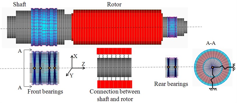
The FE model of spindle system is shown in Figure 3. In order to increase the calculating speed, the FE model is simplified: the small holes, small shaft shoulders and angle of chamfers are neglected in this model. The shaft and rotor are meshed by using Timoshenko beam element. The shaft is supported by six ball angular contact bearings which plays an important role in the dynamic performance of high-speed spindle system. The mesh type of bearings is hexahedron. In order to get good accuracy, the number of mesh elements of each bearing is more than 200. The spider node (orange point) which rigidly connects every node of inner rings represents the inner ring of bearing. The outer ring of bearing is fixed in the housing and assumed to be completely restraint (shown in A-A in Figure 3). The balls of bearing are treated as springs in , and direction.
Fig. 3Dynamic FE model of spindle system
When the high-speed spindle system operating at high speed, equation of deformation of the bearing under the load from the rotor can be expressed as:
where and are the forces and moments loaded on bearing in their corresponding directions. and are the linear and angular displacements of bearing in their corresponding directions. is the stiffness of bearing in direction when the load on bearing is in direction. According to the Hertz elastic theory, the relationship between force and deformation is nonlinear; therefore the stiffness in any direction is not constant. The stiffness in one direction in one balance position could be obtained by differentiating load (moment) in its corresponding deformation. For example, the stiffness in direction can be expressed as:
In this study, the stiffness in , and are considered. The stiffness in and are not considered, because they have little effect on the dynamic stiffness of spindle system and will greatly slow down the calculation speed.
By assembling equations of rotor, shaft and bearing, the following general nonlinear dynamic equations of the high-speed spindle system can be obtained:
where is the structural damping which should be obtained from experimental modal analysis.
2.4. Theoretical analysis of heat generation and transmition
The heat in bearing is result from the friction between balls and the ring race, the friction between bearing, lubricant and seal.
The heat source of the bearings can be expressed as:
where is friction torque, is speed. Friction torque is the sum of velocity torque and load torque :
According to Palmgren proposed algorithm, reflects the hydrodynamic lubricant loss, and reflects the loss of partial poor dynamic friction and the elastic hysteresis loss.
When 2000 cSt∙r/min, could be expressed as:
where is the middle diameter of bearing, is empirical constant, is kinematic viscosity. can be calculated from:
where is a coefficient which is determined by the type and load of bearing [10-11]. For the double row angular contact ball bearing . is the equivalent static load of bearing, is the rate static load of bearing. For the parallel angular contact () ball bearing . is the load on bearing in radial direction, is the load on the bearing in axial direction. is the load calculation which determines friction torque of the bearings.
In this case spindle bearings are lubricated with oil and gas, the convection can be fitted with a polynomial formula [8]:
where is air flow rate, is the outer diameter of bearings, is the inner diameter of bearing.
The finite element model of the spindle system mainly includes shaft, front bearings, rear bearings, stator and rotor. Neglect the details of the spindle system to simplify the model. Then use Femap software to do the pre-treatment. Load the heat generation, force and boundary conditions gotten from the above formulas. The ambient temperature is given as 20 ºC, the load on the front part where fixed the grinding wheel is 100 N. The parameters of the high-speed motorized spindle are listed in Table 1.
Table 1Parameters of spindle system
Parameters | Value and type |
Length of the spindle | 715 mm |
Type of front bearing | HCB71924 |
Diameter of front bearings’ ball | 8.25 mm |
Axial preload of front bearing | 212 N |
Diameter of shaft in front bearing | 100 mm |
Type of rear bearing | HCB71913 |
Axial preload of rear bearing | 55 N |
Maximum rotational speed | 10000 rpm |
3. Results and discussion
3.1. Dynamic and thermal analysis and verification
The result of modal analysis of spindle system is shown in Table 2. The first four modal frequencies are 255, 390, 700 and 850 Hz respectively.
Table 2Modal frequencies of spindle system
1st | 2nd | 3rd | 4th |
250 Hz | 400 Hz | 720 Hz | 860 Hz |
The modal frequencies can reflect the resonant frequencies. While this analysis result cannot show the dynamic performance of the high-speed spindle system in working speed range, especially for the frequently-used working speed that are not covered in the resonant frequency range. The dynamic stiffness which can display the deformation under the external force in working speed range is used to evaluate the dynamic property of spindle system in this study.
The dynamic stiffness can be expressed as the reciprocal of the frequency response function (FRF):
where is the FRF from grinding wheel to front shaft node, is the force loaded on the grinding, is the deformation of font shaft node.
The result of static stiffness analysis is shown in Fig. 4(a). It indicates that the deformation of the front shaft node is mounted is 0.602 μm. It can be obtained that the static stiffness of the spindle system is 163 N/μm.
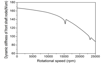
The dynamic stiffness of spindle system (shown in Fig. 4(b)) displays that the dynamic stiffness of the spindle system decreases with the increase of rotational speed. Because as the rotation speed increases, the gyroscopic moment and centrifugal force will increase, in turn, the dynamic stiffness of the rolling bearing is softened, and consequently, the dynamic stiffness of the spindle is decreased. When the spindle rotates at the maximum rotating speed (10000 rpm), the dynamic stiffness is 156 N/μm which is 95 % of the static stiffness.
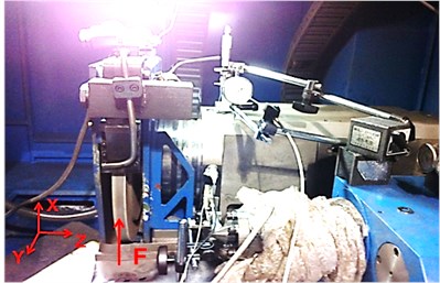
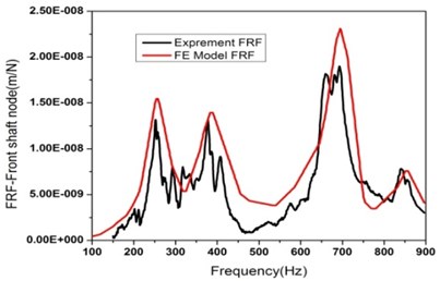
The dynamic stiffness is difficult to measure because the force loaded on the grinding wheel cannot be accurately measured. The FRF which is the reciprocal of dynamic stiffness is measured to verify the accuracy of the model (shown in Figure 5(a)). The displacement of the front shaft node was recorded using displacement transducers (accuracy of 1 um, displacement range of 0-0.5 mm). The impact hammer is hammered on the grinding wheel in direction. The signals from displacement transducers and the hammer are collected by LMS whose measurement frequency range is set from 0 to 1080 Hz. The front shaft node FRF in direction from the FE model and experiment are show in Fig. 5(b). The first four modal frequencies gotten from experiment are 255, 390, 700 and 850 Hz. These frequencies and FRF curve are in consistent with the analysis result of FE model.
Fig. 4Stiffness of spindle system: a) static stffness and b) dynamic stiffness as rotational speed rises
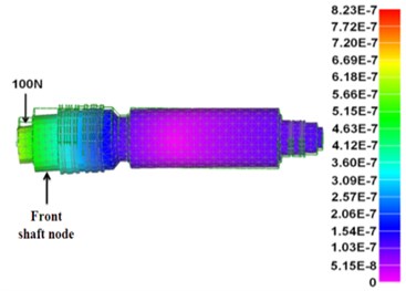
a)
b)
Fig. 5FRF of front shaft node: a) FRF experiment set up and b) FRF from experiment and FE model
a)
b)
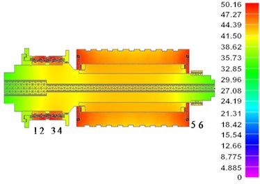
The simulation result of steady-state thermal analysis of the spindle system when its rotational speed is 10000 rpm is shown in Fig. 6(a). The maximum temperature rise of rotor is 30 ºC. It is acceptable for the rotor. The maximum temperature rise occurs at the front bearings is 30.2 ºC. According to the engineering experience, the safe temperature rise of the bearing is 25 ºC. So the temperature rise of the front bearings is forbidden for high-speed spindle operation and should be cooled down.
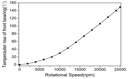
Fig. 6(b) shows the effect of the rotational speed on the temperature rise of the front bearings. The temperature rise goes up quickly with the rotational speed increases. So the rotational speed worsens both the dynamic and thermal performance of the spindle system.
The temperature rises of the bearings are measured by platinum resistance sensors which are set up on the out race rings of bearings to verify the accuracy of the FE model (shown in Fig. 7). The signals from platinum resistance sensors are collected by NI data acquisition card. The rotational speed of spindle system is 10000 rpm. The bearings are numbered 1, 2, …, 6 from left to right which is shown in Figure 6(a). The temperature rises of bearings from experiment and FE model are listed in Table 3. The result from experiment is a little lower than the measured ones. Because some heat of the bearings transmit to the housing of bearing which is not considered in the FE model. The maximum error of the model is 7 %. So the FE model is accurate enough to predict the thermal and mechanical behavior of high-speed spindle system.
Fig. 6Temperature rise of spindle system: a) temperperature at maximum rotating speed and b) temperperature rise as rotational speed rises
a)
b)
Fig. 7Temperature measurement of spindle system
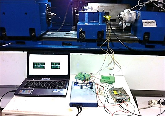
Table 3Temperature rises of bearings from experiment and FE model
Number | 1 | 2 | 3 | 4 | 5 | 6 |
Experiment (°C) | 26.5 | 27.1 | 28.5 | 27.4 | 18.1 | 18.2 |
FE model (°C) | 25.3 | 29.1 | 30.2 | 28.4 | 19.4 | 18.5 |
3.2. Comparison and discussion
Analyze the effect of the structure variables and operation variables on the dynamic and thermal performance of the spindle system. The structure variables include the structure of shaft and bearings; the operation variables contain preload of bearing. The rotational speed is the maximum rotating speed of spindle system (10000 rpm).
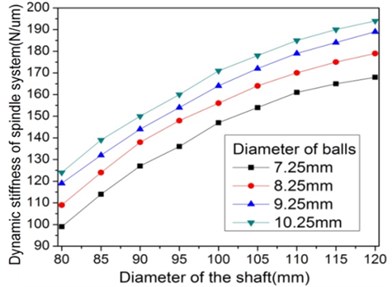
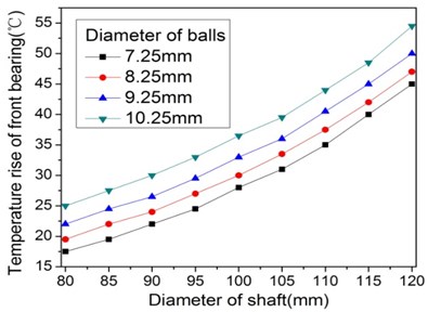
The effect of the diameters of the shaft in front bearing and balls of the bearing on the stiffness and temperature rise of the spindle system is shown in Fig. 8. It indicates that the dynamic stiffness of spindle system increases quickly when the diameter of shaft is smaller than 100 mm and slowly when the diameter of shaft is larger than 100 mm. For the same diameter of the shaft, the dynamic stiffness of spindle system raised as the diameter of balls increases, while the growth becomes more and more small. The temperature rise of the front bearing increases slowly when the diameter of shaft is smaller than 100 mm and quickly when the diameter of shaft is larger than 100 mm. For the same diameter of the shaft, the temperature rise of the front bearing rises up as the diameter of balls increases and the growth becomes more and more large. It is opposite to the effect of diameter of balls on the dynamic stiffness of spindle system.
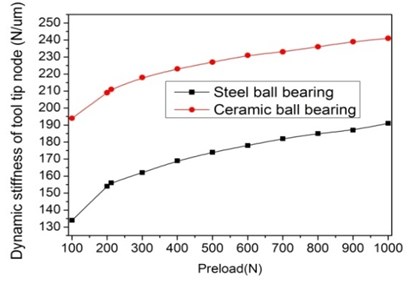
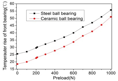
For the maximum rotating speed of the spindle, the effect of the preload and material of the front bearing on the dynamic stiffness and temperature rise of the spindle system is shown in Fig. 9. The ceramic ball bearing has better performance both in the dynamic and thermal properties of the spindle system than the steel ball bearing. It is because the ceramic ball has larger Young modulus and smaller coefficient of expansion. The stiffness of the spindle system with the steel and ceramic ball bearing both increase quickly within the preload of 300 N and rises slowly without 300 N. The temperature rise of the front bearings goes up as the preload increases both for the steel bearing and ceramic ball bearing. The difference of the temperature rises between the steel and ceramic ball bearing decreases as the preload increases. Because as the preload increase, the lubrication film thickness is beginning to be invariant and causes the friction loss of bearing tends to be constant.
Fig. 8Effect of the diameter of shaft and bearings’ ball on dynamic and thermal performance of spindle system
a)
b)
Fig. 9Effect of the preload and metrical of front bearing on dynamic and thermal performance of spindle system
a)
b)
3.3. Optimization
Based on the result of analysis of the dynamic and thermal behavior of spindle system above, the first order optimization method is used to optimize the spindle system in this study. The displacement of front shaft node is set as . The maximum temperature of bearings is set as . The maximum dynamic stiffness of spindle means the minimum displacement under a certain load (100 N). , , are design variables (represent the diameter of shaft, diameter of balls of bearing, and preload of bearing, respectively). is the state variable, is the objective function.
With penalty function, the constraint condition is converted to no constraint equation, deriving the objective function and weighting function of state variable. The optimal solution is obtained after several iterations in the scopes of variables. is the material of bearing, and changes from steel to ceramic after using the first order method as the last step optimization. The procedure of optimization is shown in Table 4.
For the solution 5 (the diameter of shaft is 90 mm, diameter of balls of bearing is 9.25 mm, preload of bearing is 300 N and material of bearing is ceramic), the high-speed spindle system obtains the optimal solution both in thermal and dynamic performance.
The analysis result of optimal structure selection of the spindle has been carried out (shown in Table 5). It can observed that the dynamic stiffness of the spindle system at the max rotational speed increases from 156 N/μm to 197 N/μm and the first model frequency rases by 7.2 %. The temperature rise of the front bearings has been reduced significantly to 24°C, which was 46.2°C before optimization. The thermal and the dynamic stiffness performance of the spindle are both improved.
Table 4Procedure of optimization
Iterations | (mm) | (mm) | (N) | (°C) | (um) | |
1 | 100 | 8.25 | 212 | Steel | 30.2 | 0.641 |
2 | 95 | 8.75 | 250 | Steel | 28.7 | 0.602 |
3 | 92 | 9.25 | 275 | Steel | 27.8 | 0.600 |
4 | 90 | 9.25 | 300 | Steel | 27.2 | 0.595 |
*5* | 90 | 9.25 | 300 | Ceramic | 24.5 | 0.510 |
Table 5Contrast of performance of the original and optimal structure
Dynamic stiffness (N/μm) | Temperature rise (°C) | First modal frequency (Hz) | |
Original | 156 | 30.2 | 250 |
Optimal | 197 | 24.5 | 268 |
Improved by | 26.2 % | 18.9 % | 7.2 % |
4. Conclusions
A thermodynamics coupled model of high-speed motorized spindle system has been presented by using the finite element method. The accuracy of this coupled model was validated by corresponding experiments. With this model, the dynamic and thermal performances of the spindle system were studied. The effect of parameters of the spindle system on the dynamic and thermal behavior was analyzed. The following conclusions can be obtained.
The rotational speed worsens both the dynamic and thermal performance of the spindle system and the effect gets more and more serious as the rotational speed increases.
The ceramics ball bearing has better performance than the steel ball bearing both in the dynamic and thermal properties of spindle system. The two properties of spindle system both become worse as the preload of the bearing increases.
The rise of the diameters of bearings’ balls and shaft in the front bearing improves the dynamic performance, while worsens the thermal property of bearings.
After optimization, the temperature rise of spindle system falls significantly to 24°C, which was 30.2°C before, while the dynamic stiffness increases from 156 to 197 N/μm, the first model frequency rases by 7.2 %.
References
-
S. Y. Jiang, S. F. Zheng A modeling approach for analysis and improvement of spindle-drawbar-bearing assembly dynamics. International Journal of Machine Tools & Manufacture, Vol. 50, 2010, p. 131-142.
-
C. H. Chen, K. W. Wang, Y. C. Shin An integrated approach toward the dynamic analysis of high-speed spindles. Part I: System model; Part II: Dynamics under moving end load. International Journal of Vibration and Acoustics, Vol. 116, 1994, p. 506-522.
-
Opitz H., Gunther D., Kalkert W. Kunkel The study of the deflection of rolling bearing for machine tool spindles. Proceeding of the 6th MTDR Conference, Vol. 34, 1965, p. 257-269.
-
R. L. Ruhl, J. F. Booker A finite element model for distributed parameter turbo rotor systems. ASME Journal of Engineering for Industry, 1972, p. 128-139.
-
Yuzhong Cao, Yusuf Altintas A general method for the modeling of spindle-bearing systems. Journal of Mechanical Design, November 2004, p. 126-134.
-
Shuyun Jiang, Shufei Zheng A modeling approach for analysis and improvement of spindle-drawbar-bearing assembly dynamics. International Journal of Machine Tools & Manufacture, Vol. 50, 2010, p. 131-142.
-
Z. Haitao, Y. Jianguo, S. Jinhua Simulation of thermal behavior of a CNC machine tool spindle. International Journal of Machine Tools and Manufacture, Vol. 47, 2007, p. 1003-1010.
-
Bernd Bossmanns, Jay F. Tu A thermal model for high speed motorized spindles. International Journal of Machine Tools & Manufacture, Vol. 39, 1999, p. 1345-1366.
-
Zheng Y., Rong Y., Hou Z. A finite element analysis for stiffness of fixture units. Journal of Manufacturing Science and Engineering, Vol. 127, 2005, p. 429-432.
-
B. R. Jorgensen, Y. C. Shin Dynamics of machine tool spindle/bearing systems under thermal growth. Trans. ASME, J. Tribol., Vol. 119, Issue 4, October 1997, p. 875-882.
-
Changlong Zhao, Xuesong Guan Thermal analysis and experimental study on the spindle of the high-speed machining center. AASRI Procedia, Vol. 1, 2012, p. 207-212.
About this article

This project is supported by National Major Projects (2009ZX4001-101), the National Basic Research Program of China (973 Program, 2009CB724400), Shanghai Leading Academic Discipline Project (Project Number B602), Innovation Fund of Ph. D. of Donghua University (BC201133) and Shanghai Scientific Research Programs (11JC1413202).
