Abstract
In past studies, the elastic effects of a workpiece were usually ignored or a workpiece was just expressed with Euler-Bernoulli beam theory in turning process, which made the stability of cutting process less accurate. This paper considers the deformation of the workpiece expressed with a more accurate Timoshenko beam model in analysis for chatter of cutting process. The cutting stability of the turning process is analyzed by combining both the elastic effects of the tool and the workpiece with regenerative chatter mechanisms and compared with the stability analysis results that the deflection of workpiece is ignored. Besides, the influences of workpiece length, radius, the cutting tool damping and stiffness on the analytical model are also studied. At last, the present model is compared with those obtained from Euler-Bernoulli theory. It is found that the critical chip width when we consider workpiece as a Timoshenko beam is greater than the other two cases.
1. Introduction
Machine tool chatter is a self-excited vibration problem occurring in large rates of material removal, resulting from the unavoidable flexibility between the cutting tool and workpiece [1]. When chatter occurs, it causes poor surface finishing, premature damage and breakage of cutting tools, as well as mechanical system deterioration. In general, chatter is a very important limiting factor which needs to be avoided in designing a manufacturing process. In order to obtain chatter-free machining process, people can only choose conservative cutting conditions which result in lower material removal rate. Therefore, it’s necessary to predict the stability limit to enhance material removal rate while maintaining product quality.
In past studies, the elastic effect of workpiece was usually ignored, and only the tool vibration was considered. However, cutting can also produce force on the workpiece which causes its deflection, and then the chip thickness gets changed. Therefore, the deflection of workpiece is equally important as the tool vibration. In view of its importance, some scholars did related research on the deflection of workpiece. Carrino et al. [2] deduced the dimensional deviations caused by workpiece deflections, vibrations of tool as well as material spring back. Luciano et al. [3] and L. Vela-Martínez et al. [4] established a multiple degrees of freedom model based on the compliance between the cutting tool and the workpiece to predict chatter in turning. M. Eynian et al. [5] considered the tool wear and process damping between the cutting tool and the workpiece. Dornfeld D. A. et al. [6] represented several features of the interaction between tool and workpiece related to instant depth of cut distribution. Based on variable stiffness in boring bars, Wang et al. [7] proposed a new method to suppress chatter, that is, continuously varying the natural frequency of the over a range to avoid self-excited vibration. Chen and Tsao presented two dynamic models of cutting tool with [8] and without [9] tailstock-supported workpiece based on beam theory. Sekar et al. [10] proposed a compliant two degrees of freedom dynamic cutting force model by considering the relative motion of workpiece with cutting tool, and they considered tool and workpiece as two separate single degree of freedom spring-mass-damper systems.
While some recent results of the vibration of the cutting tool are used to control and to improve the cutting surface. According to Zahia Hessainia et al. [11], one of the most important aims of experiments related to manufacturing was to achieve the desired surface roughness with the optimal cutting tool vibration. The goal was to minimize surface roughness, the exploitation of the response surface methodology optimization seemed to be a helpful technique. Antic A. et al. [12] thought tool wear was correlated to surface quality of the workpiece. The cutting parameters were altered to improve the surface quality while monitoring spindle vibration to show that process control of the process was possible.
Though someone considered the deflection of workpiece, they just regarded the workpiece as an Euler-Bernoulli beam which neglected the transverse shear as well as the rotary inertia. Although it is simple and can provide reasonable engineering approximations in many cases, it tends to slightly overestimate the natural frequencies. This problem is exacerbated for the natural frequencies of the higher modes. Besides, the prediction is better for slender beams than non-slender beams. However, Timoshenko beam can solve this problem. To do more accurate estimation, this paper is based on the theory of Chen C. K. et al. [9] and analyses the deflection of workpiece with the help of Timoshenko beam theory, and then goes on with stability analysis. Finally, we compare them with the results which ignore the elastic effects of workpiece.
2. Dynamic cutting model
2.1. Determine the deflection of the workpiece with Timoshenko beam theory
Timoshenko (1921, 1922) [13, 14] proposed the Timoshenko beam theory which considered the effect of shear as well as the effect of rotation relative to the Euler-Bernoulli beam. It is a great improvement for non-slender beams and for high-frequency responses where shear or rotary effects can play an important role and can’t be neglected. Besides, several authors have obtained the frequency equations and the mode shapes corresponding to various boundary conditions based on Timoshenko beam theory [15-18].
Now, workpiece is considered as a cantilever beam which is shown in Fig. 1. When there is a force performed at the free end of the workpiece, it will generate deflection. Next, we can obtain the deflection mainly with the knowledge of the literature [19].
Fig. 1Deflection of workpiece which is considered as a Timoshenko beam
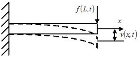
Through the combination of Lagrangian and Hamilton principle, we can get the equations of motion:
as well as the boundary conditions:
where is the density of the beam, the cross-sectional area, the area moment of inertia of the cross-section about the neutral axis, the axial location, the time, the transverse deflection at the axial location and time , the angle of rotation of the cross-section due to the bending moment at the axial location x and time , the shape factor, the shear modulus, the non-conservative transverse force per unit length.
As the forms of and are identical, we assume that they share the same time solution . Then the solution can be writen as the combination of time solution and spatial solution through separation of variable:
Substituting (3) into (1) without the term , we can get:
As and also have the same form, we can write them as following forms which only differ by a constant:
where is the constant coefficient, a vector of constant numbers and the wave number. Substituting (6) into (5) yields:
To have a non-trivial solution, the determinant of the above matrix has to be zero:
Then we get the form of eigenvalues:
When the frequency is less than , the spatial solution is written in terms of both sinusoidal and hyperbolic terms:
where:
Besides, and have the following relationships:
where is a constant given by:
stands for Poisson’s ratio.
Next, we can apply a set of boundary conditions to obtain the four unknown coefficients in the spatial solution. For cantilever beam, boundary conditions are as follows:
They can also be written in terms of spatial solutions, that is:
Substituting (14) into (11), we can get the frequency equations as well as the spatial solution which only including one unknown:
where is a constant. The corresponding spatial solutions are also referred to as eigenfunctions or mode shapes.
Next we seek the orthogonality conditions through which to obtain the free or forced response of the beam. For Timoshenko beam, the spatial Eq. (5) can be written using the operator formalism:
where stands for the nth vector of eigenfunctions and:
Now, we can verify the operators and are self-adjoint [20], namely:
First, Eq. (20) is automatically satisfied. Substituting (18) into (19) and integrating twice by parts, we obtain:
Note that the boundary conditions obtained from the variational problem (2) satisfy this condition, which proves that Eq. (19) is also satisfied. Then we can determine the orthogonality conditions through the nature of self-adjoint. Using Eq. (17) we can write Eq. (19) as:
Since for , in order for Eq. (22) to be zero, the integral has to be zero, that’s:
The above equation is referred to as the orthogonality condition, and when , it can be written:
Combining Eq. (23) and (24), we get:
Using the method of eigenfunction expansion, the solution in Eq. (1) can be expanded in terms of eigenfunctions as:
where stands for . Then the Eq. (1) can be written:
Using Eq. (17), the above equation becomes:
Multiplying by and integrating from 0 to results in:
where:
The solution is:
where and can be obtained from the initial conditions. Then using Eq. (26), we can successfully get the forced response of the beam.
2.2. Modeling of the cutting system
Since the dynamic cutting operations are very complicated, the turning system which is investigated in this study was simplified to one-dimensional second-order orthogonal cutting model. When the deflection of the workpiece is neglected, the cutting system model is shown in Fig. 2, where the workpiece is unwrapped. However, now we consider it. First, the cutting governing equation is as follows:
Here, is tool vibration at time and the parameters , , and are the equivalent mass, damping, and stiffness of the cutting tool and tool holder, is the cutting angle and is cutting force, which is given by:
where is cutting coefficient, is chip width, is the instantaneous chip thickness. We don’t consider the previous deflection of workpiece for convenience, so can be written as:
Fig. 2Cutting model which neglects the deflection of workpiece
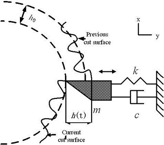
Here, represents nominal chip thickness and the term is the current offset of tool, is the offset of tool previous cycle, represents the period for successive passages of tool and represents the workpiece deflection. Because we only consider the end point cutting, the equivalence “” is assumed. As the natural frequency of the workpiece is much higher than the spindle speed, we just consider the first mode dynamics. Substituting (26), (33), (34) into (32) and making a Laplace transformation, we can get:
where:
The concentrated force can be written as:
Substituting (33), (34) into (29) and making a Laplace transformation, we can get:
where .
Combining (35) with (37), we can get:
where: , .
3. Stability analysis
Based on Eq. (38), we can get the characteristic equation:
Substituting , separating real and imaginary parts, the influences of natural frequencies have been included in the formula of the period for successive passages of tool and the depth of cut , and solving for and generates the following critical values:
where:
4. Results comparison and analysis
First, we consider a 0.5-m-long and 0.06-m-radius workpiece and compare the stability analysis results with the other model in which the elastic effects of workpiece are ignored. The corresponding parameters of tool and workpiece are as follows in Table 1.
In Eq. (40), represents the chip width which ignores the elastic effects of workpiece, and the size of reflects the size of the gap. Besides, the expression form of is identical for two cases. Therefore, spindle speed in revolution per second which is computed as is also the same. It can be seen that (41) has multiple solutions due to different values of . Thus, (40) and (41) define the stability limits of the system.
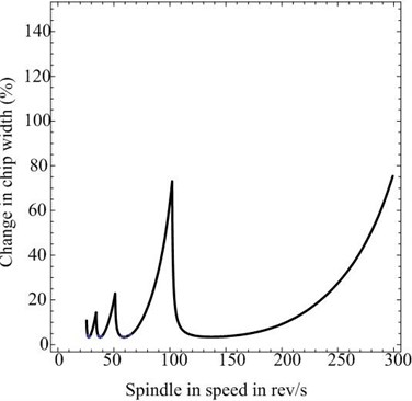
Fig. 3a) Comparison of the critical chip width between Timoshenko beam and that ignores the elastic effects of workpiece; b) the differential percentage of the critical chip width between Timoshenko beam and that ignores the elastic effects of workpiece
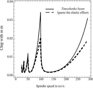
a)
b)
Fig. 3(a) shows the results of the critical chip width in which the solid line represents the situation where the elastic effects of workpiece are ignored and the dashed line represents the situation where we consider the workpiece as a Timoshenko beam. Fig. 3(b) shows the variation of percentage difference in chip width between them that is .
From the above comparison, we can see the critical chip width corresponding to two different cases are different. Besides, when we consider the deflection of workpiece, it becomes larger, and the smaller the value of , the larger the percentage of critical chip width difference.
Table 1The parameters of tool and workpiece [6, 14]
Parameters | Tool | Workpiece (steel) |
, Kg | 50 | – |
, kg/s | 2×10³, 4×10³, 6×10³ | – |
, N/m | 2×10⁷, 4×10⁷, 6×10⁷ | – |
, N/m2 | 2×10⁹ | – |
, deg | 70 | – |
, GPa | – | 180 |
, Kg/m3 | – | 7850 |
, m | – | 0.05, 0.25, 0.3, 0.5 |
– | 0.29 | |
– | 0.8855 | |
, m | – | 0.012, 0.06, 0.12, 0.14, 0.16 |
Next, we explore the influences of the length, radius, slenderness, damping and stiffness of the cutting tool on the proposed model.
4.1. Same radius for different lengths
In this case, we compare the difference in critical chip width between the case where the elastic effects of workpiece are ignored and a Timoshenko beam workpiece with a radius of 0.06 m for two different values in length as Figure 4. It shows the longer the length, the larger the percentage of critical chip width difference. Larger workpiece has smaller natural frequency but larger deflection and larger critical chip width.
4.2. Same length for different radius
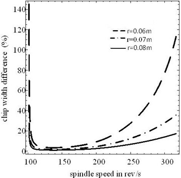
Figure 5 shows the percentage of critical chip width difference for three different workpieces of constant length 0.5 m with different radius. It can be seen that the percentage difference decreases progressively with the increase of radius. It can be explained that the smaller the radius, the larger the deflection, which results in larger critical chip width.
Fig. 4Differential percentage of critical chip width for same radius (0.06 m) and different length of workpiece
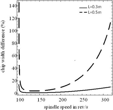
Fig. 5Differential percentage of critical chip width for same length (0.5 m) and different radius of workpiece
4.3. Same slenderness ratios for different dimensions
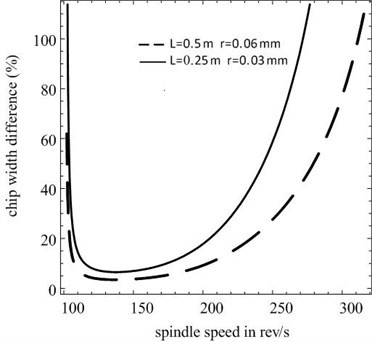
Figure 6 presents the results for two workpieces with the same slenderness ratio but different dimensions. One has a length of 0.5 m and a radius of 0.06 m, and the other has a length of 0.25 m and a radius of 0.03 m. As it is easy to cause larger deflections for the latter, it has larger percentage of critical chip width difference.
Fig. 6Differential percentage of critical chip width for the same slenderness ratio of steel workpiece
4.4. Effect of tool damping
Damping is a very important factor for stability analysis. Figure 7 shows the influence of damping on the critical chip width, and the workpiece has a length of 0.5 m and a radius of 0.06 m. In order to facilitate comparison, the spindle speed is selected as 200 rev/s. It can be seen that the larger the tool damping, the larger the critical chip width. Figure 8 presents percentage of critical chip width difference, and it also shows the larger the tool damping, the larger the percentage of critical chip width difference.
Fig. 7Effect of the cutting tool damping in the critical chip width
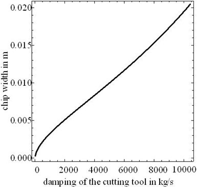
Fig. 8Differential percentage of critical chip width for different damping of tool
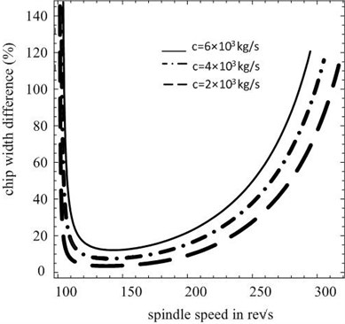
Fig. 9Effect of tool stiffness in the critical chip width
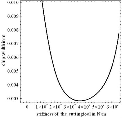
Fig. 10Differential percentage of critical chip width for different stiffness of cutting tool
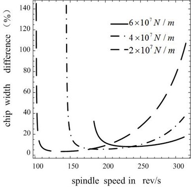
4.5. Effect of tool stiffness
Tool stiffness is also very important for stability analysis. Figure 9 shows the influence of tool stiffness on the critical chip width when workpiece still has a length of 0.5 m and a radius of 0.06 m. In order to facilitate comparison, the spindle speed is selected as 200 rev/s. Figure 9 shows a special case: the critical chip width decreases with the increase of tool stiffness in a certain range, and it is opposite in another range. The result demonstrates that it is necessary to select appropriate tool stiffness. Figure 10 presents the percentage of critical chip width difference, and it is different for different cutting stiffness.
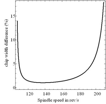
4.6. Comparisons between present model and Euler-Bernoulli beam
Just as discussed before, Euler-Bernoulli beam neglects the transverse shear and the rotary inertia which brings some errors. Through comparisons between present model and Euler-Bernoulli beam, we can find the superiority of the former. Figure 11 shows the percentage of critical chip width difference for one workpiece which has a length of 0.05 m and a radius of 0.006 m. Timoshenko beam has larger critical chip width than Euler-Bernoulli beam, and it can be seen that the maximum difference between the two critical chip widths is over 17 %.
Besides, The Timoshenko model is a major improvement especially for high-frequency responses where shear or rotary elects cannot be neglected. With the great increase of turning speed, Timoshenko model will have a greater advantage compared to Euler-Bernoulli beam model.
Fig. 11The differential percentage of the critical chip width between Timoshenko beam and Euler-Bernoulli beam
5. Conclusions
In this paper, a new analytical model considering both tool and workpiece dynamics is proposed to predict chatter in turning. The workpiece is modeled as a more realistic and accurate Timoshenko beam which adds the effect of shear as well as the effect of rotation to the Euler-Bernoulli beam. The forced response of the Timoshenko beam is derived by an eigenfunction expansion approach. Based on regenerative chatter mechanisms, the stability lobe diagram is obtained. Compared with the workpiece model without the deflection and the one by using Euler-Bernoulli model, the present model can obtain larger critical chip width and larger stability area. Furthermore, chip width deviation between the present model and the workpiece model neglecting the deflection is studied by varying some parameters, including the geometric dimensions of the workpiece, damping of the cutting tool. It is found that either decreasing the radius of workpiece or increasing damping of cutting tool can raise the deviation, when it is more necessary to apply the new model presented in this paper. In addition, the effects of damping and stiffness of the cutting tool on the dynamic stability of the proposed analytical model have been given. The results show that it can provide larger critical chip width by increasing damping of the tool. However, the stiffness has the opposite effect in a certain range and beyond the range it has the same effect as the cutting tool damping.
As the new model can obtain more accurate stability lobe diagram, it is significant to choose the reasonable parameters, for instance, the best spindle speed and chip width. Moreover, active control is also necessary to allow for a sufficiently broad range of stability, such as increasing the cutting tool damping and selecting appropriate cutting tool stiffness.
References
-
Turkes E., Orak S., Neseli S., Yaldiz S. Linear analysis of chatter vibration and stability for orthogonal cutting in turning. Int. J. Refract. Met. Hard Mater., Vol. 29, Issue 2, 2011, p. 163-169.
-
Carrino L., Giorleo G., Polini W., Prisco U. Dimensional errors in longitudinal turning based on the unified generalized mechanics of cutting approach. Part I: Three-dimensional theory. Int. J. Mach. Tools Manuf., Vol. 42, Issue 14, 2002, p. 1509-1515.
-
Vela-Martínez L., Jáuregui-Correa J. C., Rubio-Cerda E., et al. Analysis of compliance between the cutting tool and the workpiece on the stability of a turning process. Int. J. Mach. Tools Manuf., Vol. 48, Issue 9, 2008, p. 1054-1062.
-
Vela-Martínez L., Jáuregui-Correa J. C., Rubio-Cerda E., et al. Analysis of compliance between the cutting tool and the workpiece on the stability of a turning process. Int. J. Mach. Tools Manuf., Vol. 48, Issue 9, 2008, p. 1054-1062.
-
M. Eynian, Y. Altintas Chatter stability of general turning Operations with process damping. Journal of Manufacturing Science and Engineering, Vol. 131, Issue 4, 2009, p. 041005.
-
Dornfeld D. A., Oliveira J. F. G., Lee D., et al. Analysis of tool and workpiece interaction in diamond turning using graphical analysis of acoustic emission. CIRP Annals-Manufacturing Technology, Vol. 52, Issue 1, 2003, p. 479-482.
-
Wang M., Fei R. Y. Improvement of machining stability using a tunable-stiffness boring bar containing an electrorheological fluid. Smart Mater. Struct., Vol. 8, Issue 4, 1999, p. 511-514.
-
Chen C. K., Tsao Y. M. A stability analysis of turning a tailstock supported flexible work-piece. Int. J. Mach. Tools Manuf., Vol. 46, Issue 1, 2006, p. 18-25.
-
Chen C. K., Tsao Y. M. A stability analysis of regenerative chatter in turning process without using tailstock. Int. J. Adv. Manuf. Technol., Vol. 29, Issue 7-8, 2006, p. 648-654.
-
Sekar M., Srinivas J., Kotaiah K. R., Yang S. H. Stability analysis of turning process with tailstock-supported workpiece. Int. J. Adv. Manuf. Technol. Technology, Vol. 43, Issue 9-10, 2008, p. 862-871.
-
Timoshenko S. P. LXVI. On the correction for shear of the differential equation for transverse vibrations of prismatic bars. Philosophical Magazine Series 6, Vol. 41, Issue 245, 1921, p. 744-746.
-
Timoshenko S. P. On the transverse vibrations of bars of uniform cross-section. Philosophical Magazine Series 6, Vol. 43, Issue 253, 1922, p. 125-131.
-
Kruszewski E. T. Effects of Transverse Shear and Rotary Inertia on the Natural Frequencies of a Uniform Beam. National Advisory Committee for Aeronautics, 1949.
-
Zahia H., Nabil K., Ma Y., et al. Turning roughness model based on tool-nose displacements. Mechanics, Vol. 19, Issue 1, 2013, p. 112-119.
-
Antić A., Kozak D., Kosec B., et al. Influence of tool wear on the mechanism of chips segmentation and tool vibration. Tehnički Vjesnik, Vol. 20, Issue 1, 2013, p. 105-112.
-
R. W. Traill-Nash Arc The effects of shear flexibility and rotatory inertia on the bending vibrations of beams. Q. J. Mech. Appl. Math., Vol. 6, Issue 2, 1953, p. 186-222.
-
Dolph C. L. On the Timoshenko theory of transverse beam vibrations. Q. Appl. Math., Vol. 12, 1954.
-
Huang T. C. The effect of rotatory inertia and of shear deformation on the frequency and normal mode equations of uniform beams with simple end conditions. J. Appl. Mech., Vol. 28, Issue 4, 1961, p. 579-584.
-
Han S. M., Benaroya H., Wei T. Dynamics of transversely vibrating beams using four engineering theories. J. Sound. Vibr., Vol. 225, Issue 5, 1999, p. 935-988.
-
Meirovitch L. Analytical Methods in Vibrations. The Macmillan Company, New York, 1967.
About this article

This work is supported by National Science Foundation of China (No. 51175071), the Fundamental Research Funds for the Central Universities (No. N120203001), Major State Basic Research Development Program of China (No. 2011CB706504), Science Foundation of Liaoning Province (No. 201102072).
