Abstract
The work is devoted to the development and application of computational and experimental methods and means of increasing the efficiency of vibration diagnostics of power equipment, including gas compressor units of gas transmission systems. There are solutions of the problem of natural frequencies and modes of its vibrations to calculate of the levels of power ratio (sensitivity functions) of equipment units and they are summarized in the form of computational models.
1. Introduction
Power equipment application technology considers the problem of diagnosing incipient defects to be the most important, including diagnosing the technical condition of machines for the torsional vibrations. The use of torsional vibrations for recognition of the technical condition and consideration of torsional vibrations in assessing the residual life allows to take measures to increase the reliability of power equipment [1-3].
2. The practical need to improve vibration diagnostics
The analysis of power equipment units failure statistics shows that 80 % of the equipment units failure is caused by damage of the bearings due to imbalances, misalignment of shafts, shaft bending, bearing faults and other causes. Therefore, methods, means and standards based on monitoring and analyzing the flexural and longitudinal vibrations of shafts are widely used in the vibration diagnostics of power equipment (which are transmitted to the bearings) [4].
In practice, algorithm for vibration control in the general level of vibration of bearing housings or machine bodes has got a wide application (RMS amplitude of the vibration velocity) in the frequency range 10 ... 1000 (1500) Hz. The increase in the overall level of vibration 2.5 times (8 dB) compared to the limit value for the normal (good) state indicates the transition zone in the maximum allowable (pre-fault) state. An increase in the amplitude by 10 times (20 dB) in comparison with a reference spectrum in the transition zone is invalid (emergency) state and the necessity to repair. However, the algorithm does not allow to take into account a number of factors affecting the formation and development of degradation processes in machines, to identify defects that appear in the torsional vibrations of shaft lines of equipment (neither transmitted to the bearings, or having a low level of the signal in the vibrations of the support units in the context of high levels of interference) [4-7].
At present, the most dangerous part of the equipment failure occurs due to damage of the equipment main components carrying the load process (couplings, shafts, blades, and others) (according to the statistics up to 20 % of equipment nodes failure for mechanical parts), which results in an increase of equipment failures, reduction of the time between failures of machines and the danger of the emergence of system failures (Fig. 1).
However, the staff of the automatic control of power machines is not equipped with control and diagnostic hardware to determine the beginning of defects in these parts of machinery and their development trends. According to the analysis, a significant impact on the appearance and development of defects (cracks, damage of teeth gear couplings, fretting corrosion mates rotor-hub gear and others) in the details of machinery construction has the stress-strain state of the major components caused by torsional vibrations shafting (in transient dynamic conditions of the machines). Therefore, taking into account all parameters of machines condition monitoring in the creation of the improved model of all existing loads on shafting and structural elements of machines it is necessary to develop a means of monitoring and analysis of machines shafting torsional vibration. According to this model it is necessary to determine the stress-strain state of the details of the construction of machines, to perform the analysis and to identify dangerous areas, where there are possible defects. These areas of shafting machines need continuous monitoring of the stress-strain state of the metal, determination the time of occurrence of defects and the corresponding residual life, taking measures to prevent the destruction or failure [2, 5, 7-9].
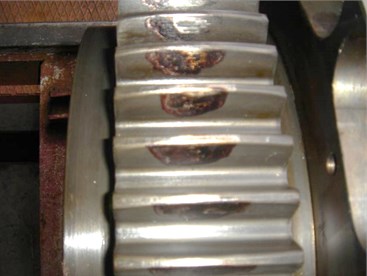
Fig. 1Failure and simple gas compressor units due to defects: a) EGCU-12500 (EGCU-235-23-3) with a centrifugal compressor C-235-21-1 without hydrodynamic coupling due to damage to the gear sleeve of shaft-gear multiplier (chipped tooth and damage to a number of other teeth); b) EGCU2-12.5/76-1.5 with a centrifugal compressor C-285-22-1 due to damage to the gear coupling (welding teeth of half-clutch gear /side of the drive/ and gear hub motor)
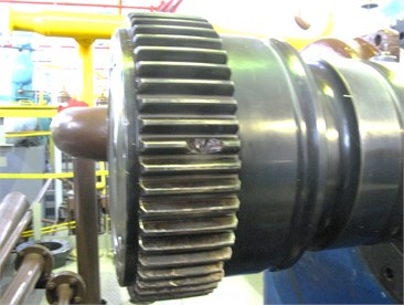
a)
b)
3. The theoretical justification of the proposed methods and means
A necessary preliminary step to improve the efficiency of vibration diagnostics of machines is justification for the selection and development of methods and means of measurement of torsional vibrations, evaluation of possible ways to diagnose. For this purpose there were used methods of mathematical modeling as cost-effective ones and computational and experimental methods and related software and hardware were developed (Fig. 2) [2, 5, 10]:
- method of test control of object vibration parameters on energy modes for the analysis of natural vibrations of the system;
- vibration diagnostics of machines based on the indicators of sensitivity to influences exciting details vibrations.
In contrast to existing methods of vibration diagnostics the proposed methods are based on a calculation of the energy spectra of the object of diagnosis (based on indicators of the sensitivity of the system elements to effects exciting vibrations), significantly facilitating the prediction of incipient defects on the structure of the product. Inertial characteristics are defined in the simplest cases by the lists of inertial elements reflecting the rotational motion of bodies rotations. Linear elastic forces by the elastic members are described. Elements and solids introduced in this way are composed of geometric (kinematic) and the physical parts. The first includes variables (coordinates) describing the generalized coordinates and moving of mechanical model objects, the second reflects the physical characteristics – inertial and elastic properties (determined by the computer program).
Fig. 2The block diagram of the system of vibration diagnostics (augmented by techniques to improve the efficiency of vibration diagnostics)
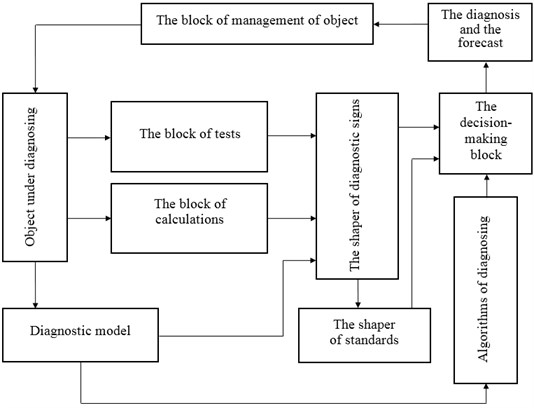
The theoretical basis of the proposed methods and means to improve machines vibration diagnostics are solving the problem of natural frequencies and modes of its vibrations through calculating the levels of power ratio (sensitivity functions) parts of the equipment in computer program [10]. Energy ratings depending on the parameters of the diagnosis objects (mathematical and physical) are defined by the solutions of this problem, the calculated energy spectra are considered as a priori basis of the designed system of technical diagnostics of power equipment, and regimes of its vibration diagnostic control are chosen.
Considering the mathematical model of free vibrations of the system of any nature, complexity, structure and using the Rayleigh method one can express the maximum levels of kinetic (magnetic) and potential (electrical) energy, and determine the natural frequency by considering the energy balance of the system under certain assumptions about its deformation and the sensitivity function to defects manifestation (resonant excitation) for the j-th natural frequency of the variation of inertia (inductive) and elastic (electrical capacitance) parameters of electrical, hydraulic and mechanical systems [2]:
where , – the maximum values of the kinetic (magnetic) energy of mass (inductance) and the whole system at the natural frequency of vibrations ; , – the maximum values of the potential (electrical) energy of -th site and the whole system at the natural frequency of vibrations ; – moment of inertia (mass, acoustic mass, inductance) of -th element; – stiffness (acoustic stiffness, the inverse of the capacitance) of -th site.
Energy modes representing the vertical segments of the corresponding deferred inertial or elastic element of the system clearly indicate the level of sensitivity of the details to the emergence and development of damages (Fig. 3) [10].
For practical purposes of diagnosing machines as diagnostic information it is necessary to use energy mode parameters (Fig. 3) due to the fact that the anti-nodes and nodes of the usual modes of natural vibrations (Fig. 4) are not always highly sensitive sites, respectively, to the excitation of vibrations and the emergence of damages (including cracks). Analyzing the natural torsional vibrations of shafting machines a diagnostician should take into consideration the fact that the best place and the direction of the excitation is the point in the area of the energy-intensive element of the vibration energy mode of the system and the direction in which the vibrations will be maximum [2, 10].
Fig. 3The energy modes of shafting torsional vibration of gas compressor unit EGCU2-12.5/76-1.5 model with a birth defect (structural type) in the tooth-type coupling TTC-1 with rubber elements at the first natural frequency: a) and b) at f1= 23.3 Hz (torsional stiffness coupling TTC-1 c19-20= 5.7∙106 N∙m/rad); c) and d) at f1= 8.5 Hz as a result of degradation (including aging) of the elastic properties of the coupling TCC-1 to c19-20= 0.5∙106 N∙m/rad; a) and c) – inertial elements energy modes; b) and d) – elastic elements energy modes; Qm1 and k1 – generalized coordinates and numbers of shafting elastic regions on the 1-st mode of natural vibrations
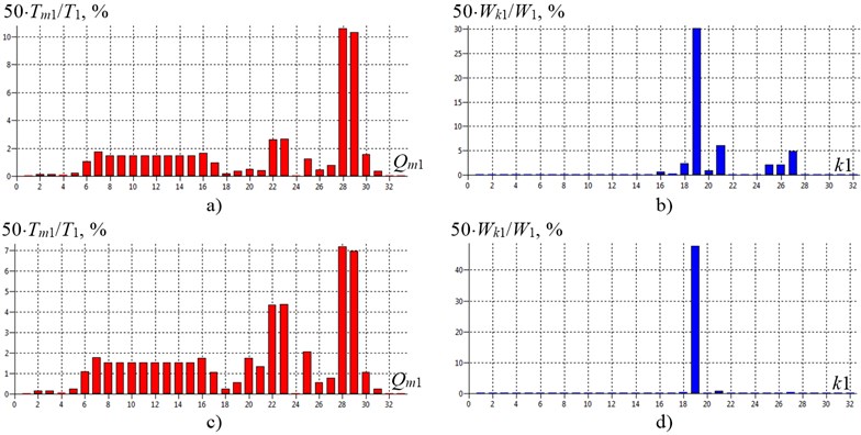
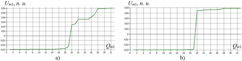
Fig. 4The usual modes of shafting torsional vibration of gas compressor unit EGCU2-12.5/76-1.5 model with a birth defect (structural type) in the tooth-type coupling TTC-1 with rubber elements at the first natural frequency for natural normalization of the amplitudes of the generalized coordinates: a) at f1= 23.3 Hz (torsional stiffness coupling TTC-1 c19-20= 5.7∙106 N∙m/rad); b) at f1= 8.5 Hz as a result of degradation (including aging) of the elastic properties of the coupling TCC-1 to c19-20= 0.5∙106 N∙m/rad; Um1 – the amplitude of the generalized coordinates Um1on the 1-st mode of natural vibrations; n.u. – natural units
To sum up the absence or presence of a defect and its development it is necessary to compare a calculated priori information (calculated energy spectra determined by a computer program) with a posteriori one on the basis of vibrational channel. The main units of equipment that are prone to the defects birth have maximum levels of power ratio at the natural frequencies. The occurrence of the defect is determined by the appearance of vibration amplitudes of equipment units high-energy at the natural frequencies of the object being diagnosed. The development of the defect is defined by the difference between the amplitudes of the vibrations of equipment units high-energy at the natural frequencies of the object under diagnosing, measured at different times (direct spectra) and/or the spectrum of the signal envelope.
The level of the amplitudes of forced vibrations (the response of the system to the origin of the defect) is determined by energy sensitivity to the excitation (sensitivity function), the size of the defects, the level of damping in the system and its natural frequencies encroachment of vibration from the frequencies disturbance.
4. Application of methods and means of increasing the efficiency of vibration diagnostics
Methods and means testing based on mathematical modeling was performed on the test bench set, consisting of marine diesel 8FS16.5/18.5 (power 441.3 kW at engine speeds 1750 rev/min), a flexible coupling ST.16.07.SB and inductor brakes W700. Shafting torsional vibration measurement of bench set was made on the free end of the crankshaft of the engine (in the first inertial mass of the system) using inertial type of radio torsiograf constructed by FSUE “Krylov State Research Center” (St. Petersburg, Russia). In torsiograf a capacitive method converting angular displacement of the inertial mass into an electrical signal is used; the signal being transmitted to the recording device along a radio channel at the frequency 660 kHz. A comparison of the calculated and experimental data on the bench set shafting torsional vibration with the marine diesel 8FS16.5/18.5 allows to come to the conclusion about the correctness of the mathematical model of torsional vibrations and appropriate diagnosis of emerging and developed defects according to the developed methods and means [5, 10].
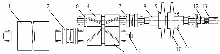
This innovative technology is also applied to establish the causes of failures (the appearance of significant defects of major units) machines EGCU2-12.5/76-1.5 (Fig. 1) and to increase the reliability of their operation. EGCU2-12.5/76-1.5 is used for the compression of natural gas transported through pipelines and consists of a synchronous electric motor SDG-12500 (capacity of 12,500 kW at motor speeds 3000 rev/min), the multiplier and the centrifugal compressor C-285-22-1 (at 5000 rev/min) (Fig. 5). Repeated setting (welding) of teeth gear couplings connecting the rotor of the motor and the shaft-wheel multiplier of gas compressor unit took place when the service life of damaged components was in the range of 3,104 to 27,233 hours of machine time at the park resource of gear coupling 50,000 hours of machine time (number of starts of the machines to units damage ranges from 16 to 44). In this case, the analog (lubrication oil temperature, bearings, natural gas, vibration housings and shafts, lubrication oil pressure, natural gas, etc.) and discrete (fire, emergency stop, accidentally closing the tap number 1 or number 2, etc.) settings of emergency and warning system for automatic control of machinery were in the acceptable range.
Fig. 5The design of shafting of gas compressor unit EGCU2-12.5/76-1.5: 1 – rotor of the main electric motor (MEM); 2 – tooth-type coupling number 1 with or without rubber elements (TTC-1); 3 – shaft-wheel multiplier (М); 4 – gear shaft multiplier; 5 – main oil pump lubrication; 6 – wheel device to rotate the shaft line; 7 – tooth-type coupling number 2 (TTC-2); 8 – centrifugal compressor (CC) rotor; 9 – impeller stage 1; 10 – impeller stage 2; 11 – balance chamber; 12 – tooth-type coupling number 3 (TTC-3); 13 – main oil pump seals
Computer construction of a mathematical model of the object under diagnosing was performed on the results of the calculation of its dynamic parameters using the technical data and drawings and design documentation [10] (Fig. 6).
Fig. 6The shafting torsional vibration model of gas compressor unit EGCU2-12.5/76-1.5 with a centrifugal compressor C-285-22-1: Jm and Ck – axial moments of inertia of the m-th concentrated mass (details) and torsional stiffness k-th elastic portions of shafts; MEM – the main electric motor; TTC-1 – tooth-type coupling number 1 with or without rubber elements; М – multiplier; TTC-2 – tooth-type coupling number 2; I – impellers of the 1st and the 2nd stage of centrifugal compressor; BC – balance chamber; TTC-3 – tooth-type coupling number 3; 24 – main oil pump lubrication; 25 – wheel device to rotate the shaft line; 33 – main oil pump seals; M7 – M16 and M28, M29 – moments acting on the rotor of the motor and the rotor of the centrifugal compressor (excite torsional vibrations); Mс7 – Mс16 and Mс28, Mс29 – moments damping torsional vibrations
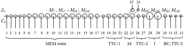
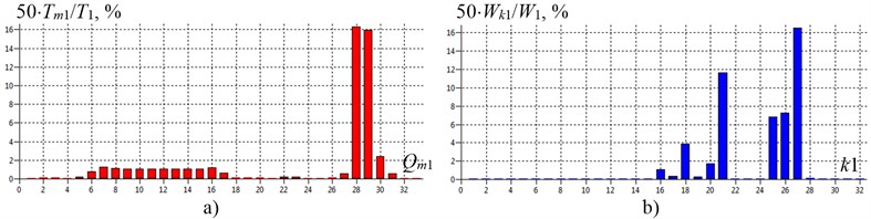
Fig. 7The energy modes of shafting torsional vibration of gas compressor unit EGCU2-12.5/76-1.5 model with the elimination of the defect in the tooth-type coupling TTC-1 (without rubber elements) at the first natural frequency f1= 34.5 Hz (torsional stiffness coupling TTC-1 c19-20= 1.0∙109 N∙m/rad): a) – inertial elements energy mode; b) – elastic elements energy mode; Qm1 and k1 – generalized coordinates and numbers of shafting elastic regions on the 1-st mode of natural vibrations
Diagnosis, prognosis, and the signal control of the machine were carried out through comparing the calculated values (Fig. 3, 5, 6) [10] and experimental information (Fig. 1) of gas compressor unit EGCU2-12.5/76-1.5 failures:
1. The use of rubber in gear coupling TTC-1 of gas compressor unit has reduced shock loads on the teeth of the coupling during direct asynchronous start of the machine (in the initial period of operation), but gas compressor unit shafting torsional vibrations in the starting and operating conditions were not to reduce: calculated natural frequency of the torsional vibrations of the system are in the range of 23.3 Hz and 6455.2 Hz; during the degradation of the elastic properties of the toothed coupling TTC-1 the lowest frequency 23.3 Hz is greatly reduced to values 8.5 Hz and below, the most energy-intensive units in the first two modes are the inertia of the MEM rotor, impellers of the 1st and the 2nd stage of centrifugal compressor and gear coupling stiffness TTC-1. Contact stresses at the interface gearing TTC-1 were significantly increased due to hit in to the near-resonant zone of shafting torsional vibrations (not transmitted to the bearings during normal operation of the machine) in the process of generating vibrations of natural gas in the centrifugal compressor – the trail of gas pipelines system, including about unit surging (and as a consequence to a significant heating of the rubber elements, their disintegration and the adhesion to the metal coupling parts, metal chipping, pitting and welding of teeth coupling TTC-1).
2. According to [10] the energy spectra of shafting torsional vibration in the absence of the rubber components in the gear coupling was calculated (estimated frequency of natural vibrations of system range from 34.5 Hz to 6451.9 Hz), thus reducing the gear coupling TTC-1 elastic parameter energy intensity on the first two modes and tuning a system from torsional vibrations of near-resonant excitation (Fig. 7).
3. To reduce the contact stresses in the areas of gas compressor unit interfacing gearing (in transient dynamic conditions of the machines) it was decided to withdraw the rubber components in the gear coupling TTC-1 from the operation, resulting in improved resource units of the equipment and eliminate failures and machines downtime due to the occurrence hazardous near-resonant torsional vibration of machines shafting.
Thus, the use of energy modes parameters of gas compressor units shafting torsional vibration allowed to increase the level of reliability of the gas compressor units design with a minimum of complexity of diagnostic work.
5. Conclusions
The developed methods and means based on mathematical modeling have improved the vibration diagnostics of power equipment detecting defects and eliminating the causes of damage of the equipment units. In order to recognize the birth of defects in the structure of machinery it is necessary to monitor and analyze the technical condition of power equipment on torsional vibration of shafts using of torsiografs, strain gauges and/or other means. This requires the development and use of the machines staffing by the built-in means for measurement and analysis of torsional vibrations of rotors (such as encoders, different principles of action, including optical, magnetic, magnetic resistors, electromagnetic acoustic and/or other converters) and emergency protection with the use of the proposed innovative technology.
The economic feasibility of repairs in terms of the technical condition of gas compressor units with the diagnosis of the technical condition for torsional vibration is to increase the reserve maintenance periods, reducing the volume of repairs, advance planning of specific details repairs, increasing the reliability of the machines.
References
-
V. V. Kluev, G. Zusman. Nondestructive Testing and Diagnostics: Handbook. RSNTTD and Metrix Instrument Co., Moscow-Houston, 2004, p. 656.
-
Reshetov A. A., Arakelyan A. K., ed. prof. Arakelyan A. K. Non-Destructive Testing and Ttechnical Diagnostics of Power Facilities: Manual. Publishing House “Chuvashskiy Universitet”, Cheboksary, 2010, p. 470.
-
Scientific and Technical Policy of Gazprom in the Gas Compressor Units up to 2020. LLC “Scientific-Research Institute of Natural Gases and Gas Technologies – Gazprom VNIIGAZ”, Moscow, 2010, p. 15.
-
Sokolova A. G., Balitskiy F. Ya., Dolaberidze G. V., et al. Vibration monitoring the state of the gas turbine engine DG-90 on multivariate discriminant analysis. Bulletin of the Scientific and Technological Development. National Technology Group, Vol. 2, Issue 42, 2011, p. 47-56.
-
Reshetov A. A. The methods and means of improving the efficiency of gas transmission systems power equipment vibration monitoring. Testing. Diagnostics, Vol. 9, 2012, p. 32-41.
-
Ragulskis Kazimieras. Some problems of nonlinear precise vibromechanics and vibroengineering (summary). Journal of Vibroengineering, Vol. 13, Issue 3, 2011, p. 590-618.
-
Kiselev M. I., Zroychikov N. A., Pronyakin V. I., et al. Precision study of the work of the turbine unit by optical-electronic means. Combined Heat and Power, Vol. 11, 2006, p. 10-13.
-
ISO 22266-1:2009. Mechanical Vibration – Torsional Vibration of Rotating Machinery – Part 1: Land-Based Steam and Gas Turbine Generator Sets in Excess of 50 MW, 2009, p. 25.
-
Trethewey, M. W., Lebold, M. S., Turner, M. W. Minimally Intrusive Torsional Vibration Sensing on Rotating Shafts. IMAC Conference and Exposition on Structural Dynamics, USA, 2010.
-
Reshetov A. A., Zakharov N. A. The Program-Technical Means of Improving Vibration Monitoring (PTM IVM) Power Equipment. Chuvashia Republican Regional Rranch of the RSNTTD, Cheboksary, 2013.
About this article

