Abstract
The impact vibration between shrouded blades under a multiple-harmonic excitation in an aircraft engine is analyzed in this paper to study the influence of parameters on dynamic behavior of the system. Aircraft engine blades undergo high vibrations caused by the centrifugal forces and gas forces during operation. The blade vibrations lead to high dynamic stress that causes high cyclic fatigue failure. In order to reduce the dynamic stress, a common technology is adding a shroud to each blade to generate a new damping from impact and friction between the shrouds. To investigate the impact vibration, a model composed of springs and a cantilever beam with a lumped mass is developed to simulate the cyclic symmetry structure of the shrouded blade in aircraft engines. The model is exerted a multiple-harmonic excitation to simulate the centrifugal force and the gas force during operation. Adopting multiple-harmonic excitation is closer to reality than harmonic excitation. The Euler-Bernoulli beam theory is utilized in deriving the equation of motion and the associated boundary conditions. Employing the Galerkin’s method, an approximate analytical solution is obtained by using the Fourier series method. Explicit expressions are obtained to calculate the responses of the system. Based on the expressions, parametric analysis is conducted to study the effect of the gap between shrouds, the mass ratio of the shroud to the blade and the stiffness ratio on the responses of the system. The numerical results indicate that there is an optimum mass ratio that makes the amplitude of the response lowest; the gap between shrouds and the stiffness ratio have effects on the responses and the resonance frequencies of the system. The analytical method used here for the approximate analytical solution can be extended to study other continuous systems.
1. Introduction
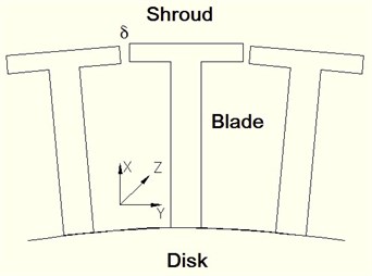
In aircraft engines, blades are a major component. Blade failure accounts for most of the failures in aircraft engines. Blade failure occurs as a result of high cyclic fatigue caused by high dynamic stress. High dynamic stress results from severe blade vibrations when blades rotate at a high speed during operation. To reduce the blade vibration, a common technology is to add a shroud to each blade, as shown in Fig. 1; this is because shrouds collide with each other during operation, generating new damping from impact and friction. Such technology has been widely used in aircraft engines and has been proven to be effective in vibration reduction.
To facilitate the design of the shrouds to achieve optimal vibration reduction, it is essential to study dynamic characteristics of the friction and impact between the shrouds. In the past several decades, both model construction and solution methods have been developed to analyze the dynamic behavior of the shrouded blade. Yang B. D. and C. H. Menq [1] researched on a 3-D friction contact model of turbine blade, which consists of three states: the stick, slip and separation during a cycle of oscillation. The researchers developed a transition criterion among the three states and produced the hysteresis loop to characterize the equivalent damping and stiffness of the friction contact. Other friction contact models [2-3] and full cycle model of turbine blades [4] were developed to conduct dynamic analysis of the system and much progress was obtained in the research work. Choi and Y.-T. Chou [5] developed a pre-twist model of turbine blade with varying cross-section, where the shroud is treated as a mass. The researchers proposed the Modified Differential Quadrature Method (MDQM) for vibration analysis of the turbo-machinery blades; and the method was demonstrated as an accurate and effective method by comparing with analytical solutions. Menq C. H., Chidamparam P. and Griffin J. H. [6] presented an approximate method for analyzing the 2-dimensional friction contact and analyzed the influence of friction coefficient between interfaces on the vibration characteristic of the system. Many researchers also focused on stability [7-9] and mistuning [10-12] of the system and got a lot of achievements. Bo Wun Huang [13] studied the effect of the number of blades and distribution of cracks on vibration localization in a cracked pre-twisted blade system; the shroud segments between the blades are regarded as springs. The research result reveals that the number of the grouped blades and distribution of the multi-disordered may markedly affect the localization phenomenon. Dong-Ho Rhee and Hyung Hee Cho [14] investigated the effect of the blade position on heat transfer in a blade and shroud. The result shows that the heat transfer on the tip and the shroud was significantly affected by the blade position because the incoming flow condition is changed. Ibrahim Ata Sever [15] carried out experiments via a test rig to validate the numerical models developed for blade vibration response predictions at Imperial College. The tests demonstrated that the numerical model was able to predict the responses of the blisks for several mistuning patterns when fitted with the friction dampers. J. J. Kielb and R. S. Abhari [16] focused on the aerodynamic and structural damping in shrouded blades. Corso Padova and Jeffery Barton [17] investigated the aeromechanic phenomena for the gas turbine engines by an experiment method and analyzed the nonlinear dynamic response. Nan et al. [18] developed a spring-mass model to study the effect of the parameters of the system such as the gap between shrouds, contact angle, the friction coefficient and the stiffness ratio, on the dynamic characteristics of the shrouded blades. J. J. Chen et al. [19] predicted the periodic response of the blades with the nonlinear shroud constraints by employing a three-dimensional contact model and analyzed the resonant frequency shift, the damping effect and the jump phenomenon caused by the nonlinear shroud constraints. Petrove P. et al. [20] developed a friction model for analysis of the bladed disks in the time domain, the model allows one to consider time-varying friction contact parameters and anisotropy, and variations of the friction are taken into account. S. K. Sinha et al. [21] derived the dynamical equations for a rotating radial cantilever blade in a centrifugal force field. The equations include the gyroscopic moments and internal material damping in the shaft and the external damping in the bearing. Mathias Legrand et al. [22] researched on a specific interaction due to radial rub between a bladed disk and surrounding casting. The blade of the tuned assembly is represented by a rigid body and the stiffening due to centrifugal force is neglected as well as gyroscopic effects. Equations are developed and solved by harmonic balance method. Ha Seong Lim et al. [23] carried out modal analysis of a rotating multi-packet blade system. Blades are modeled as cantilever beam and the shroud are treated as springs. However, the model does not describe the separation and impact between blades. Paolo Bisegna et al. [24] researched on the vibration localization phenomenon in disordered structure based on a model which is composed of a pendulum equipped with springs. Some expressions are got to show how the feature of the mistuned structure depends on the physical parameters. However, the model does not present the interaction between shrouds as well as reference [23]. Shiming Chu et al. [25] studied the impact vibration and nonlinear behavior of shrouded blade with asymmetric gaps under wake flow excitations. The Frobenius method is employed to determine the dynamic frequencies. However, the shroud is treated as rigid body and the influence of the mass of the shroud and on the vibration is not investigated.
Although much research has been done on the dynamic behavior of the shrouded blade systems, most studies focused only on the friction between shrouds with relation to the friction contact performances. The impact vibration between the shrouds has not been studied by an analytical method in the published articles. The mass of shroud is often neglected and the effect of the shroud mass on the dynamic characteristics is not considered. This paper will address the lack of the research in the impact vibration between shrouds and the effect of shroud mass on the dynamic characteristics of the system by a rigorous analytical method.
To investigate the impact vibration, a model composed of springs and a cantilever beam carrying a mass is developed to simulate the cyclic symmetry structure of the shrouded blade in aircraft engines. Few researchers treated the shroud of the blade system as a lumped mass with which the model is closer to the reality. The shrouded blades undergo centrifugal forces and the gas excitation during operation. Consequently, a multiple-harmonic excitation is exerted on the model to simulate the centrifugal forces and the gas excitations. The Euler-Bernoulli beam theory is used in deriving the equation of motion and the associated boundary conditions. Employing the Galerkin’s method, an approximate analytical solution is obtained by using the Fourier series method. Explicit expressions are obtained to calculate the responses of the shrouded blade system. Based on the expressions, parametric analysis is performed to study the effect of the stiffness ratio, the mass ratio and the gap between shrouds on the steady-state responses of the system.
Fig. 1Schematic view of the shrouded blades of aero-engines
2. Modeling and equations of motion
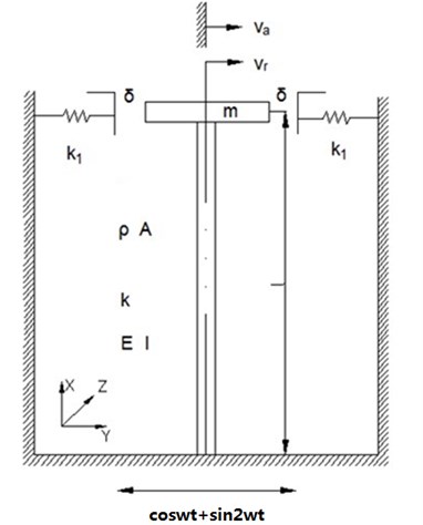
To study the impact vibration of a shrouded blade, a model comprised of springs and a cantilever beam with a concentrated mass is developed to simulate the shrouded blade with rectangle shroud. For simplicity, the blade is approximated as a cantilever beam, and the shroud is equivalent to an added mass . The stiffening due to centrifugal forces is neglected as well as gyroscopic effects. The shrouds impact each other if the system is subjected to a multiple-harmonic excitation which is large enough. The coordinate system is defined in accordance with the radial (), transverse () (i.e. tangential direction) and axial () directions, as shown in Fig. 2. Accordingly, the shrouded blades have vibrations in the radial, transverse and axial directions. The axial vibration is neglected because it is almost equal to zero for the blade with a rectangle shroud.
Model is built and shown in Fig. 2; it shows a cantilever beam with a tip mass , representing the blade and the shroud. The shrouded blades undergo the centrifugal force and the gas excitation during operation. Therefore, a multiple-harmonic excitation is exerted on the model to simulate the centrifugal force and the gas excitation. When the model is subjected to a displacement excitation the mass vibrates and collides with the adjacent springs on both sides of the mass. The beam is regarded as an Euler-Bernoulli beam. The center of the added mass coincides with the attachment point of the beam centerline and the tip mass. Parameters , , , ,,, and stand for the mass density of the beam, the cross-sectional area, the stiffness of the beam , the flexural rigidity of the beam, the impact stiffness between shrouds, the length of beam, the gap between shrouds and the added mass. and represent the radial displacement and the transverse displacement of the beam, respectively; and denote the absolute displacement and the relative displacement of the beam in the transverse direction, respectively.
For the cantilever beam with a tip mass, the kinetic energy is:
where denotes the displacement at the free end of the beam, and denote the derivatives of with respect to , respectively. The potential energy of the beam is:
where represents the derivatives of with respect to . Using the Hamilton's principle:
Fig. 2Analytical model of shrouded blade
The governing equations in the radial and transverse directions are:
In comparison with the radial and axial vibrations, the transverse vibration (-direction) is the focus here because it is the dominant vibration for the blade with a rectangle shroud. The governing equation of the beam for the absolute displacement in the transverse direction can be simplified by neglecting and as follows:
The relationship between the absolute displacement and the relative displacement is:
Substituting Equation (7) into (6) leads to the governing equation of the beam for the relative displacement in the transverse direction:
The corresponding boundary conditions are:
The restoring force of the spring is represented as:
where is the relative displacement of the beam at the free end ().
3. Solutions
Fourier series method is adopted to solve the equation of motion with the boundary conditions. The solution can be assumed as a series in terms of an undetermined shape function with a given corresponding weighting coefficients. The shape function has four coefficients to be determined. However, the boundary conditions consist of a restoring force of the springs, which is piecewise-linear because of the gap between shrouds. It is difficult to determine directly the solution of the equation of motion. In this article, the restoring force of the spring is assumed to be a periodic function and it can be written as the form of Fourier series. Therefore, the governing equations of the beam with a mass can be solved by using the Fourier series method.
Assuming the solution for Equation (6) as:
According to Equation (7), the relative displacement is:
where:
Equation (13) can be rewritten as followings due to the piecewise-linear characteristics:
where represents the maximum displacement of the beam at the free end.
The restoring force can be denoted as with the period and a phase lag angle ; and a new angle is defined as:
And then is denoted as the form of :
where denote six motion states: state 1 that is from the right critical position, i.e. between without impact and with impact, to the right maximum displacement position; state 2 that is from the right maximum displacement position to the right critical position; state 3 when the beam with tip mass vibrates left and has no impact with spring; state 4 that is from left critical position to the left maximum displacement position; state 5 that is from left maximum displacement position to left critical position; state 6 when the beam with tip mass vibrates right and has no impact.
Switching over the motion states from one to another among six states is as follows:
is given by means of the Fourier series expansion:
Neglecting the terms of orders higher than one:
Using Equations (15) and (9), the coefficient is obtained:
Using Equations (15) and (10), the coefficient is obtained:
Substituting Equations (28) and (29) into Equation (15):
Substituting Equation (30) into boundary condition Equations (11) leads to equations in the form of and :
Substituting Equations (27) and (30) into boundary condition Equation (12) yields another equation in the form of and :
Applying Equations (31) and (32), the coefficients and can be derived as:
where:
By using equation (35), (38) and (39), the displacement at the position from the clamped end is represented as:
Accordingly, let , the displacement at the free end of the beam is obtained:
where:
From equations (25)-(27) and (50), the following equations are obtained:
Applying equation (51), let the maximum amplitude of the beam at the free end be :
Using equation (53):
Equation (14) can be nondimensionalized as:
where:
Multiplying both sides of Equations (57) by and respectively, and integrating through the whole period of , the nondimensional coefficient and are obtained as follows:
The nondimensional amplitude at the free end of the beam is:
where:
4. Numerical results and discussion
Based on the expressions derived in Section 3, the numerical calculations are conducted in this section. The influence of such parameters as the gap between shrouds , the mass ratio of the added mass to the beam mass and the stiffness ratio on the dynamic responses at the free end of the beam is investigated in this section.
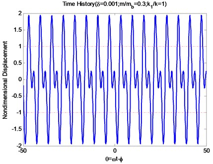
Fig. 3 shows a time history signal of the beam with a tip mass at the position under the following parameters: the gap between shrouds m, the ratio of the added mass to the beam mass 30 % ( denotes the mass of the beam, ), the stiffness ratio, i.e. the spring stiffness divided by the beam stiffness 1, the length of the beam 0.2 m, Young's modulus 210 GPa, the second moment of inertia , the density of the beam 7800 kg/ and the frequency of excitation 325. The dashed line in the figure denotes the critical condition between with impact and without impact. There is no impact between the two dashed lines and there are impacts when the displacement is above 1 or below –1. It can be seen from Fig. 3 that there is a double frequency as a result of the multiple-harmonic excitation.
Fig. 3Time history of the beam at the free end
4.1. Gap Between Shrouds
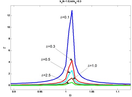
Fig. 4 shows how the nondimensional amplitude at the free end of the beam changes with the various frequency ratios under the different values of the gap between shrouds : 0.1 mm, 0.3 mm, 0.5 mm, 1.0 mm, 2.5 mm. Other parameters of the system are chosen as: the length of the beam , Young's modulus , the second moment of inertia , the density of the beam , the stiffness ratio 1, the mass ratio 0.3. It can be seen from Fig. 4 that the nondimensional amplitude is getting smaller as the gap between shrouds increases around the range from 0.1 mm to 2.5 mm when the other parameters are fixed. However, the relation between the gap and the amplitude is not linear. For the shrouded blades, the contact force which is approximated to the spring force is actually the constraint force. Different gaps lead to different moments when the constraint forces exert the shrouded blade; and lead to different contact states, especially the vibration shape for shrouded blade. Therefore, the relation (as seen in Fig. 4) between the gaps and the amplitudes emerges. In addition, the resonance frequency remains constant for the various gaps. It is reasonable to the fact that the gaps, i.e. one kind of the initial states, do not change the natural characteristics. The research on the influence of the gap gives an approach to analyze quantitatively responses and design the gap of the blade system.
Fig. 4The influence of the gaps between shrouds on the response
4.2. Mass ratio
Fig. 5 shows how the nondimensional amplitude at the free end of the beam varies with the frequency ratios under the different values of the mass ratio : 0.1, 0.3, 0.5, 0.7, 1.2. Other parameters of the system are chosen as: the length of the beam 0.2 m, Young's modulus , the second moment of inertia , the density of the beam , the stiffness ratio 1. It can be seen from Fig. 5 that the nondimensional amplitude is getting smaller as the mass ratio increases from 0.1 to 0.3 when the other parameters are fixed; and then the amplitude increases as the mass ratio increases from 0.3 to 0.5.
Fig. 5The influence of the mass ratio on the responses
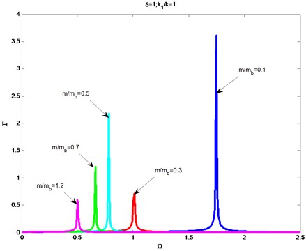
Finally, the amplitude decreases as the mass ratio increases from 0.5 to 1.2. It indicates that the mass of the shroud affects the dynamic characteristic of the shrouded blade system; and how to affect is much complicated. In this article, the mass of the shroud is regarded as a tip mass and it is related to the boundary condition. Different mass ratios lead to different boundary conditions and then lead to different vibration amplitudes. There are two values of 0.3 and 1.2 when smaller amplitudes of vibration can be got. Because the mass of shroud is bigger than the blade when 1.2, it is unavailable to adopt this value for an optimal shroud. Accordingly, there is an optimal value of 0.3 for a best effect of vibration reduction. Moreover, the resonance frequency decreases as the mass ratio increases. It is in accordance with the fact that the natural frequency is related to the mass and stiffness of the system. For the shrouded blade system, changing shroud means changing the mass of the system. Consequently, the resonance frequency is changed. The research on the influence of the mass ratio is essential to reduce vibrations and design shrouds.
4.3. Stiffness ratio
Fig. 6 shows how the nondimensional amplitude at the free end of the beam changes with the various frequency ratios under the different values of the stiffness ratio : 0.2, 0.6, 1.0, 1.4, 1.8. Other parameters of the system are chosen as: the length of the beam 0.2 m, Young's modulus 210 GPa, the second moment of inertia , the density of the beam , the mass ratio 0.3. It can be seen from Fig. 6 that the nondimensional amplitude is becoming smaller as the stiffness ratio increases around the range from 0.2 to 1.8 when the other parameters are fixed. Increasing stiffness ratio means 1) increasing only, 2) decreasing only or 3) increasing the ratio value of to . For the situation 1) increasing means increasing the constraint force of the system, which restricts the vibration of system; for the situation 2) decreasing leads to decreasing the natural frequency of the system, vibration characteristics of the impact is changed; the situation 3) is similar to the situation 2). When the stiffness ratio increases from 0.2 to 0.6, the amplitudes decrease sharply and then decrease moderately when the stiffness increases from 0.6 to 1.8.
Fig. 6The influence of the stiffness ratio on the responses

It is not appropriate choice that the stiffness ratio 0.2 is selected as the parameter of design, because of the bad effect of vibration reduction. In addition, the resonance frequency increases as the stiffness ratio increases. Increasing the stiffness ratio is actually to increase the relative stiffness of the system. Therefore, the resonance frequency increases. The research on the influence of the stiffness ratio gives an approach to analyze quantitatively responses and design the stiffness of the blade system.
5. Conclusions
The impact vibration of the shrouded blades for aircraft engines under a multiple-harmonic excitation is studied and the parametric analysis of the shrouded blade system is conducted to investigate the influence of the stiffness, the mass ratio and the gap between shrouds on the steady-state responses of the system. An analytical model composed of springs and a cantilever beam carrying a lumped mass is developed to simulate the cyclic symmetry structure of the shrouded blade system. The model is exerted multiple-harmonic excitation forces to study the centrifugal force and the gas force during operation. The Euler-Bernoulli beam theory is utilized in deriving the equation of motion and the associated boundary conditions. An impact cycle is divided into six states to analyze the transition from one state to another state. An approximate analytical solution is obtained by using the Fourier series method. The major conclusions that can be drawn from this research work are given as follows:
(1) The gap between shrouded blades in aircraft engines has significant influence on the dynamic behavior of the system. The amplitude of vibration for the shrouded blades is becoming smaller as the gap increases around certain range; and the relation between gap and amplitude is not linear. The gap affects amplitude of the shrouded blade system by changing the contact moment. The resonance frequency remains constant for the various gaps. This research on the influence of the gap gives an approach to analyze quantitatively responses and the research gives a direction to design the gap of the system.
(2) The influence of the mass ratio of the shroud to the blade on the amplitude of the vibration is much complicated. The mass ratio affects the dynamic characteristics by changing the boundary conditions. There is an optimal value of the mass ratio 0.3 to get a best effect of vibration reduction. The resonance frequency decreases as the mass ratio increases. The research on the influence of the mass ratio is essential to design the damper mass and to get a good damping effect.
(3) The ratio of the impact stiffness to the blade stiffness has important effect on the dynamic characteristics of the system. The amplitude of the vibration for the system decreases as the stiffness ratio increases. The three situations of increasing stiffness ratio are discussed and the causes of the amplitude change are analyzed. The resonance frequency increases as the stiffness ratio increases. The research on the influence of the stiffness ratio presents a method to analyze quantitatively response and resonance frequency for designing the stiffness of the shrouded blade system.
(4) The parameters of the shrouded blade system: the gap between shrouds, the ratio value of the impact stiffness to the blade stiffness and the mass ratio of the shroud to the blade all affect the effect of vibration reduction. It is necessary to consider the parameters overall and adopt a prudent design of the parameter for the shrouded blade system. The approach used in this paper for the approximate analytical solution can be extended to study other continuous systems.
References
-
Yang B. D., Menq C. H. Characterization of 3D contact kinematics and prediction of resonant response of structure having 3D friction constraint. Journal of Sound and Vibration, Vol. 217, Issue 5, 1998, p. 909-925.
-
K.-H. Koh, J. H. Griffin, S. Filippi, A. Akay. Characterization of turbine blade friction dampers. Transactions of the ASME, Vol. 127, 2005, p. 856-862.
-
M. Allara. A model for the characterization of friction contacts in turbine blades. Journal of Sound and Vibration, Vol. 320, 2009, p. 527-544.
-
Gwo-Chung Tsai. Rotating vibration behavior of the turbine blades with different groups of blades. Journal of Sound and Vibration, Vol. 271, 2004, p. 547-575.
-
S.-T. Choi, Y.-T. Chou. Vibration analysis of elastically supported turbo-machinery blades by the modified differential quadrature method. Journal of Sound and Vibration, Vol. 2, 2001, p. 5.
-
Menq C. H., Chidamparam P., Griffin J. H. Friction damping of two dimensional motion and its application in vibration control. Journal of Sound and Vibration, Vol. 144, Issue 3, 1991, p. 427-447.
-
Y. N. Al-Nassar, M. Kalyon, M. Pakdemirli. Stability analysis of rotating blade vibration due to torsional excitation. Journal of Vibration and Control, Vol. 13, Issue 9-10, 2007, p. 1379-1391.
-
G. Genta. On the stability of rotating blade arrays. Journal of Sound and Vibration, Vol. 273, 2004, p. 805-836.
-
Bo-Wun Huang, Jao-Hwa Kuang. Variation in the stability of a rotating blade disk with a local crack defect. Journal of Sound and Vibration, Vol. 294, 2006, p. 486-502.
-
J. A. Kenyon, J. H. Griffin. Forced response of turbine engine bladed disks and sensitivity to harmonic mistuning. Journal of Engineering for Gas Turbines and Power, Vol. 125, 2003, p. 113.
-
Yum Ji Chan. Variability of Blade Vibration in Mistuned Bladed Discs. A Thesis submitted to the University of London for the Degree of Doctor of Philosophy, Department of Mechanical Engineering, Imperial College, London, October 2009.
-
D. M. Feiner, J. H. Griffin. A fundamental model of mistuning for a single family of modes. Journal of Turbomachinery, ASME, Vol. 124, 2002, p. 597-605.
-
Bo-Wun Huang. Effect of number of blades and distribution of cracks on vibration localization in a cracked pre-twisted blade system. International Journal of Mechanical Sciences, Vol. 48, 2006, p. 1-10.
-
Dong-Ho Rhee, Hyung Hee Cho. Effect of vane/blade relative position on heat transfer characteristics in a stationary turbine blade: Part 1. Tip and shroud. International Journal of Thermal Sciences, Vol. 47, 2008, p. 1528-1543.
-
Ibrahim Ata Sever. Experimental Validation of Turbomachinery Blade Vibration Predictions. A Thesis submitted to the University of London for the Degree of Doctor of Philosophy, Department of Mechanical Engineering, Imperial College, London, March 2004.
-
J. J. Kielb, R. S. Abhari. Experimental study of aerodynamic and structural damping in a full-scale rotating turbine. Transactions of the ASME, Vol. 125, 2003, p. 102-112.
-
Corso Padova, Jeffery Barton. Experimental results from controlled blade tip/shroud rubs at engine speed. Journal of Turbomachinery, ASME, Vol. 129, 2007, p. 713-724.
-
G. F. Nan, X. M. Ren, S. W. He, Y. F. Yang. Damped vibration characteristics of blades with tips of an aero-engine. Journal of Vibration and Shock, Vol. 28, Issue 7, 2009, p. 135-138.
-
J. J. Chen, C. H. Menq. Periodic response of blades having three-dimensional nonlinear shroud constraints. Journal of Engineering for Gas Turbines and Power, Vol. 123, 2001, p. 901-909.
-
E. P. Petrov, D. J. Ewins. Generic friction models for time-domain vibration analysis of bladed disks. ASME Journal of Turbomachinery, Vol. 126, 2004, p. 184-192.
-
S. K. Sinha. Dynamic characteristics of flexible-bladed rotor with Coulomb damping due to tip rub. Journal of Sound and Vibration, Vol. 273, 2004, p. 875-919.
-
M. Legrand, C. Pierre, B. Peseux. Structural modal interaction of a four degree-of-freedom bladed disk and casing model. ASME Journal of Computational and Nonlinear Dynamics, Vol. 5, 2010, p. 041013-1-041013-9.
-
H. S. Lim, J. Chung, H. H. Yoo. Modal analysis of a rotating multi-packet blade system. Journal of Sound and Vibration, Vol. 325, Issue 3, 2010, p. 513-531.
-
P. Bisegna, G. Caruso. Dynamical behavior of disordered rotationally periodic structures: a homogenization approach. Journal of Sound and Vibration, Vol. 330, Issue 11, 2011, p. 2608-2627.
-
S. Chu, D. Cao, S. Sun, J. Pan, L. Wang. Impact vibration characteristics of a shrouded blade with asymmetric gaps under wake flow excitations. Nonlinear Dynamics, Vol. 69, Issue 1, 2013.
About this article

Grateful thanks to the National Natural Science Foundation of China (Grant No. 51305267).
