Abstract
The aerodynamic loads of a wind turbine blade under complicated offshore wind conditions were analyzed using Davenport wind spectrum model, which represents the real working conditions closely. Finite element model of the blade was generated by using UG and ANSYS, and qualitative analysis and quantitative simulation were carried out to investigate the dynamic stability of the wind turbine blade. The numerical results indicate that the blade vibration diverges when the frequency of wind speed is close to the first-order natural frequency of the blade, which eventually leads to the occurrence of instability phenomena. It was also found that both waving amplitude and the maximum Mises stress of the blade increase nonlinearly with the average wind speed. However, the maximum Mises stress increases almost linearly with elastic modulus under vibration divergence. Finally, some characteristics for the critical values of the maximum Mises stress and the stable or/and unstable regions, due to variation of the elastic modulus and the horizontal distance between the blade and the tower frame, were further discussed.
1. Introduction
Wind power, as a major type of clean and renewable energy, has received more and more world attention in recent years [1]. The large wind turbine blade has the characteristics of good flexibility and long span and is often subjected to complicated aerodynamic forces due to special offshore wind fields, which frequently causes the catastrophic of wind generator [2]. In order to make the wind turbine blade work safely under complicated offshore wind conditions, the investigation of its strength and vibration stability is needed urgently.
At present, the research on wind turbine blades is mainly focused on the three areas, namely, vibration characteristics, aerodynamic characteristics of flow field and fatigue damage. In vibration area, Carnegie et al. [3] established pre-twisted blade equations using the method of finite element analysis, and studied the impact of pre-torsional on vibration frequency using Rayleigh-Ritz and Runge-Kutta algorithm; Fadaeinedjad et al. [4] investigated the voltage sag impact on mechanical vibration of wind turbine structure; Arrigan et al. [5] developed a semi-active control algorithm using Semi-Active Tuned Mass Dampers (STMDs) to reduce vibrations in the flapwise direction. In flow area, Sarim [6] considered the design and optimization of airfoils for Horizontal Axis Wind Turbine (HAWT) rotors by using a numerical code; Driss et al. [7] studied the effect of Reynolds number on the aerodynamic characteristics of a horizontal axis wind turbine; Congxin Yang et al. [8] optimized the aerodynamic design of a 2MW HAWT rotor based on Particle Swarm Optimization (PSO) and the HAWT blade theory. In fatigue damage area, Darris et al. [9] discussed the impact of changing load phase angle on fatigue damage of blade, and compared the fatigue damage caused by the load of disguise phase angle and constant phase angle by using finite element analysis method; Jing Wang et al. [10] investigated the generation of load spectrum for epoxy resin blade of a large-scale wind turbine.
It is clear that previous researches are mainly concentrated on mechanical behavior analysis of blade vibration stability under constant wind speed. On the other hand, the researches into dynamic stability region and the qualitative and quantitative relationships among the waving amplitude, maximum Mises stress, average wind speed, and elastic modulus under dynamic instability are relatively limited.
In this paper, based on analysis of aerodynamic loads, periodic wind field model representing the real working conditions was established by Davenport spectrum. Solid model of the blade was built up using Unigraphics NX(UG), which is an interactive CAD/CAM system produced by Siemens PLM Software. Dynamic stability simulation for large horizontal axis wind turbine blades was conducted by using ANSYS, a finite element analysis software produced by ANSYS, Inc. Dynamic stability region of relative parameters was presented. The results provide technical references for the safety design of wind turbine blades.
2. Basic theoretical model
2.1. Random wind speed simulation
According to more than 90 strong wind records measured from different locations and heights in the world, Davenport assumed that the turbulence integral scale of the horizontal gust spectrum is unchanged along the height and average measured wind speeds of different heights above ground. Therefore he put forward horizontal pulsating wind speed spectrum, which can be expressed as [11]:
where is the pulsating power spectrum, is the pulsating wind circular frequency, is the wind speed in ten meters standard height, is the ground roughness coefficient. According to the random vibration theory and the China load specification, the coefficient is written as [12]:
where is the wind shear index obtained from experience.
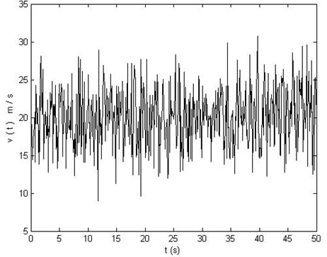
Matlab, which is an interactive advanced scientific computing software produced by MathWorks, is employed to simulate the wind speed spectrum, and 20 m/s average wind speed curve with time is plotted in Fig. 1.
Fig. 1Wind speed time curve at 20 m/s
2.2. Blade aerodynamic loads
Based on momentum blade element theory used to solve the blade aerodynamic loads, the blade is divided into a number of infinitesimal segments called blade element. Suppose the flow between elements does not interfere with each other, and then the blade element is regarded as a two-dimensional blade profile. The blade force can be figured out after the force on blade element is integrated along wingspan direction. For each blade element, the velocity can be separated into and , which are components perpendicular and parallel to rotating surface of the wind wheel, respectively. In detail, the force analysis is shown in Fig. 2.
Fig. 2Airflow speed triangle and aerodynamic component on blade element
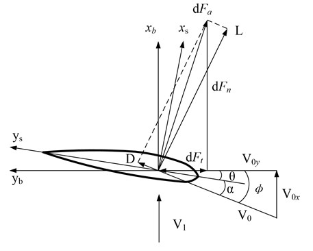
According to momentum theory, aerodynamic force on blade element with a length caused by synthesis airflow velocity , can be divided into normal force and tangential force , and the expressions are given by [13]:
where is the air density, is the section chord length of blade element, and are the lift coefficient and the drag coefficient of blade element airfoil respectively, is the inflow angle of blade element, , and are attack angle and geometric twist angle respectively. The synthesis airflow velocity of blade element can be expressed as:
where , , is the axial induced speed of wind wheel, is inflow wind speed, is the circumferential induced angular velocity at the diameter position of wind wheel, is rotational speed of wind wheel.
2.3. Structural motion equation
Differential motion equation of the blade is:
where , and are mass matrix, damping matrix, stiffness matrix respectively, is blade load vector which can be obtained from formulas (4) and (5). Neglecting the influence of damping on the blade and introducing Newmark method into Eq. (7), one can get [14, 15]:
where is the parameter determined by integral accuracy and stability.
Fig. 3Blade solid model and finite element meshing model
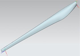
a) Blade solid model
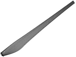
b) Finite element model of entire blade
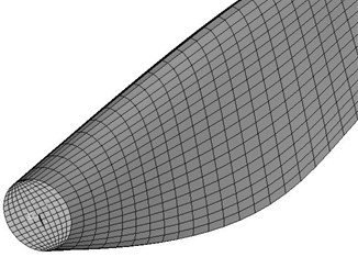
c) Enlarged model
3. Solid modeling and meshing
In this study, airfoil geometry data in reference [16] are used to model blades with a length of 43 meters, and then the blade solid model shown in Fig. 3(a) is generated by using UG. The finite element analysis software ANSYS provides two meshing methods, namely, unstructured and structured meshing. The calculation accuracy of structured meshing method is higher than unstructured meshing method. For the solid model, hexahedral structured meshing method is used to create the finite element meshing model shown in Figs. 3(b) and (c).
4. Numerical process and reliability verification
4.1. Numerical simulation process
Numerical simulation includes wind load calculation and dynamic analysis. Matlab and Profili (an aircraft airfoil design and aerodynamic analysis software) are employed to find the wind speed and dynamic parameters in the process of wind load calculation. Finite element analysis is carried out by using ANSYS. The detail of calculation process is shown in Fig. 4.
Fig. 4Numerical simulation flowchart
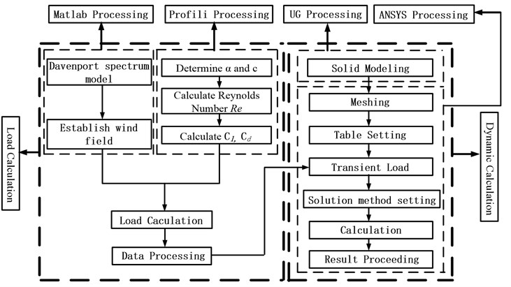
In the numerical simulation on the dynamical response of the blade, as described by above flowchart, the following calculation procedure is performed.
Step 1: Establish the theoretical model of Davenport wind spectrum, and build the wind field at different working conditions through simulation of random wind speed using Matlab.
Step 2: Obtain detailed data of wind turbine blade elements, such as chord length, attack angle, airfoil, and so on; create table files including attack angle in direction of blade wingspan and chord length .
Step 3: Calculate the Reynolds number for blade elements along the wingspan direction at different wind speeds by using Profili, and then find the lift coefficient and the drag coefficient for blade elements under the corresponding working conditions.
Step 4: Calculate the normal force and the tangential force of the blade by substituting the data obtained from above steps into Eqs. (4) and (5). Then, the solution of the blade aerodynamic load can be achieved.
Step 5: Establish the solid model of the blade using UG. Mesh the solid model and define constraints by using ANSYS.
Step 6: Load the aerodynamic forces obtained from Step 4 onto the stress surface of the blade, which has been meshed by employing table loading function in ANSYS. Set a reasonable load step and solve the deflection and the stress. Carry out the post-processing and analysis.
4.2. Reliability verification of simulation results
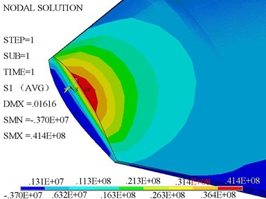
In order to verify the reliability of numerical results, the testing data in reference [17], where the wind turbine model is FD2-300 with a total power of 300 W, an airfoil of NACA632 series and a blade length of 0.85 meters, were compared with the data obtained from simulation method in this work. Aerodynamic tangential component, centrifugal force of rotating blade and blade weight were ignored in the test, and the aerodynamic force along blade wingspan direction was simplified into 7 concentrated forces distributed uniformly, as shown in Fig. 5. Combining geometric parameters with boundary conditions, the boot stress distribution of blade was found and is shown in Fig. 6. The maximum stress of the blade root under simulation is 41.4 MPa, which is very close to the test data value of 42.7 MPa with a relative error about 3.04 %. The result confirms the reliability of calculation program, the theoretical and numerical models used in this work.
Fig. 5Loading diagram of concentrated force on blade
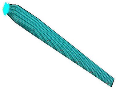
Fig. 6The maximum stress cloud picture of blade root
5. Results and discussion
The natural frequencies of the wind turbine blade are related to the vibration stability, and hence the blade natural frequencies are analyzed at first in order to study the influences of periodic wind speeds on blade dynamic responses. The calculated blade frequencies using ANSYS are listed in Table 1.
Table 1Blade natural frequencies under stationary state
Mode number | 1 | 2 | 3 | 4 | 5 | 6 |
Frequency (Hz) | 0.383 | 1.098 | 1.672 | 2.238 | 3.793 | 4.319 |
5.1. Vibration and stress analysis under periodic wind speeds
Fig. 7 shows the time spectrum of waving vibration of blade tip and middle part when the average speed of the complicated offshore wind is up to 20 m/s, which is close to the first natural frequency. It is evident from Fig. 7 that the waving vibrations diverge and the amplitudes increases gradually from the blade boot to the blade tip.
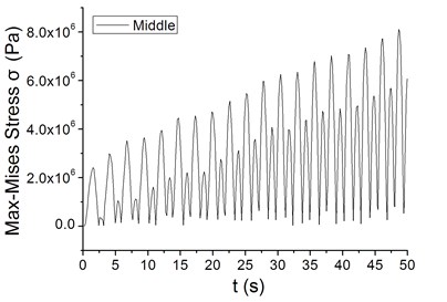
It was found from Fig. 7(b) and Fig. 8 that the maximum Mises stress increases with the increase of the waving amplitude, also showing divergence phenomena.
Fig. 7Waving vibration characteristics of different blade parts at periodic wind speed
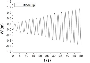
a) The tip part of blade
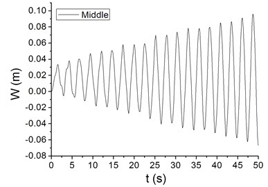
b) The middle part of blade
Fig. 8The divergence characteristics of the maximum Mises stress at periodic wind speed
5.2. Determination of critical curve
In applied wind farms, there are many kinds of wind speeds which may cause blade vibration to diverge. Therefore, it is very important to study variation laws of the amplitude and the stress at different wind speeds when the blade is unstable. The outcomes from the study can provide guidance for strength optimization design of the wind turbine blade.
Fig. 9Characteristic curves of maximum Mises stress and maximum waving amplitude vs. average wind speed with different elastic modulus
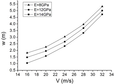
a) Maximum waving amplitude vs. average wind speed
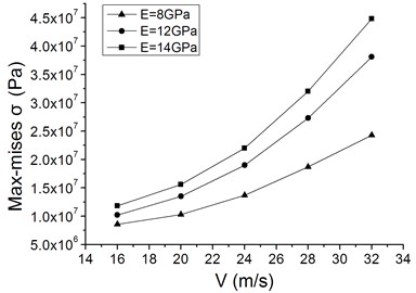
b) Maximum Mises stress vs. average wind speed
Fig. 9 gives the relationships among maximum Mises stress, maximum waving amplitude and average wind speed with different elastic modulus. Both the maximum Mises stress and the maximum waving amplitude of the blade increase nonlinearly with the average wind speed increasing. In addition, the maximum waving amplitude decreases and the maximum Mises stress increases, respectively, when elastic modulus is increased.
In view of the practical situation where the blade waving amplitude can not exceed the horizontal distance between the blade and the tower, the blade maximum waving amplitude is set at 1.5 meters according to a blade length of 40 meters, and it is then reduced to 1.0 meter for a safer design. This implies that the wind turbines cannot operate safely when the waving amplitude is more than above two set amplitudes. Under this condition, the quantitative relationship between maximum Mises stress and elastic modulus was studied.
Fig. 10Characteristic curves of the critical value of maximum Mises stress vs. elastic modulus with different horizontal distances
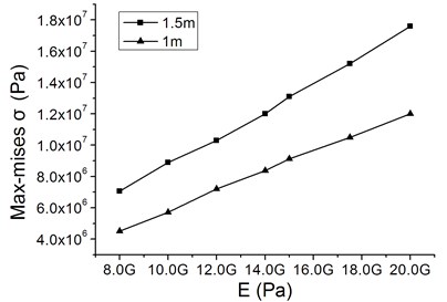
Fig. 10 plots the characteristic curves of the critical value of maximum Mises stress as a function of elastic modulus for different horizontal distances between the blade and the tower when the vibration diverges. Fig. 10 exhibits that the maximum Mises stress increases almost linearly with elastic modulus, and this linear trend does not vary with the horizontal distance. The dynamic stability region of blade safe operation is displayed in Fig. 10, which indicates that the elastic dynamic instability occurs when the maximum Mises stress at corresponding elastic modulus lies above the critical curve. Otherwise, the dynamic response of the blade is stable.
Although some progress has been made in dynamic stability analysis on wind turbine blade in this work, there exist some limitations to the present simulation as follows: 1) aerodynamic loads were calculated by using empirical formula, which cannot represent the real wind field completely; 2) the influences of fluid-structure coupling on the blade vibration were not taken into account.
6. Conclusions
In this study, blade dynamic stability caused average wind speed and elastic modulus was studied. The quantitative relationships among maximum waving amplitude, maximum Mises stress and wind speed under divergence of blade waving vibration were obtained under specific offshore wind conditions. Moreover, given of waving vibration divergence and the horizontal distance between blade and tower, the quantitative relationship between maximum Mises stress and elastic modulus was also found. The following conclusions can be drawn:
1) When the frequency of wind speed is close to the first natural frequency of the blade, the waving vibration diverges, and the maximum Mises stress and the maximum waving amplitude increase nonlinearly with the average wind speed respectively.
2) The dynamic stability regions of maximum Mises stress, elastic modulus and horizontal distance was obtained under periodic wind speed, and the blade operation is safe when the maximum Mises stress is in the regions below the critical curves.
3) Under the condition of various horizontal distances between blade and tower, the maximum Mises stress increases almost linearly with elastic modulus when the blade is unstable.
4) In a further research, the effects of blade rotation on dynamic stability should be considered with fluid-structure coupling included to simulate a more realistic working situation.
References
-
Joselin H. G. M., Iniyan S., Sreevalsan E., et al. A review of wind energy technologies. Renewable and Sustainable Energy Reviews, Vol. 11, Issue 1, 2007, p. 1117-1145.
-
Haruo S., Masahiro H. Reproduction of FRP blade failure for wind power generators by lighting and its mechanism. JSME International Journal, Vol. 48, Issue 4, 2005, p. 465-471.
-
Carnegie W., Dawson B. Vibration characteristics of straight blades of symmetrical aerofoil cross-section. The Aeronautical Quarterly, Vol. 178, 1963, p. 78-87.
-
Fadaeinedjad R., Moschopoulos G., Moallem M. Voltage sag impact on wind turbine tower vibration. Power Engineering Society General Meeting, 2007, p. 1-8.
-
Arrigan J., Pakrashi V., Basu B., et al. Semi-active frequency tracking algorithm for control of flapwise vibrations in wind turbine blades. Signals and Systems Conference, 2009, p. 1-6.
-
Sarim N. A preliminary study for designing wind turbine blades using Caribbean technology. Energy Conversion Engineering Conference and Exhibit, (IECEC) 35th Intersociety, 2000, p. 767-774.
-
Driss Z., Karray S., Damak A., et al. Effect of the Reynolds number on the aerodynamic characteristics of a horizontal axis wind turbine. First International Conference on Renewable Energies and Vehicular Technology (REVET), 2012, p. 317-323.
-
Yang C., Lv X., Tong G., et al. Aerodynamic optimization design and calculation of a 2 MW horizontal axial wind turbine rotor based on blade theory and particle swarm optimization. Power and Energy Engineering Conference (APPEEC), Asia-Pacific, 2011, p. 1-4.
-
Darris L. W., Walt D. M. The effect of load phase angle on wind turbine blade fatigue damage. Transactions of the ASME, Vol. 126, 2004, p. 1050-1060.
-
Wang J., Huang Z., Li Y. Computation method on fatigue life of a full composite wind turbine blade. Power and Energy Engineering Conference (APPEEC), Asia-Pacific, 2010, p. 1-4.
-
Pan L. Analysis on Dynamic Response of the Offshore Wind Turbine Blade. Master Degree Thesis, Shanghai: Shanghai University of Electric Power, 2009.
-
Wang X., Cui J. Formula of coefficient K in expression of Davenport spectrum and its engineering application. Journal of Tongji University, Vol. 30, Issue 7, 2002, p. 849-852.
-
He D. Wind Engineering and Industrial Aerodynamics. Beijing: National Defence Industry Press, Vol. 79, 2006.
-
Newmark N. M. A method of computation for structural dynamics. Journal of the Engineering Mechanics Division, ASCE, Vol. 85, 1959, p. 67-94.
-
Zhang J., Li Z. Dynamic instability of magnetoelastic coupling interactions of cantilever conductive thin plates. Journal of Zhejiang University (Engineering Science), Vol. 40, Issue 3, 2006, p. 414-418.
-
Cheng Z., Yang C., Li R. A numerical method in aerodynamic computation for wind turbine rotor. Mechanics in Engineering, Vol. 29, Issue 6, 2007, p. 44-47.
-
Cao R., Liu D. Experimental investigation on static structural characteristics of a horizontal axis wind turbine. Acta Energiae Solaris Sinica, Vol. 22, Issue 4, 2001, p. 436-439.
About this article

This study was financially sponsored by various research funds including the Program of Shanghai Subject Chief Scientist (B type) (13XD1425200); Shanghai Committee of Science and Technology, China (11160500600, 11dz2281700, 09DJ1400204); Innovation Program of Shanghai Municipal Education Commission (11ZZ171, 13ZZ130); Shuguang Project of Shanghai Municipal Education Commission (09SG51); Key Discipline of Shanghai Education Commission (J51304); National Natural Science Foundation of China (50706025, 51201097); the “085 Program” Project Foundation of Shanghai University of Electric Power.
