Abstract
In this paper, the minimality of the quadratic sum of the reflected sound pressure is used to outline the method of active sound absorption. A piezoelectric ceramic is attached to a simply supported plate, and two microphones are placed in the front of the simply supported plate. The reflected sound pressure is measured. According to the measured reflected sound pressure, the voltage is added to the surface of the piezoelectric ceramic. Then, the simply supported plate is vibrated. Thus, the total sound pressure is expressed as a combination of the reflected sound pressure and the radiated sound pressure. A condition of the quadratic sum being minimal is presented and the voltage (added to the surface of the piezoelectric ceramic) is calculated. At last, the numerical calculation and the experiment are carried out, which demonstrate that the method outlined in this paper is possible.
1. Introduction
In 1960s, active sound elimination raised a great interest amongst scholars. Active sound elimination is a method that uses primary sound source sound waves in order to produce equal and opposite in phase waves from a secondary sound source (destructive interference between the two sources results in sound elimination).
The expected control goals are achieved and the purpose of the elimination is attained. The method was proposed by Paul Lueg, who patented it in 1934 and explained its basic theory in 1936 [1-3]. The electronic control system could not be manufactured due to electronic technology imitations. Therefore, the technology had not been developed until the late 1960s. With the development of electronic technology, scholars posed the method of sound elumination again. The present study hotspot is using structural acoustic radiation to offset the incidental acoustic energy in order improve the absorption effect. There have been a lot of reseach achievements and some research results have been used in practice.
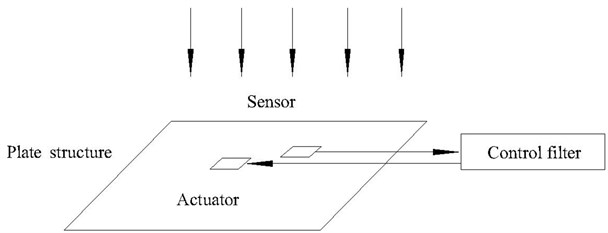
The basic principle of the elimination is shown in Fig. 1, when the sound wave is incident to the flat plate. The sound signal is detected by the sensor placed in front of the plate. The detected sound signal is transmitted to the control filters, which give the controlled signal to the actuator attached to the plate (the plate is assumed to be elastic). When the elastic plate has no secondary force source effect, the acoustic field above the plate includes: incidental sound pressure , the reflected sound pressure by the elastic plate and the acoustic radiation pressure . These elements form the following formula [4-6].
Fig. 1Active noise elimination is using a plate structure
When the secondary force source effects the elastic plate, the radiated sound pressure is . So the total sound pressure is:
Similarly, when the elastic plate has no secondary force source, the velocity in the space above the elastic plate includes three parts: (1) he velocity generated by the incident sound wave; (2) the reflected velocity generated by the elastic plate; (3) the radiated velocity , which is shown as the following formula:
When the secondary force source effects the elastic plate, the radiated velocity is generated and the total velocity is shown as the following formula:
Therefore, when the secondary force source effects on the elastic plate, the overall sound power of the elastic plate is:
In order to achieve the purpose of the activity eliminated, the overall sound power should be minimal and the control target is:
The incident sound pressure is constant, which has no affection on the derivation. the minimality of the quadratic sum of the reflected sound pressure is used to outline the method of active sound absorption. A piezoelectric ceramic is attached to a simply supported plate, and two microphones are placed in the front of the simply supported plate. The reflected sound pressure is measured. According to the measured reflected sound pressure, the voltage is added to the surface of the piezoelectric ceramic. Then, the simply supported plate is vibrated. Thus, the total sound pressure is expressed as a combination of the reflected sound pressure and the radiated sound pressure. A condition of the quadratic sum being minimal is presented and the voltage (added to the surface of the piezoelectric ceramic) is calculated.
2. The theory calculation method of the quadratic sum of the reflected sound pressure with monolithic piezoelectric ceramic chips
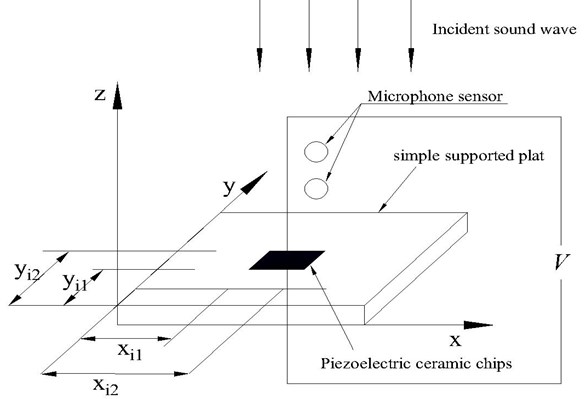
The arrangement of the monolithic piezoelectric ceramic chip is shown in the Fig. 2.
Fig. 2Active sound absorption is based on the minimality of quadratic sum of the reflected sound pressure
For the external voltage , the strain of the th piezoelectric ceramic chips is:
where is the thickness of the th piezoelectric ceramic chip and is the strain constant of the piezoelectric ceramic chip. In the Fig. 2, the piezoelectric ceramic chips are attached to the simply supported plate and the double direction longitudinal force reads [7-15]:
According to the formula (8), the motion equation of the simply-supported plate is:
For the formula (10), the displacement of the simply-supported plate at any location and time can be expressed using the vibration modal method:
where is modal amplitude caused by the piece of piezoelectric ceramic chip and is the vibration modal shape function of the position :
Putting the formula (11) and (12) into the formula (10) and then multiplying on both sides of formula (10) yields:
When the model is mutually orthogonal, the integral of any two different vibration models along the surface of simply supported plate is equal to zero. Therefore, the equation (13) reads:
According to the formula (14), the inherent frequency is:
is multiplied by the right of formula (9) and yields:
According to the formula (16), the following formula yields:
To make formula (14) and formula (17) equal, the modal amplitude is expressed as:
According to the above formula, the vibration displacement of the simply supported plate can be yield (which is differential). The vibration velocity of the simply supported plate’s surface is:
where is the number of piezoelectric ceramic chips that are attached to the simply supported plate. According to the above analysis and the calculation method, the sound pressure is expressed as matrix:
The radiated sound pressure of the simply supported plate caused by piezoelectric ceramic chip is:
The simple supported plate is divided into units as showed in the Fig. 3.
Fig. 3Element division of the supported plate
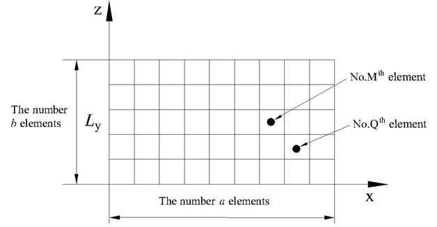
According to the Fig. 3, the center coordinations of the No. thelement and the No. thelement are:
where and are the orders directing and yof the No. Mth rectangular element in the Fig. 3. and is the order directing and y of the No. th rectangular element. Due to the elements being tiny, the coordinate of the No. th rectangular element is and the coordinate of the No. Qth rectangular element is . The distance between the No. Mth rectangular element and No. Qth rectangular element is:
Due to the elements being tiny, the surface vibration velocity of every element is equal, thus the velocity of the No. th rectangular element is:
Accordingly, formula (23) and formula (24) are put into the formula (23):
where is the density of the air, is the area of each element, . The formula (25) can be denoted as the following formula:
According to the above mentioned, when there are no secondary force effects on the simple supported plate, the reflected sound consists of two parts: (1) geometric reflected waves (in the condition that the elastic is rigid plate) and (2) the acoustic radiation wave :
When the piezoelectric ceramic chip attached to the simply supported plate has voltage, the radiation sound pressure is . The total reflected sound pressure is:
Assuming the incident sound wave doesn't work, (the incident sound pressure is zero) the formula (28) is:
The incident sound wave is a plane wave, therefore the reflected sound pressure can be shown as the following formula:
Put the formula (26) and the formula (30) into the formula (29):
According to the formula (31), the standards of the method mentioned in this paper are attained. The corresponding target function is:
is the function of the voltage and the angular frequency of the piezoelectric ceramic chip. If the value of the formula (32) is minimum, the following formula is:
The calculated voltage and frequency (according to the above formula) is the voltage and frequency of the piezoelectric ceramic chip.
3. Measurement theory of the incident and reflection wave
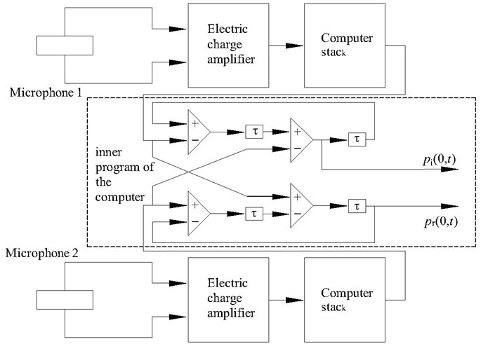
If the wave is a plane sound wave, the incidence and reflection sound waves can be expressed as:
where is the wave number and is the frequency of the sound wave.
The signals of microphone 1 and microphone 2 are:
where is the propagation time between microphone 1 and microphone 2, . is the propagation velocity of the wave in the air. If the sound pressure is delayed by , then the following equation yields:
Signal is defined as:
If the signal is delayed by , then the signal is:
If the signal is delayed by , then the following equation yields:
Signal is defined as:
According to the Eq. 41 and Eq. 42, the following equation can be attained:
The signal is the reflective sound pressure of microphone 1. The reflective sound pressure in the place of the front piezoelectric ceramic is:
The principle of measuring the incidence and reflection sound pressure by two microphones is shown in Fig. 4.
Fig. 4The principle of measuring the incidence and reflection sound pressure
4. Numerical calculation and experiment
The experimental diagram is shown as the Fig. 5.
The rectangular tube for the experiment is 400 mm×400 mm×3000 mm. The primary source is a speaker, which is located at the end of the tube. The distance between the two microphone sensors is 5 cm and the distance between microphone 2 and the simply supported plate is 2.5 cm. The density of the air is . The propagation velocity in the air is The density of the simply supported plate is ; the thickness is ; elastic modulus is the Poisson’s ratio is The thickness of piezoelectric ceramic chip is the piezoelectric constant of the piezoelectric composites is ; elastic modulus is ; Poisson’s ratio is .
Fig. 5The experiment arrangement
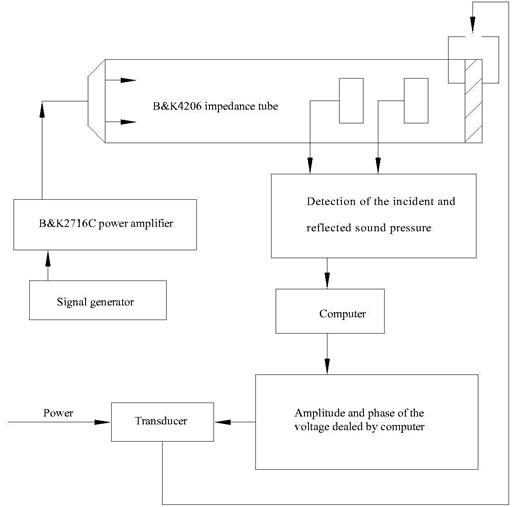
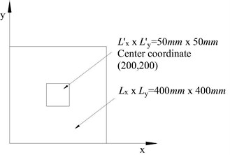
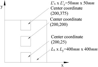
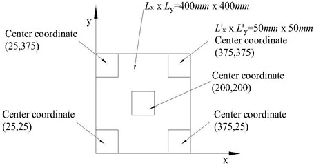
Fig. 6Layout diagram of piezoelectric ceramic chip
a)
b)
c)
In this experiment, piezoelectric ceramic chips are divided into: single chip piezoelectric ceramic chips; three piezoelectric ceramic chips; five piezoelectric ceramic chips. Fig. 6 is the various layout diagram.
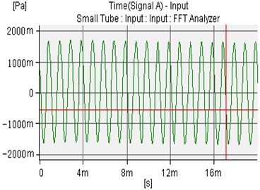
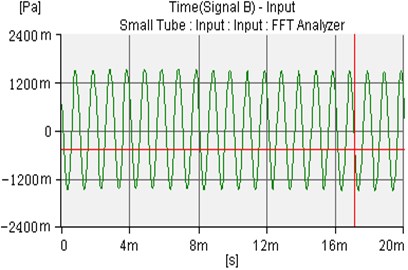
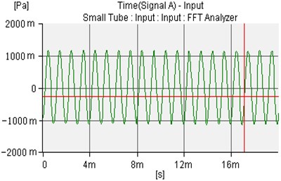
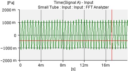
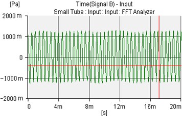
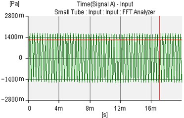
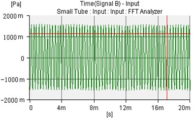
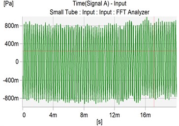
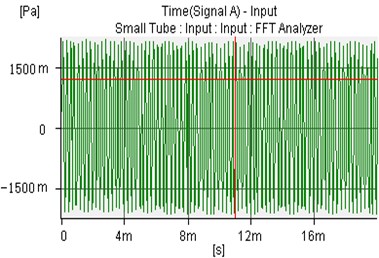
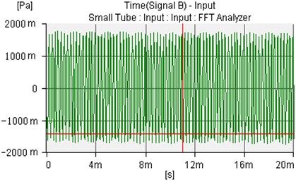
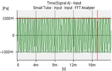
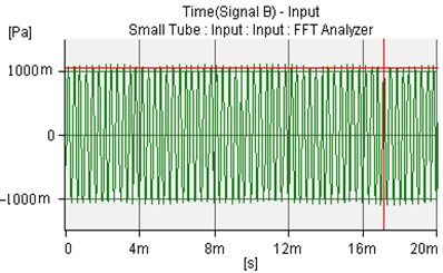
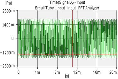
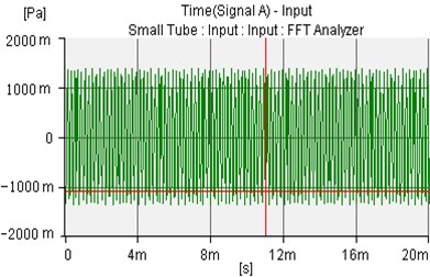
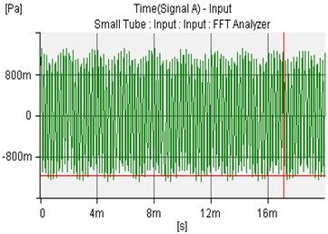
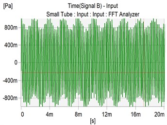
The sound wave pressure figure is following one piece of the piezoelectric ceramic chip. In order to simplify, in this experiment, the incident sound wave is a sine wave. The amplitude is 1.0 Pa and the frequency is 1000 Hz. The incident sound wave and the uncontrolled sound waves of microphone 1 and microphone 2 are shown in Fig. 7-9.
Fig. 7The incident sound wave of amplitude is 1.0 Pa and frequency is 1000 Hz
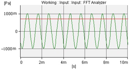
Fig. 8The uncontrolled sound waves of microphone 1 and microphone 2
a)
b)
Fig. 9The controlled sound waves of microphone 1 and microphone 2
a)
b)
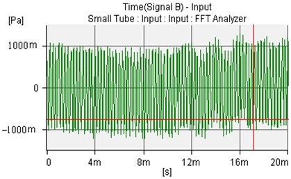
The amplitude is 1.0 Pa and the frequency is 2000 Hz. The incident sound wave, the uncontrolled sound waves of microphone 1 and microphone 2 are shown in Fig. 10-12.
Fig. 10The incident sound wave of amplitude is 1.0 Pa and frequency is 2000 Hz
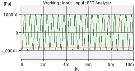
Fig. 11The uncontrolled sound wave of microphone 1 and microphone 2
a)
b)
Fig. 12The controlled sound wave of microphone 1 and microphone 2
a)
b)
The amplitude is 1.0 Pa and the frequency is 3000 Hz, The incident sound wave, uncontrolled sound wave of microphone 1 and microphone 2 are shown as Fig. 13-15.
Fig. 13The incident sound wave of amplitude is 1.0 Pa and frequency is 3000 Hz
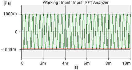
Fig. 14The uncontrolled sound wave of microphone 1 and microphone 2
a)
b)
Fig. 15The controlled sound wave of microphone 1 and microphone 2
a)
b)
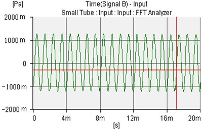
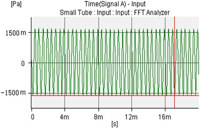
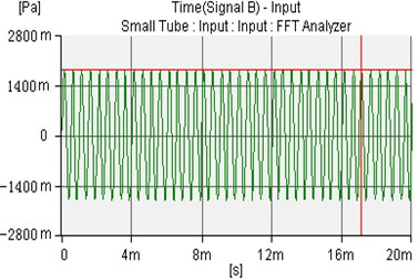
The amplitude is 1.0 Pa and the frequency is 4000 Hz. The incident sound wave, uncontrolled sound waves of microphone 1 and microphone 2 are shown in Fig. 16-18.
Fig. 16The incident sound wave of amplitude is 1.0 Pa and frequency is 4000 Hz
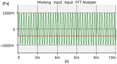
Fig. 17The uncontrolled sound wave of microphone 1 and microphone 2
a)
b)
Fig. 18The controlled sound wave of microphone 1 and microphone 2
a)
b)
The amplitude is 1.0 Pa and the frequency is 5000 Hz. The incident sound wave, uncontrolled sound waves of microphone 1 and microphone 2 are shown in Fig. 19-21
Fig. 19The incident sound wave of amplitude is 1.0 Pa and frequency is 5000 Hz
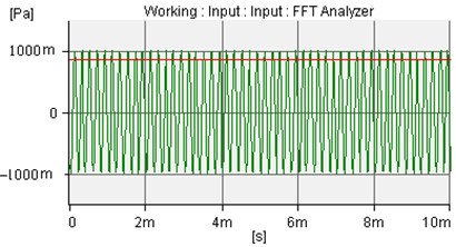
Fig. 20The uncontrolled sound wave of microphone 1 and microphone 2
a)
b)
Fig. 21The controlled sound wave of microphone 1 and microphone 2
a)
b)
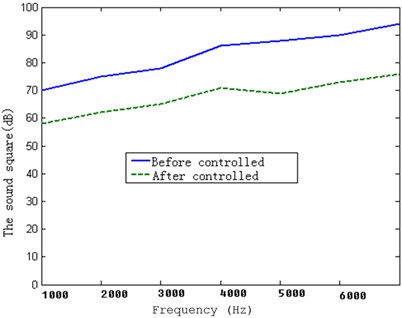
For one piece of the piezoelectric ceramic chip, the sqaure sums of sound before controlling (voltage not applied) and after controlling (voltage applied) are shown in the Fig. 22.
Fig. 22The sound pressure squares of a piezoelectric ceramic chip before and after controlling
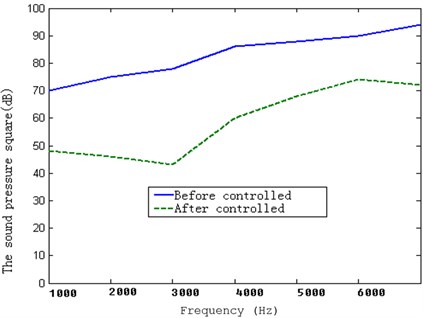
For three pieces of the piezoelectric ceramic chips, the sqaure sums of sound before controlling (voltage not applied) and after controlling (voltage applied) are shown in the Fig. 23.
Fig. 23The sound pressure squares of three piezoelectric ceramic chips before and after controlling
For five pieces of the piezoelectric ceramic chips, the sqaure sums of sound before controlling (voltage not applied) and after controlling (voltage applied) are shown in the Fig. 24.
Fig. 24The sound pressure squares of five piezoelectric ceramic chips before and after controlling
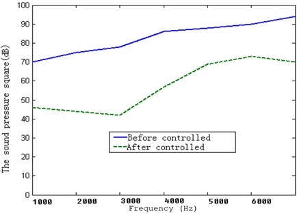
From Fig. 7 to Fig. 24, the experimental results obtained the absorption effect. And yet the absorption effect is different from the amount of the piezoelectric ceramic chips. When the amount of piezoelectric ceramic chips is three pieces, the sound absorption effect is superb. If the amount is increased, the absorption is not obvious.
5. Conclusions
Active sound elimination raised a great interest amongst the scholars. Active sound elimination is a method that uses primary sound source sound waves in order to produce equal and opposite in phase waves from a secondary sound source (destructive interference between the two sources results in sound elimination). The expected control goals are achieved and the purpose of the elimination is attained. This effect is unsatisfactory, so this paper puts forward an absorption method based on the minimalism of the reflections power. The minimality of quadratic sum of the reflected sound pressure is used to outline the method of active sound absorption. A piezoelectric ceramic is attached to a simply supported plate, and two microphones are placed in the front of the simply supported plate. The reflected sound pressure is measured. According to the measured reflected sound pressure, the voltage is added to the surface of the piezoelectric ceramic. Then, the simply supported plate is vibrated. Thus, the total sound pressure is expressed as a combination of the reflected sound pressure and the radiated sound pressure. A condition of the quadratic sum being minimal is presented and the voltage (added to the surface of the piezoelectric ceramic) is calculated. In this paper, all measured signals are harmonic. In order to conveniently calculate the equations and finish the experiment, the excited force is a harmonic sound wave. Since the excited force is harmonic sound wave, the microphones signals are harmonic. According to the related equations, the sound signals can be transformed to the sound pressure signals and then sound pressure squares can be calculated. Of course, if the excited force is random, the equation and the conclusion are correct too.
References
-
Kenneth A. Cunefare, Gary H. Koopmann. Global optimum active noise control: Surface and far field effects. Journal of the Acoustical Society of America, Vol. 90, Issue 1, 1991, p. 365-373.
-
Kenneth A. Cunefare, Gary. H. Koopmann. Acoustic design sensitivity for structural radiators. ASME Journal of Vibration and Acoustics, Vol. 114, Issue 2, 1992, p. 178-186.
-
Kenneth A. Cunefare. The effect of modal interaction on sound radiation from vibrating structures. AIAA Journal, Vol. 30, Issue 12, 1992, p. 2819-2828.
-
Borgiotti G. V. The power radiated by a vibrating body in an acoustic fluid and its determination from boundary measurements. Journal of the Acoustical Society of America, Vol. 88, Issue 4, 1990, p. 1884-1893.
-
Photiais D. M. The relationships of singular value decomposition to wave-vector by three-dimensional structures. Journal of the Acoustical Society of America, Vol. 88, Issue 4,1990, p. 1152-1159.
-
Cunfeare K. A. On the exterior acoustic radiation modes of structure. Journal of the Acoustical Society of America, Vol. 96, Issue 4, 1994, p. 2302-2312.
-
Curnfare K. A. The radiation modes of baffled finite plates. Journal of the Acoustical Society of America, Vol. 98, Issue 3, 1995, p. 1570-1580.
-
Elliott S. J. Radiation modes and the active control of sound power. Journal of the Acoustical Society of America, Vol. 94, Issue 4, 1993, p. 2194-2204.
-
D. Guicking, K. Karcher. Active impedance control for one-dimensional sound. Journal Vibration Acoustic Stress Reliability, Vol. 106, Issue 1, 1984, p. 393-396.
-
D. Guicking, E. Lorenz. An Active sound absorber with porous plate. Journal Vibration Acoustic Stress Reliability, Vol. 106, Issue 2, 1984, p. 389-392.
-
Guicking D., Karcher K., Roll wage M. Active control of the acoustic reflection coefficient at low frequencies. In Proceeding of Inter-Noise’83, 1983, p. 419-422.
-
Guicking D., Albrecht M. An electric loudspeaker for active acoustic systems. Journal of vibration, Acoustics, Stress, and Reliability in design, Vol. 106, Issue 1, 1984, p. 397-398.
-
C. R. Fuller, M. J. Bronzel, C. H. Gentry, D. E. Whittington. Control of sound radiation/reflection with adaptive foams. In Proceedings of Noise-Con 1994 Fort Lauderdale, Florida.
-
Thenail D., Lacour O., Galland M. A., Furtoss M. The active control of wall impedance. Acoustic, Vol. 83, Issue 1, 1983, p. 1039-1044.
-
M. Furstoss, D. Thenail, M. A. Galland. Surface impedance control for sound absorption: Direct and hybrid passive/active strategies. Journal of sound and vibration, Vol. 203, Issue 2, 1997, p. 219-236.
About this article

