Abstract
A semi-active suspension design based on the traditional method of skyhook control is not capable of effectively controlling the attitude of the vehicle. However, an innovative approach called decoupling skyhook control allows the attitude of the vehicle body and its vibration characteristics to be effectively controlled. In this paper, a new decoupling skyhook controller for semi-active suspension is presented. Vehicle body motions in the three directions of vertical, pitch, and roll have been adopted to develop three skyhook controllers and directly control the vehicle body attitude. Furthermore, three orientation skyhook control forces are converted into actual damping forces of four adjustable dampers through the input decoupling transformation. The simulation results show that the developed controller is more effective than the traditional skyhook control in improving ride comfort.
1. Introduction
Since the skyhook control scheme was introduced in the early 1970s by D. Karnopp, this method has been used in many vibration isolation applications [1]. In active and semi-active suspension control, the skyhook control scheme is an extremely effective control strategy and has been used in some commercial applications. Moreover, the skyhook scheme is often used as the reference model for other control strategies because of its simplicity and its prominent effect in improving ride comfort [2-4].
To develop the semi-active control algorithm for a full-vehicle system, two different methodologies can be used [5]. One methodology uses the quarter car model to develop the control algorithm, which is then implemented in a full vehicle model for controlling and analysis [6-8]. However, this methodology does not directly consider the pitch and roll motions of the vehicle. Furthermore, four accelerometers on the four corner points of the sprung mass are usually used to design controllers. As the aim of the suspension is to control the acceleration felt by the passengers, this acceleration should be considered at the vehicle’s center of gravity and not over the wheels. Thus, the control of the body posture may be inadequate.
Another methodology uses a full-vehicle model to directly control both the vertical motion (heave) and the angular motion (pitch and roll) of the vehicle body [9, 10]. The advantage of this methodology is that a control strategy can be designed that effectively controls the attitude of the sprung mass and suppresses the vibration of the suspension. In [9], three fuzzy controllers are designed to produce three forces , and to suppress the heave, pitch, and roll movements. The input variables for the controllers are velocities and accelerations in three orientations. Then, the three forces are decoupled into four forces generated by active force generators. A double-loop control scheme is presented to control the active suspension in [10]. The inner control loop adopts the active filtering of the spring and damping coefficient to design the ride controller, while the outer control loop maintains load-leveling and load distribution during vehicle maneuvers using skyhook scheme. Finally, three forces, which control the heave, pitch, and roll movements, are also decoupled into the four active generators’ forces. Reference [11] also proposes a decoupled quarter car active suspension model that introduces a new abstract variable denoted by . For semi-active suspension, a coupling design using skyhook damping is mentioned in [12]. However, no further explanation is given. According to the theory of skyhook damping forces that damp heave and angular motion proposed in [1], this study develops semi-active suspension controllers through a direct use of the skyhook damping. First, three ideal skyhook controllers are designed to command forces that damp the vehicle body’s heave, pitch, and roll motions. Next, the three orientation forces are decoupled into damping forces of four adjustable dampers, which are constrained by passivity. The developed strategy is simple and effective.
2. Full vehicle model
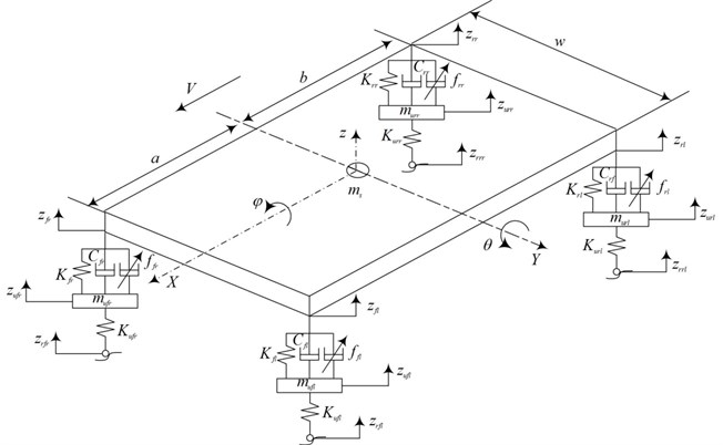
The vehicle is represented as a linearized seven-degree-of-freedom system, as shown in Fig. 1. This model is similar to the model used in [13]. It consists of a sprung mass (car body) and four unsprung masses. For simplicity, all pitch and roll angles are assumed to be small. The suspension is also modeled as linear spring and damper, while the tires are modeled as simple linear springs without damping. The damper is divided into two parts: the damper with a fixed damping coefficient and the damper with a variable damping coefficient.
Newton’s second law applied to the system results in the following differential equations of motion:
The kinematic equations representing the displacement at each corner are given as follows:
where: – heave displacement of the vehicle body’s mass center, – pitch/roll angle, , , , – heave displacement of the vehicle body at the suspension locations, , , , – heave displacement of the unsprung mass, , , , – excitation from the road surface, , , , – variable damping force, and – the acceleration due to gravity.
Fig. 1Vehicle model with seven degrees of freedom
The full-vehicle mode parameters were adopted from [8] and are summarized in Table 1.
Table 1Model parameters
Symbol | Description | Units |
Sprung mass | 1465 kg | |
Unsprung mass | 40 kg | |
Front suspension stiffness | 19960 N/m | |
Rear suspension stiffness | 17500 N/m | |
Tire stiffness | 175500 N/m | |
Fixed damping of the front dampers | 258 N/m/s | |
Fixed damping of the rear dampers | 324 N/m/s | |
Pitch moment of inertia | 2460 kg/m2 | |
Roll moment of inertia | 460 kg/m2 | |
Longitudinal distance from vehicle c.g. to front axle | 1.4 m | |
Longitudinal distance from vehicle c.g. to rear axle | 1.7 m | |
Track width | 3 m |
3. Input decoupling transformation
The actuators used to implement the semi-active suspension are continuously adjustable dampers (such as MR dampers), which are installed in all four corners of the vehicle. Each damper is independently controlled to improve the vehicle ride. The sprung mass acceleration at the body’s center of gravity should be considered rather than that over the wheels, because the suspension control target is to reduce the acceleration in the location of the occupants. Thus, the damping force of four dampers should be associated with the control forces for three sprung mass accelerations. In this project, the vehicle body posture is directly controlled, considering the heave, pitch, and roll motions, and the three sprung mass accelerations (, and ) at the center of gravity are also controlled.
From Eq. (1), the equivalent forces for heave, pitch, and roll can be defined by:
and expressed in a matrix form:
Eq. (4) takes the form ‘’, where is the vector, is the vector, and is the matrix. The pseudo right inverse can be obtained using , . Thus, Eq. (4) can be expressed as:
By entering the decoupling transformation expressed by (5), the control for heave, pitch, and roll of the car body is converted into the control for the four dampers.
4. Skyhook control design
In a full-vehicle suspension system, the rigid body of the vehicle (i.e., the sprung mass) has three DOFs of heave, pitch, and roll, as HPR in the rest of this paper.
According to the theory of skyhook damping presented in [1], the ideal skyhook control forces in three orientations (i.e., heave, pitch, and roll) for the suspension system of a full car model can be expressed as:
where is the skyhook control gain, consists of the HPR velocities of the vehicle body, and , and represent the heave, pitch, and roll orientations, respectively.
We obtain an over-actuated system with three degrees of freedom controlled by four actuators. Thus, the three ideal skyhook control forces must be decoupled. Meanwhile, the actual adjustable dampers cannot produce active forces, so the semi-active suspension controller can only be conducted in an on-off control. Thus, the actual skyhook controller needs the velocities and relative suspension velocities of the sprung mass. Given the problem of measuring relative velocity in a practical application, velocities of sprung mass and relative velocities at each suspension corner are adopted to build a skyhook controller to achieve a direct input decoupling. In this decoupling skyhook control, seven sensors are needed: three sprung mass accelerometers (measuring and ) and four displacement sensors (measuring suspension relative displacement).
The semi-active skyhook control forces that are constrained by passivity can be expressed as:
where , , , and , and .
consists of the HPR velocities of the vehicle body, and of the relative velocities at each suspension corner.
From Eq. (2), the HPR velocities of the four corner points of the vehicle body can be obtained:
Finally, the actual control force demanded from each damper can be calculated by Eqs. (5) and (7).
5. Simulation
The simulation focuses on the vehicle ride comfort and is representative of the vehicle body accelerations. To validate the decoupling skyhook control (DSKY) scheme proposed in this study, a passive suspension is also simulated with fixed damping forces acting on the four dampers. The passive suspension is treated as the baseline for DSKY control. Furthermore, a traditional skyhook control (TSKY) for a full-vehicle system is simulated too. It is controlled from its four corners according to the skyhook control scheme for the quarter-car model. This controller uses eight sensors (i.e., four acceleration and four deflection sensors). For simplicity, the MRDs are considered as ideal linear adjustable dampers, although a polynomial model has been proposed in our previous research [14].
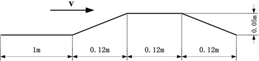
The suspension system in this study has been simulated for two cases, in which a delay is introduced between the front and rear axles. In the first case, the periodic road inputs have three different values of frequency, that is, 8 rad/s, 69 rad/s, and 140 rad/s. The input terrain disturbances have been defined as sinusoids given by, , , where is the terrain disturbance frequency and , , and are the terrain disturbance amplitudes at the front-left, front-right, rear-left, and rear-right wheels, respectively. The time delay is given by and the speed at which the vehicle travels is given by . The vehicle is driving along a straight longitudinal trajectory at a constant speed . Hence, longitudinal and lateral dynamics do not interfere with the vertical dynamics. Other simulation parameter values are selected as , . In the second case, the road disturbance is the “speed bump” used in [15], the profile and dimension of which are shown in Fig. 2. Only the left side of the vehicle meets a bump, so that both pitch and roll motion are produced at the same time. Moreover, the skyhook gains for heave, pitch, and roll are 2000 N/m/s, 3000 N/m/s, and 3000 N/m/s, respectively.
Fig. 2‘Speed bump’ profile
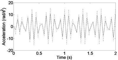
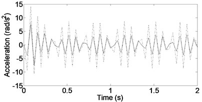
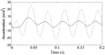
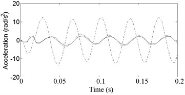
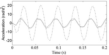
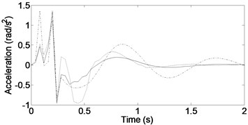
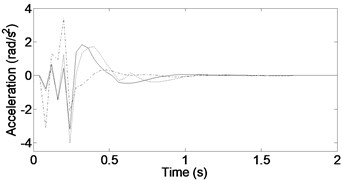
Figs. 3-5 show the heave, pitch, and roll accelerations at low and high frequencies when the vehicle is given periodic road inputs. As can be seen, responses from low to high frequencies are considerably better for the new configuration compared with those from the traditional skyhook and passive cases.
Figure 6 shows the vehicle acceleration response for a speed bump. The vertical acceleration is shown in Fig. 6(a). The DSKY configuration clearly yields the best results. The reduction of peak acceleration is approximately 20 % more than that in the passive case and 10 % more than that in the traditional skyhook case. Both the DSKY and TSKY configurations attenuate the vertical motions faster than the passive configuration does. The pitch response is shown in Fig. 6(b). As can be seen, the DSKY configuration yields the smallest peak and the fastest time in eliminating the pitch motions. Fig. 6(c) shows the roll response. As can be seen, the DSKY configuration also yields the smallest peak. However, the passive configuration converges faster than do the DSKY and TSKY cases.
Fig. 3Vehicle acceleration responses for input frequency ω= 8 rad/s. ––––––– DSKY, - - - - - TSKY, -∙-∙-∙-∙- Passive
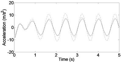
a) Heave acceleration
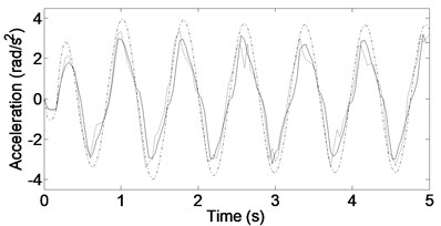
b) Pitch acceleration
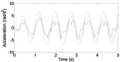
c) Roll acceleration
Fig. 4Vehicle acceleration responses for input frequency ω= 69 rad/s. ––––––– DSKY, - - - - - TSKY, -∙-∙-∙-∙- Passive
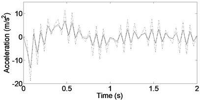
a) Heave acceleration
b) Pitch acceleration
c) Roll acceleration
Fig. 5Vehicle acceleration responses for input frequency ω= 140 rad/s. ––––––– DSKY, - - - - - TSKY, -∙-∙-∙-∙- Passive
a) Heave acceleration
b) Pitch acceleration
c) Roll acceleration
Fig. 6Vehicle acceleration responses for ‘speed bump’ road exciting. ––––––– DSKY, - - - - - TSKY, -∙-∙-∙-∙- Passive
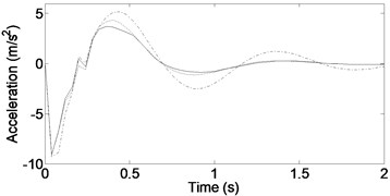
a) Heave acceleration
b) Pitch acceleration
c) Roll acceleration
6. Conclusions
A semi-active suspension using a novel methodology called DSKY was developed to control the attitude of the vehicle body and to suppress the vibration of the suspension. In accordance with the vehicle body motion (vertical, pitch, and roll), three skyhook controllers were designed. An input decoupling transformation converted the three orientation skyhook control forces into actual damping forces of four adjustable dampers. The simulations were conducted under two kinds of road inputs: periodic road inputs with three different frequencies and a “speed bump” input. The results showed that the proposed semi-active system provides better ride control in the heave, pitch, and roll motions of the vehicle body compare with the traditional semi-active and passive systems.
The time delay of system is an important issue that needs careful treatment to avoid poor performance or even possible instability of the control closed-loop system. For semi-active full-vehicle model systems, unavoidable time delays may appear in the controlled channel, in sensors, and in MRD where the delays are taken by the dampers to build up the required control force. Although this paper doesn’t consider time delay, it doesn’t affect the effectiveness of the proposed methodology and the simulation results. Usually, the stability and performance of the system due to a retarded control force have been studied only after the controller was designed [16]. The time delay of system will be considered before an experiment study in future research.
References
-
Karnopp D., Crosby M. J., Harwood R. A. Vibration control using semi-active force generators. J. of Engineering for Industry, 1974, p. 619-626.
-
Narges Maleki, Ali Khaki Sedigh, Batool Labibi Robust model reference adaptive control of active suspension system. Proceedings of the Control and Automation-MED, 14th Mediterranean Conference, 2006, p. 1-6.
-
Ardeshir Karami Mohammadi Vehicle active suspension control, using a variable structure model reference adaptive controller. Proceedings of the ACSE 05 Conference, CICC, Cairo, Egypt, 2005, p. 616.
-
Parthasarathy S., Srinivasa Y. G. Design of an active suspension system for a quarter-car road vehicle model using model reference control. J. Systems and Control Engineering, Vol. 220, p. 91-108.
-
Zifan Fang, Wenhui Shu, Daojia Du, et al. Semi-active suspension of a full-vehicle model based on double-loop control. Procedia Engineering, Vol. 16, 2011, p. 428-473.
-
Sedeh R. S., Ahmadian M. T., Abdollahpour R., et al. Application of car semi-active suspension systems to achieve desired performance on decreasing effect of road excitation on human health. Proceedings of the ASME International Design Engineering Technical Conferences and Computers and Information in Engineering Conference, Vol. 6, 2005, p. 375-382.
-
Yagiz N., Sakman L. E. Fuzzy logic control of a full vehicle without suspension gap degeneration. International Journal of Vehicle Design, Vol. 42, Issue 1-2, 2006.
-
Emmanuel D. Blanchard On the control aspects of semiactive suspensions for automobile applications. Master Dissertation, Blacksburg, Virginia, USA, Virginia Polytechnic Institute and State University, 2003.
-
Laoufi M., Eskandarian A. Fuzzy logic control for active suspension of a non-linear full-vehicle model. IEEE Intelligent Vehicles Symposium Proceedings, 2009, p. 677-684.
-
Ikenaga S., Lewis F. L., Campos J., et al. Active suspension control of ground vehicle based on a full-vehicle model. Proceedings of the American Control Conference, Vol. 6, 2000, p. 4019-4024.
-
Lakehal-Ayat M., Diop S., Fenaux E. Development of a full active suspension system. Proceedings of the IFAC World Congress, Barcelona, Spain, 2002, p. 2658.
-
Xubin Song Cost-effective skyhook control for semiactive vehicle suspension applications. The Open Mechanical Engineering Journal, Vol. 3, 2009, p. 17-25.
-
Chalasani R. M. Ride performance potential of active suspension system – part 2: comprehensive analysis based on a full-car model. Symposium on Simulation and Control of Ground Vehicles and Transportation Systems, Anaheim CA, ASME AMD-Vol. 80, DSC-Vol. 2, 1986, p. 205-234.
-
Yao Jialing, Zheng Jiaqiang, Gao Weijie, Zhang Zhenjun Sliding mode control of vehicle semi-active suspension with magnetorheological dampers having polynomial model. Journal of System Simulation, Vol. 21, Issue 8, 2009, p. 2400-2404, (in Chinese).
-
Dong Xiaomin Human simulated intelligent control of automobile magnetorheological semi-active suspension. Ph. D. Dissertation of Chongqing University, Chongqing, China, 2006.
-
Haiping Du, Nong Zhang H∞ control of active vehicle suspensions with actuator time delay. Journal of Sound and Vibration, Vol. 301, 2007, p. 236-252.
About this article

This work is funded by The Overseas Training Program Foundation for University Excellent Young and Middle-aged Teachers and Presidents by Jiangsu Province, and by China Postdoctoral Science Foundation funded project (2011M500935).
