Abstract
The free vibration characteristics of the axially moving Timoshenko beam under compressive load are investigated. The differential governing equation of transverse vibration of the axially moving beam under axial load is established based on the Timoshenko beam theory and Hamilton's principle. The beam system is sorted by the positive definiteness of boundary conditions and the characteristic equations are deduced. The dimensionless complex frequencies of the axially moving Timoshenko beam with different boundary conditions under compressive load are calculated by the proposed modified Galerkin method and the differential quadrature method. The characteristics of the lower order real parts and imaginary parts of the complex frequencies are observed. The effect of compressive load factor, the moving speed and acceleration on the stability of system are discussed.
1. Introduction
Axially moving continuum is involved in industry of engineering and aerospace, such as bandsaws in engineering devices, magnetic bands and moving rockets with high speed, missiles and rigid pipeline in aircrafts and some other components, etc. Most of those devices can be simplified as axially moving beams. Dues to effects of axially moving and excitations of axial load, longitudinal and torsional vibrations can be ignored in contrast with transverse vibration of those systems. Therefore, Study of transverse vibration and dynamic behavior of axially moving beam is of great significance for performance improving and optimization design for these systems.
Many researches have been carried out on axially moving beam. Swope and Ames [1] established a mathematical model for the oscillation of a string as it is traversed and wound on a bobbin, and noted the importance of the ratio of the winding speed to wave velocity. Mote [2] found that the flexural natural frequencies of bandsaw decrease continuously with increasing band velocity and large amplitude equilibrium may be induced by small periodic band tension variations as in the case of the classical string. Lengoc [3] studied the free vibrations of axially moving bandsaws by eigenvalue method and its stability under parametric excitations. Wickert [4] analyzed the free non-linear vibration of axially moving tensioned beam in sub and supercritical transport speed ranges for the pinned-pinned boundary condition. Öz [5, 6] calculated the natural frequencies for different flexural stiffness with time varying velocity using multi-scale approach. Kong and Parker [7] used perturbation method to obtain algebraic equations of natural frequencies and studied the free vibration of the axially moving beam with small flexural stiffness. Yang and Chen [8] also used multi-scale approach to determin the natural frequencies of axially moving beam. Lee and Jang [9] studied the dynamic characteristics and stability of an axially moving beam with infinite parts under different boundary conditions by using the spectral element method.
Most of these beam models are based on the Euler-Bernoulli beam theory, and it appears not so accurate for beams with low length-thickness ratio as a result of without considering shear deformation and rotary inertia of cross section. Simpson [10] firstly investigated the shear effect and analyzed the natural frequencies of the axially moving Timoshenko beam with clamped-clamped boundary condition, in which the eigenvalue method was used and the divergence of frequency was shown. Chonan [11] used Laplace transform method to analyze the steady-state response of axially moving Timoshenko beam.
However, no axial load was considered in above two beam models. Lee et al. [12] formulated the spectral element model for the axially moving Timoshenko beam under a uniform axial tension and used exact dynamic stiffness matrix to provide high accuracy of solutions. By applying complex mode approach, Tang et al. [13] analyzed natural frequencies, modes and critical speeds of axially moving Timoshenko beams on different supports under uniform tension. On the other hand, there are some works for static beam with compressive axial load. Bokaina [14, 15] had investigated axial tension and compressive load effect for Euler-Bernoulli beam; Zhang et al. [16] studied the effect of compressive axial load on transverse vibrations of a double-beam system and found that the properties of the forced transverse vibrations of the system are significantly dependent on the compressive axial load. Christian and Shu [17] analyzed the influence of axial compressive load on the vibration characteristics of a multiple-delaminated beam. These are all for static beam without considering axially moving effect, and the boundary conditions of support are investigated for clamped and pinned situations, which is belong to the positive definite system (PDS), but for the positive semi-definite system (PSDS), such as free-free boundary conditions, there were few researches. Pourtakdoust and Assadian [18] investigated the thrust effect on the vibrational characteristics of flexible guided missiles, but axially motion was not involved. Therefore, to date no publication can be found for the study of moving beam with compressive load, which is still of key engineering significance.
In this paper, the governing equation of transverse vibration of the axially moving beam under compressive axial load is established based on the Timoshenko beam theory and Hamilton's principle at first, then the dimensionless complex frequencies of the axial moving Timoshenko beam with different boundary conditions of PDS and PSDS are calculated numerically by the proposed modified Galerkin method and the differentical quadrature method (DQM). The effect of compressive load factor, the moving speed and acceleration on the stability of system are analyzed, and the critical speeds and loads on different boundary conditions are predicted.
2. Governing equations
For an axially moving Timoshenko beam travelling with speed under axial compressive constant load , the stiffness of its cross section is set as and the shear stiffness is . is the moment of inertia of cross section along length and is the modulus of elasticity. , , , and represent the shape factor, shearing modulus, area of cross section, length of beam and density of beam material, respectively. The transverse vibration can be described by the axial coordinate and time , and the displacements in the axial and transverse coordinates of axial and transverse are and , repectively. For uniform beams, rotatory inertia of cross section can be represented by . The model of the current moving Timoshenko beam under compressive load is shown in Fig. 1.
Fig. 1Model of axially moving Timoshenko beam under compressive load
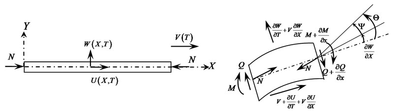
Where is the angle of rotation of cross section and can be expressed as for Timoshenko beam, is the shear angle. For Euler-Bernoulli beam, .
Without considering the coupling of longitudinal and transverse vibrations, the kinetic energy of the beam involves transverse vibration energy, rotational kinetic energy of cross section and the kinetic energy of rigid motion:
The components of potential energy involves potential energy due to compressive load, and strain energy of bending and shear:
According to Hamilton’s principle, the difference between the kinetic and potential energy is zero:
Substituting Eqs. (1) and (2) into Eq. (3), the expression of governing equations for axially moving Timoshenko beam under compressive load can be established based on the variational analysis in terms of axially moving speed and acceleration, but without derivative to load with respect to the axial coordinate and time:
where:
Substituting Eq. (4) into Eq. (5) yields the partial differential equations which contains transverse vibration only:
By introducing the dimensionless parameters:
Equation (7) can be expressed as dimensionless form:
where the dimensionless parameters , and associated with account for the effect of shear distortion, and represent the effect of rotary inertia and stiffness of the beam, respectively. Bending moment and shear force can be defined as , .
Equation (8) contains 1st to 4th order partial differential components of dimensionless axial coordinate and time, and the general solution in the form of separation of variables can be expressed as:
where is the mode shape function, and denotes the natural frequency of beam.
The dimensionless form of different boundary conditions are shown in Table A-1 in Appendix, and the static critical loads of each kind of support under compressive load are also given. It should be noted that the loads are true value for positive definite system (pinned-pinned, clamped-clamped, clamped-free) and for positive semi-definite system (free-free and pinned-free), critical load is assumed to be equal to that of pinned-pinned boundary condition for reference. Moreover, the positive semi-definite systems are assumed to be kept at steady state like flight vehicles, rigid motion of instability is restricted.
Boundary conditions used in reference [13] is a simplified form without taking into account of the impact of time-varying characteristics, which means the coefficient of is zero. Though it makes the equations easy to solve, the result is not so accurate. In the present work, the items of time-varying are included in the boundary conditions as shown in Table A-1.
3. Solving methods
3.1. Analytical solution of axial compressive load effect
The governing equation of transverse vibration of Euler-Bernoulli beam under axial compressive load can be translated to a dimensionless form for static beam as [14]:
where is the eigenvalue which has a series of solution with the form , and is the natural frequency of beam. represents the effect of compressive load and the general solution of Eq. (10) is:
where and are constant coefficients. The characteristic equations of each boundary conditions are obtained by substituting equations in Table A-1 into Eq. (11), as shown in Table A-2 in Appendix.
Defining the variable of load we have and Moreover, the dimensionless load factor is defined as the ratio of true load to critical load:
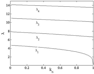
where is a coefficient depending on the boundary condition, it takes for pinned-pinned, pinned-free and free-free, for clamped-free and for clamped-clamped, as shown in Table A-1. There are no analytical solutions for equations in Table A-2 except pinned-pinned and pinned-free boundary conditions, for those cases the first order eigenvalue can be obtained with the variation of axial compressive load by numerical solution, as shown in Fig. 2.
It is shown in Fig. 2 that for clamped-clamped and free-free beams are the same. For all boundary conditions decreases slowly with the increasing axial load in the range of ; when the load is near to critical load as , decreases rapidly for all boundary conditions, when the load reaches to the critical load, decreases to 0. Thus, the axial load causes the beam stiffness decreasing and the first order frequency of elastic mode reduces to 0 when it reach to the critical load while the beam undergoes instability state. Translating the natural frequencies to dimensionless forms and the relationship between dimensionless frequencies and axial compressive load can be obtained:
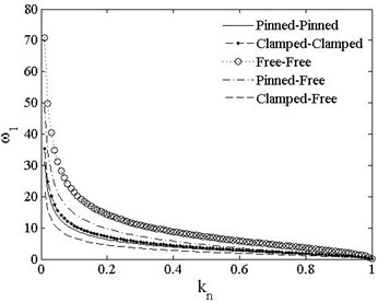
It is shown in Eq. (13) that is proportional to , but is inversely proportional to load , and is also dependent on factor of boundary condition. Fig. 3 presents the relationship between the first order dimensionless frequencies and the load factor . Since , , load factor is defined in the range of in this paper. is different from and it decreases rapidly when and more slowly when . decreases to 0 when . The results of analytical solution can be used to verify with the numerical methods.
Fig. 2λ1 vs. kn of different boundary conditions
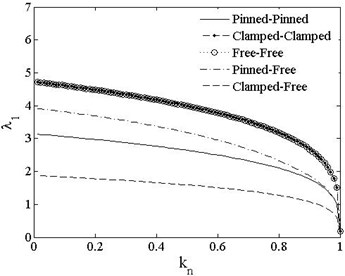
Fig. 3ω1 vs. kn of different boundary conditions
3.2. Modified Galerkin method (MGM)
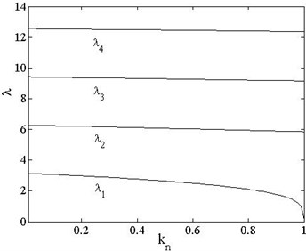
The Galerkin method can be used to solve Eq. (8), when its trial functions satisfy both force and displacement boundary conditions. The traditional Galerkin method takes mode functions of a static beam without axial load as its trail functions and thus leads to some inaccuracy for solving such problems. In this work, the Glaerkin method is modified by taking the mode functions of beam with load as its trail functions, and thus the present algorithm is called the Modified Galerkin method (MGM). Variation of the first four order roots with load factor can be obtained by solving equations in Table A-2 numerically, as shown in Fig. 4.
Fig. 4First four order eigenvalues vs. load of different boundary conditions
a) Pinned-pinned
b) Free-free
The 2nd, 3rd and 4th order eigenvalues decrease slowly with increasing compressive load and without significant drop like the 1st order eigenvalue when the load is close to the critical load, which indicates that the axial load has little effect on the higher-order eigenvalues other than the first order. Stiffness coefficient reaches its minimum value when the axial load closes to the critical one, and the contribution of the 1st order eigenvalue caused by compressive load reaches to a maximum value. Obviously, eigenvalues of non-axial load beam are just a special state of pre-loaded beam when .
Substituting equations of boundary condition in Table A-1 into Eq. (11) yields the mode functions of beam under compressive load, as shown in Table A-3 in Appendix. Equation (9) is rewritten as . is the Mode shape functions in Table A-3 which is used as the trail functions. From Eq. (8) we have:
where:
are all square matrix of th order, is the number of items of .
Equation (14) can be expressed in matrix form as:
where , is the coefficient matrix:
where and are the order zero matrix and unit matrix, respectively, and as a typical gyroscopic matrix, the translation exists for as follow:
The eigenvalue of matrix are pairs of complex numbers. According to Eqs. (14) and (15), the number of items for MGM truncation must be larger than the number of natural frequency order to be calculated, therefore, is determined to be 4 for the accurate calculation for the 1st and 2nd natural frequencies.
3.3. Differential quadrature method
Substituting Eq. (9) into Eq. (8) yields:
According to the differential quadrature method, th order derivative value of function at point can be expressed as a weighted sum of the value of all the nodes:
where presents the th order weight coefficients of derivative. is the function value at , is the number of nodes. Therefore, the first four order derivatives of mode functions of the nodes can be obtained by interpolation of the function values of the nodes as:
Non-uniform node distribution is used to discretize the beam and the method is introduced to deal with the boundary conditions, which is to add two nodes of distance from the two ends and renumber the nodes:
where [19]. The weight coefficients of DQM can be obtained through the Lagrange interpolation polynomial according to the interpolation principle. Expressions of the coefficients are:
Substituting Eqs. (21) and (22) into Eq. (17) yields:
Also, Eq. (23) can be translated to the matrix form as:
where, , are all th order square matrix, is the model function vector. Expression of elements in are:
where
For nodes at the two ends, i.e. since that the introduction of the time-varying items, not only elements in are affected, but also in and . According to Table A-1, elements in and are improved after introducing the boundary conditions with the axial compressive load. The DQM form of boundary conditions are shown in Table A-4 in Appendix.
Then solving of Eq. (24) is transformed to the generalized eigenvalue problem. The eigenvalues of Eq. (24) represents the dimensionless natural frequency of beam system.
4. Verification and discussion
An uniform thin-walled beam with rectangular cross-section is used for solutions and discussions. The beam’s configuration and material parameters are: , .
4.1. Verification of numerical methods
The beam in engineering can be classified into two types according to the positive definiteness property of boundary condition as mentioned before. Take one from each type of boundary conditions for example, i.e. the pinned-pinned beam for PDS, and the free-free beam for PSDS. The numerical results of MGM and DQM are compared with the analytical ones under , as shown in Fig. 5.
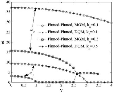
Fig. 5 shows that numerical results of MGM and DQM both agree with analytical results in the range of , thus these two numerical methods are both applicable for different boundary conditions. Fig. 6 shows the results of DQM and MGM for the pinned-pinned beam in the range of , the results for 1st and 2nd natural frequencies of these two methods are shown to agree with each other well. The DQM is used in the following numerical analysis while the number of nodes is set to 13 for convergence.
Fig. 5Comparison of DQM, MGM and analytical solutions ω1 vs. kn
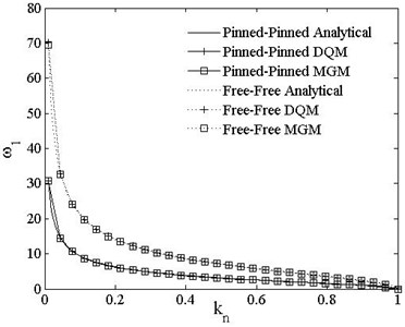
Fig. 6Comparison of DQM, MGM ω1,2 vs. v
4.2. Effect of axial compressive load
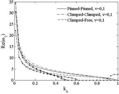
Fig. 7 indicates the variation of the 1st dimensionless complex frequency of PDS with axial compressive load. The complex frequencies of PDS are all real numbers with imaginary parts equal to 0 when axially moving speed is 0. The real part decreases rapidly in the range of and slowly when When the load reaches to the critical load as , reduce to 0, which indicates the critical load factor when. But for , the imaginary part of clamped-free beam is negative. With increasing moving speed for all boundary conditions the real part of the 1st frequency reduces to zero and it becomes unstable by the divergence instability of their imaginary parts when the load reaches the critical loads, which decreases to around half of the value of static beam.
Fig. 7The 1st dimensionless complex frequency of PDS vs. load vt=0, v=0, 1. v=0-- ; v=1-∙-
a)
b)
Fig. 8 indicates the variation of the 1st dimensionless complex frequency of PSDS with axial compressive load. As the cases in PDS, the frequency reduces with the increasing of moving speed. When , the critical loads of free-free and pinned-free beams reduce to and , repectively. The imaginary parts of those two conditions keep 0 before critical load when . When , it branches for free-free beam and the bifurcation point is the critical load point, but of pinned-free beam keeps rising with increasing load and it intersects the horizontal axis at the critical load point.
Fig. 8The 1st dimensionless complex frequency of PSDB vs. load vt=0, v=0, 1. v=0-- ; v=1-∙-
a)
b)
Fig. 9 indicates the variation of the imaginary parts of the fundamental modes of PSDS with axial compressive load. There exists two fundamental modes for free-free beam, one for in plane translational motion and the other for in plane rotation, while the pinned-free beam only has one for rotation. The real part of fundamental mode keep 0 for the two boundary conditions, and only the imaginary parts need to be discussed. For free-free beam, the imaginary frequency of the first mode of translational motion keeps 0, while that of the second mode of in plane rotation has slight increasing with for and has an obvious increasing when for For pinned-free beam, the imaginary frequency of in plane rotation keeps increasing in a small range with respect to for but it has a complex variation of bifurcation-combination-rebifuration phenomenon with the increasing of for .
Fig. 9Imaginary part of fundamental frequencies of PSDB vs. load vt=0, v=0, 1. v=0-- ; v=1-∙-
4.3. Effect of axially moving
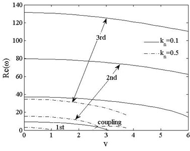
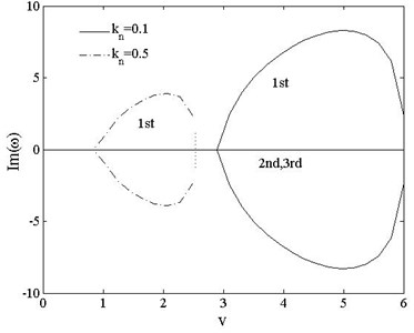
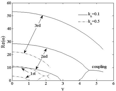
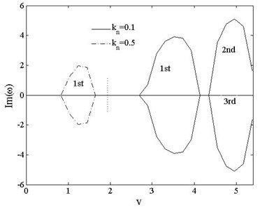
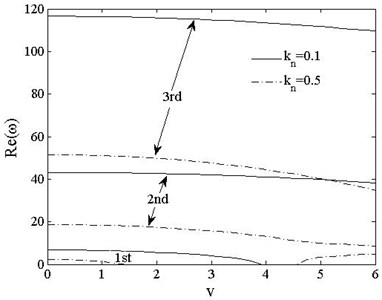
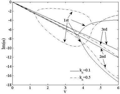
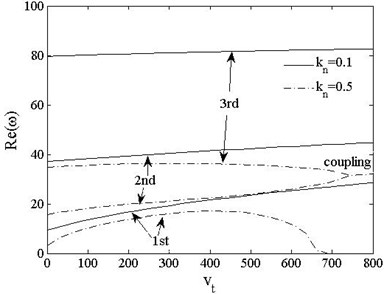
Figs. 10-12 show the variations of the first three dimensionless complex frequencies of PDSs boundary cases with axially moving speed when , . For all the three boundary cases, the real parts of , i.e. decrease with the increasing of speed. The reduces to 0 when the moving speed rises to the critical value and the supercritical value of speed The of three cases are 6.5, 2.8 and 3.9 when , the values decrease to 1.0, 1.1 and 1.3 when , which indicates that axial the compressive axial load affects the critical moving speed a lot. For , the 2nd and 3rd mode remain stable, but 1st mode is unstable with divergence instability. Special attention should be paid to the left parts of Fig. 10 for and Fig. 11 for . The 1st order regains stability when reaches , after that, the real parts of 1st and 2nd complex frequencies merge to each other while the imaginary parts bifurcate with positive and negative values, which indicates that the two order modes couple with each other and the beam undergoes coupled-mode flutter. For the clamped-free beam shown in Fig. 12, the real parts of 1st and 2nd complex frequencies get close but not merge together when reaches , and The of clamped-free beam keep negative as moving speed increasing and is different from the other two PDSs as a result of its asymmetric boundary condition.
Fig. 10The 1st, 2ndand 3rd dimensionless complex frequencies of pinned-pinned vs. speed vt=0, kn=0.1, 0.5
a)
b)
Fig. 11The 1st, 2ndand 3rd dimensionless complex frequencies of clamped-clamped vs. speed vt=0, kn=0.1, 0.5
a)
b)
Fig. 12The 1st, 2ndand 3rd dimensionless complex frequencies of clamped-free vs. speed vt=0, kn=0.1, 0.5
a)
b)
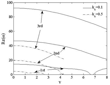
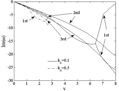
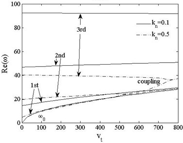
Fig. 13The 1st, 2ndand 3rd dimensionless complex frequencies of free-free vs. speed vt=0, kn=0.1, 0.5
a)
b)
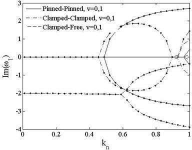
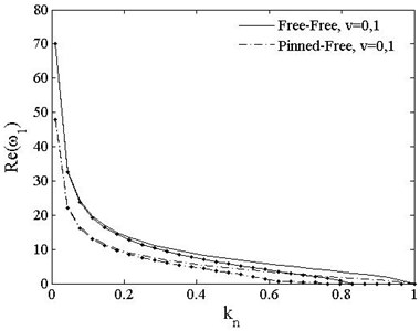
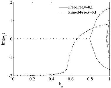
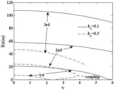
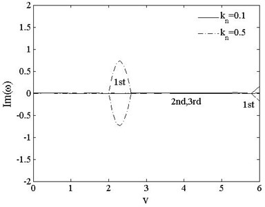
Figs. 13 and 14 show the variations of the first three order dimensionless complex frequencies of PSDSs boundary cases with axially moving speed when , . For free-free beam shown in Fig. 13, reduces from 5.9 to 2.2 when the compressive axial load rises from to For , when , the positive parts of 1st complex frequency keeps stable with value 0 while imaginary parts branches. When , reappears and rises up to couple with at . decreases with load increasing while and both remains 0.
Fig. 14The 1st, 2ndand 3rd dimensionless complex frequencies of pinned-free vs. speed vt=0, kn=0.1, 0.5
a)
b)
For the pinned-free beam shown in Fig. 14, is 6.6 under the load of , and branches and is asymmetric. The beam undergoes supercritical state when reaches to 6.9, 1st and 2nd frequencies are close to each other but do not couple. reduces to 2.6 when the compressive load increases to For all cases, and are positive while and are both negative and decrease with increasing speed.
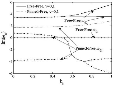
Fig. 15 show the variations of the fundamental modes of PSDSs boundary cases with axially moving speed when , . The 1st fundamental frequency of free-free beam remains 0, while the 2nd order frequency decreases slowly with increasing moving speed but rises sharply when near to for The branches when and merges at . The law of for those two boundary cases are similar, when the turning point moves forward.
Fig. 15Fundamental frequencies of PSDB vs. speed vt=0, kn=0.1, 0.5
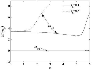
a) Free-free
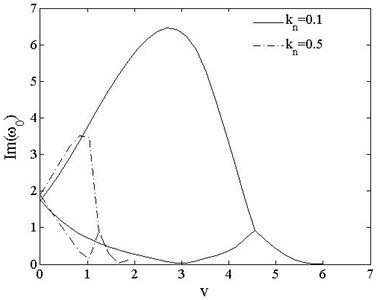
b) Pinned-free
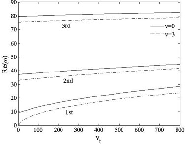
Figs. 16 and 17 show the variations of the first three dimensionless frequencies of pinned-pinned and pinned-free beams with axially moving acceleration when , . Fig. 16 indicates that the real parts of each order frequencies rise with the increasing moving acceleration when axial load is . When the load increase to , turns to decrease for and reaches 0 when , while the 2nd and 3rd modes couple each other which indicates that the beam undergoes coupled-mode flutter. For pinned-free beam, fundamental mode merges with the 1st elastic mode when , and the 2nd and 3rd modes couple at . Thus, the relationship between elastic modes and axially moving acceleration is complex under a nonlinear coupling with the axial compressive load.
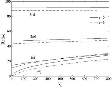
From Fig. 17, one can see that the real parts of each order rise with increasing moving acceleration. For of pinned-free beam is larger at than , which indicates that the effect of coupling speed and acceleration is not always linear.
Fig. 16Real part of the first three frequencies vs. acceleration kn=0.1, 0.5, v= 0
a) Pinned-pinned
b) Pinned-free
Fig. 17Real part of the first three frequencies vs. acceleration kn=0.1, v=0, 1
a) Pinned-pinned
b) Pinned-free
Fig. 18Fundamental frequencies of pinned-free beam vs. acceleration kn=0.1, 0.5, v=0, 3
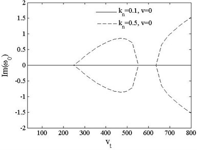
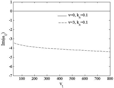
Fig. 18 shows the variations of the fundamental frequencies of pinned-free beam with axially moving acceleration when , and , . The branches when and this point agrees with . The remains 0 when and decreases with the increasing of acceleration when .
5. The critical loads and speeds
When the first elastic frequency reduces to zero, the beam reaches a critical state, and Eq. (8) becomes a time-independent equilibrium linear equation:
It can be simplified without taking into account of axially acceleration i.e. :
The roots of the characteristic equation of Eq. (27) is:
And the general solution of Eq. (27) is:
Equation (29) contains two parts, the first part denotes two types of foundational motion, i.e. lateral rigid motion, and the in-plane rotation. For PDS, the two foundational motions are limited. For PSDS, free-free beam have both foundational motions and pinned-free beam only has in-plane rotation. The second part denotes elastic modes.
Equation (27) can be expressed to a similar form of Eq. (10), where , . Then th eigenvalue can be obtained are obtained: , for pinned-pinned, pinned-free and free-free beams, for clamped-clamped beam, for clamped-free beams. By defining a new parameters , then , . Taking these items into the expression of the relationship between critical moving speed and axial compressive load can be obtained as:
And the variation of critical load to moving speed can also be obtained at the same time.
Fig. 19 shows the relationship between critical load and speed of clamped-free beam. It indicates that with the effect of axially moving and axial compressive load, the beam reaches critical state more easily. The critical value of speed or load can be approximately predicted from these results.
Fig. 19Critical load and speed of clamped-free beam
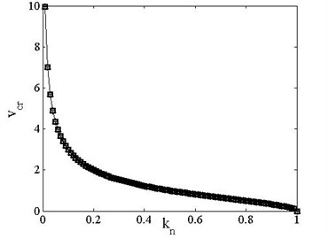
a) Critical speed vs. load
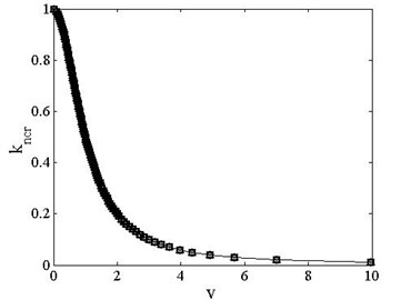
b) Critical load vs. speed
6. Conclusions
In this paper, the effect of compressive load on complex frequencies and stabilities of axially moving Timoshenko beam with different supports are studied,expressions of the critical load and speed for various boundary conditions are determined. Results of the study can be summarized as follows:
The real part of first three complex frequencies of five different boundary conditions decrease with the increasing compressive load and axially moving speed. The first two order modes of PDS conditions undergo coupled-mode flutter with increasing critical moving speed by divergent instability, while those of PSDS get closer but not merge together also. Rigid mode of PSDS undergoes instability with the increasing of compressive load and speed. The moving acceleration causes increasing of elastic and foundational frequencies.
Critical moving speed decreases with the increasing of the axial load, the critical load decreases with the increasing of axially moving speed, the coupling of these two effects causes the beam to reach instability state more easily.
References
-
Swope R. D., Ames W. F. Vibrations of a moving threadline. Journal of the Franklin Institute, Vol. 275, Issue 1, 1963, p. 36-55.
-
Mote Jr. C. D. A study of band saw vibrations. Journal of the Franklin Institute, Vol. 279, Issue 6, 1965, p. 430-444.
-
Lengoc L. Vibration of bandsaws. University of Canterbury, 1990.
-
Wickert J. A. Non-linear vibration of a traveling tensioned beam. International Journal of Non-Linear Mechanics, Vol. 27, Issue 3, 1992, p. 503-517.
-
Öz H. R., Pakdemirli M. Vibrations of an axially accelerating beam with small flexural stiffness. Journal of Sound and Vibration, Vol. 234, 2000, p. 521-535.
-
Öz H. R., Pakdemirli M., Boyacm H. Non-Linear vibrations and stability of an axially moving beam with time-dependent velocity. International Journal of Non-Linear Mechanics, Vol. 36, Issue 3, 2001, p. 107-115.
-
Kong L., Parker G. Approximate eigensolutions of axially moving beams with small flexural stiffness. Journal of Sound and Vibration, Vol. 276, Issue 2, 2004, p. 459-469.
-
Yang X. D., Chen L. Q. Determination of the natural frequencies of axially moving beams by the method of multiple scales. Journal of Shanghai University, Vol. 11, Issue 3, 2007, p. 251-254.
-
Lee U., Jang I. On the boundary conditions for axially moving beams. Journal of Sound and Vibration, Vol. 306, 2007, p. 675-690.
-
Simpson A. Transverse modes and frequencies of beams translating between fixed end supports. Journal of Mechanical Engineering Science, Vol. 15, 1973, p. 159-164.
-
Chonan S. Steady state response of an axially moving strip subjected to a stationary lateral load. Journal of Sound and Vibration, Vol. 107, Issue 1, 1986, p. 155-165.
-
Lee U., Kim J. H., Hyungmi O. Spectral analysis for the transverse vibration of an axially moving Timoshenko beam. Journal of Sound and Vibration, Vol. 271, Issue 3, 2004, p. 685-703.
-
Tang Y. Q., Chen L. Q., Yang X. D. Natural frequencies modes and critical speeds of axially moving Timoshenko beams with different boundary conditions. International Journal of Mechanical Sciences, Vol. 50, Issue 3, 2008, p. 1448-1458.
-
Bokaian A. Natural frequencies of beams under compressive axial loads. Journal of Sound and Vibration, Vol. 126, Issue 1, 1988, p. 49-65.
-
Bokaian A. Natural frequencies of beams under tensile axial loads. Journal of Sound and Vibration, Vol. 142, Issue 3, 1990, p. 481-498.
-
Zhang Y. Q., Lu Y., Ma G. W. Effect of compressive axial load on forced transverse vibrations of a double-beam system. International Journal of Mechanical Sciences, Vol. 50, 2008, p. 299-305.
-
Christian N. D., Shu D. W. Free vibration analysis of multiple delaminated beams under axial compressive load. Journal of Reinforced Plastics and Composites, Vol. 28, Issue 11, 2009, p. 1365-1381.
-
Pourtakdoust S. H., Assadian N. Investigation of thrust effect on the vibrational characteristics of flexible guided missiles. Journal of Sound and Vibration, Vol. 272, 2004, p. 287-299.
-
Sung K. J., Charles W. B., Alfred G. S. Application of differential quadrature to static analysis of structural components. International Journal for Numerical Methods in Engineering, Vol. 28, Issue 3, 1989, p. 561-577.
About this article

