Abstract
Longitudinally vibration ultrasonic motor (LV-USM), a canonical nonlinear system, utilizes the inverse piezoelectric effect of piezoelectric ceramic to generate the mechanical vibration within the scope of ultrasonic frequency. However, it is very difficult to establish a strict and accurate mathematical model. Hence seeking a dynamic identifier and controller for LV-USM avoiding the accurate mathematical model becomes a feasible approach. In this paper, a novel learning algorithm for dynamic recurrent Elman neural networks is present based on a particle swarm optimization (PSO) to identify and control an LV-USM. To overcome the PSO’s global search ability, Lévy flights, a kind of random walks, are imported to improve the ability of exploration rather than Brownian motion or Gauss disturbance based on Cooperative Quantum-behaved PSO (CQPSO). Thereafter, a controller is designed to perform speed control for LV-USM along with the nonlinear identification also using this kind of neural network. By discrete Lyapunov stability approach, the controller is proven to be stable theoretically and the latter trial shows its robustness of anti-noise performance. In the experiments, the numerical results illustrate that the designed identifier and controller can achieve both higher convergence precision and speed, relative to current state-of-the-art other methods. Moreover, this controller shows lower control error than other approaches while the displacement of the rotor disc in LV-USM appears more smooth and uniform.
1. Introduction
Ultrasonic Motor (USM), a canonical nonlinear system, utilizes the inverse piezoelectric effect of piezoelectric ceramic to generate the mechanical vibration within the scope of ultrasonic frequency. In general, it owns many excellent performances and useful features, such as high torque at low speeds, no electromagnetic interference, short start-stop times, and so forth [1-4]. Longitudinally vibration ultrasonic motor (LV-USM), is a typical intermittent contact USM [5, 6]. However, for this kind of nonlinear system, it is very difficult to establish a strict and accurate mathematical model on it not only because of its characteristics on mode shape, resonant frequency, contact stiffness, frictional characteristics, working temperature and other factors, but also not understand the inner friction mechanism [7]. Therefore, seeking a dynamic identifier and controller for USM avoiding the accurate mathematical model becomes a feasible approach.
Recently, recurrent networks focus the researchers’ attention not only because their dynamic equations are non-linear differential equations, but also high stability and robustness. The Elman neural network (ENN) is one of the simplest types among the available recurrent neural networks. Moreover, the NN approach can be applied widely to the specific tasks of USM’s identification and control since it is capable to tackle nonlinear behaviors not require any system’s a prior knowledge. To this end, the dynamic recurrent multilayer network introduces dynamic links to memorize feedback information of the history influence. This approach has great developmental potential in the fields of system modeling, identification and control [8, 9].
In this article, an Improved Elman neural network (IENN) is employed to identify and control an USM, and a novel PSO-based learning algorithm is proposed for training the IENN, so that the complex theoretical analysis of the operational mechanism and the exact mathematical description of the USM are avoided.
The remainder of this article is organized as follows: Section 2 provides a brief review on the longitudinal vibration ultrasonic motor and its state space equations. Section 3 proposes the CQPSO-LF to train the IENN. In section 4 we proposed a new speed control system based on IENN, then presents and discusses the numerical results from the experimental framework. Finally, section 5 offers our conclusions.
2. Longitudinal vibration ultrasonic motor (LV-USM)
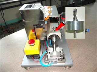
Longitudinal vibration ultrasonic motor (LV-USM) takes a vibration mode to generate a kind of elliptical motion from stator to rotor [5, 6]. The vibration is often achieved by the amplification of the piezoelectric strain usually either by the changes of vibration modal frequency or varies of phase difference between the piezoelectric elements. Due to the structure of LV-USM is very simple, more and more attentions turn to the design and producing of this kind of USM. Compared with the traveling wave type ultrasonic motor, the LV-USM is characterized by the trait of the simple structure, high efficiency, but also has a heavy drawback of a problem of friction since the contact point between the stator and the rotor is unique. The main experimental platform used in our work is illustrated as Fig. 1, which is composed by driven power supply, 89C51, programmable device, digital mobile phase signal generator, D/A converter, low pass filter, power amplifier circuit and other devices.
Fig. 1Experimental platform of LV-USM control system
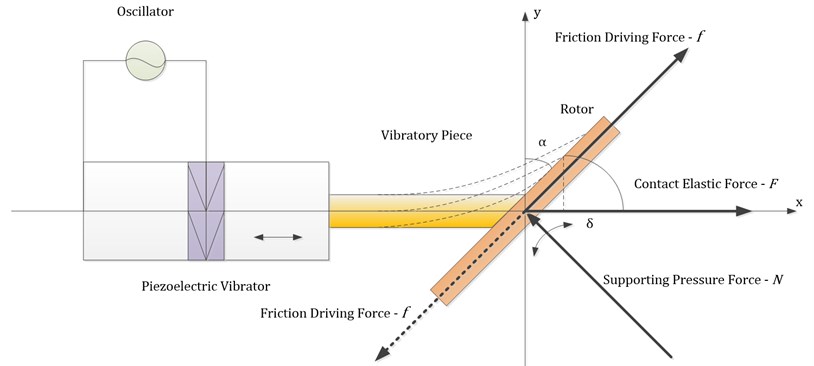
Considering a LV-USM, it consists of a left point-fixed stator beam and a rotor disc with a radius of . In the schematic diagram of LV-USM demonstrated by Fig. 2, a stator tip motion is desirable as it results in the stator imparting both a contact and tangential driving friction force on surface of the rotor, resulting in the desired stator/rotor output. The stator contacts with the rotor disc by a fixed angle. When the stator beam is triggered by its left piezoelectric element, it could move longitudinal along the horizontal direction. The mutual interaction occurs between the stator beam and rotor disc due to the touch, so the inherent frequency of stator beam could impacts the trajectory of end of the beam heavily. Under the frictional force of beam end, the rotor disc is driven to rotate.
Till recently, as a strict mathematical model of the typical intermittent contact USM has also not been established yet, so a lot of research centralized in the analysis and experimental fields. In reality, it is even difficult to obtain the idealized motion as illustrated in Fig. 2. It is far more common to keep the rotor in constant contact with the stator that ensures that the output obtained is repeatable for each stator cycle. Employing the model of coulomb friction [10], it could be seen that a cyclic contact force leads to a frictional driving force , as time averaged across one stator cycle, results in a network at the rotor in a given direction. Apart from the frictional driving force, a supporting pressure force is also exerted to the rotor when it is in stationary.
Fig. 2Schematic diagram of LV-USM
In this research, we assume that the longitudinal elastic deformation of the beam could not be ignored. So the contact elastic force of the beam could be computed in the following Equation (1):
where denotes there exists force between stator and rotor; but means the departure of them. In the latter case, there exists no any acting force between them and the stator vibrates freely. is the elastic coefficient of the beam along the longitudinal axis. is the deformation when the stator contact the rotor at the beginning. is a sine-like longitudinal deformation of the stator’s end when motivated by the left piezoelectric element, while the lateral bending displacement.
From the vibration theory, we can know the state space equations for the longitudinal oscillation ultrasonic motor as the following Eq. (2) to Eq. (6) according to literature [11]:
where denotes the elastic force of the stator in the longitudinal direction; is axial compressive force assumed to be equal to ; means the driving force produced by the resultant force parallel to the rotor surface. represents the resultant force parallel to the rotor surface. is the friction coefficient during the sticking phase. is the Young’s modulus of elasticity. is the Dirac delta function. At last, is the velocity of the end of the stator.
3. Elman neural network based on CQPSO with Lévy flights
3.1. CQPSO with Lévy flights
Particle swarm optimization (PSO), originally introduced by Kennedy and Eberhart [12], has become one of the most important swarm intelligence algorithms. The unique information diffusion and interaction mechanism of PSO enable it to solve many problems with good performance at low computational cost. Based on the rationale of Cooperative Co-evolutionary Genetic Algorithm (CCGA) in [13], Van den Bergh introduced the Cooperative PSO that employs a kind of cooperative behavior to significantly improve the performance of the original algorithm [14]. Compared to basic single swarm PSO, both robustness and precision are improved and guarantied. The key idea of CPSO is to divide all the -dimension vectors into sub-swarms. So the front swarms are -dimensional, and the swarms behind have -dimensional vectors. In each pass of iteration, the solution is updated based on sub-swarms rather than the original one. When the particles in one sub-swarm complete a search along some component, their latest best position will be combined with other sub-swarms to generate a whole solution.
However, PSO and CPSO is not a global optimization algorithm [14]. In literatures [15, 16], Sun et al. proposed a quantum-behaved PSO (QPSO) algorithm, which can be guaranteed theoretically to find optimal solution in search space. The experimental results on some widely used benchmark functions show that the QPSO works better than standard PSO [15, 16] and should be a promising algorithm.
Usually, the technique of random disturbance is imported to improve the performance of PSO or QPSO. Typically, the Gaussian and Cauchy probability distribution disturbance have been used to avoid premature convergence. In [17], the random sequences in QPSO were generated using the absolute value of the Gaussian probability distribution with zero mean and unit variance. Based on the characteristic of QPSO, the variables of the global best and mean best positions are mutated with Cauchy distribution, and an adaptive QPSO version was proposed in [18].
In this paper, another random walk method, Lévy flights, is employed to do this work. Lévy flights, named after the French mathematician Paul Pierre Lévy, are Markov processes [19]. After a large number of steps, the distance from the origin of the random walk tends to a stable distribution. Lévy flights, which can be characterized by an inverse square distribution of step length, may optimize the random search process when targets are scarce and scarcity of resources. In contrast, Brownian motion is usually suit for the case when need to locate abundant prey or targets. These traits of two random walks inspired us to improve our swarm intelligence optimization, where Lévy flights can improve the ability of “exploration” while Brownian motion benefits the “exploitation”.
Mathematically, Lévy flights are a kind of random walk whose step lengths meet a heavy-tailed Lévy alpha-stable distribution, often in terms of a power-law formula, , where 02 is an index. A typical version of Lévy distribution can be defined as according to reference [20]:
As the change of , this can evolve into one of Lévy distribution, normal distribution and Cauchy distribution.
Taking the 2D-Lévy flights for instance, as shown in Fig. 3(c), an instance of the trajectory of 500 steps of random walks obeying a Lévy distribution. The steps follow a Lévy distribution as in Fig. 3(b), while the directions of its movements meet a uniform distribution as in Fig. 3(c). Note that the Lévy flights are often efficient in exploring unknown and large-scale search space than Brownian walks. One reason for this argument is that the variance of Lévy flights increases faster than that of Brownian random walks, i.e. . Also, compared to Gaussian distribution, Lévy distribution is advantageous since the probability of returning to a previously visited site is smaller than for a Gaussian distribution, irrespective of the value of chosen.
Fig. 32D Lévy flights in 500 steps
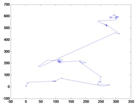
(a) Distance
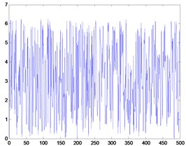
(b) Step lengths
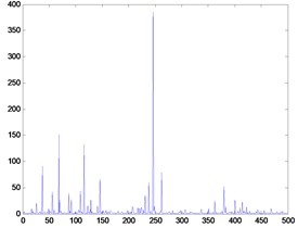
(c) Angle values
In CQPSO algorithm proposed in [21], an electoral swarm is generated by the voting of primitive sub-swarms and also participates in evolution of swarm, whose candidate particles come from primitive sub-swarms with variable votes. From the update strategy of CQPSO-LF, we can draw a conclusion that all particles in CQPSO-LF will converge to a common point, leaving the diversity of the population extremely low and particles stagnated without further search before the iterations is over. To overcome the problem, we exert a disturbance generated by Lévy flights on the mean best position, global best position and electoral best position when the swarm is evolving as shown in the following Eq. (8)-Eq. (10). To the local attractor, the hop steps in Lévy flights promise the random traversal in the search space. However, to the global and electoral best location, they only need a slightly disturbance, i.e. the angles meet a uniform distribution, to exploit the particles nearby:
where , , , is a pre-specified parameter, is a number in a sequence by Lévy flights, is the angles of directions in Lévy flights.
Differently with other similar methods, we use the output parameters of Lévy flights to intervene the position change directly, which can be seen in the Eq. (11) as follow, where and are the output parameters of Lévy flights which are random generated:
3.2. Elman neural network trained by CQPSO-LF
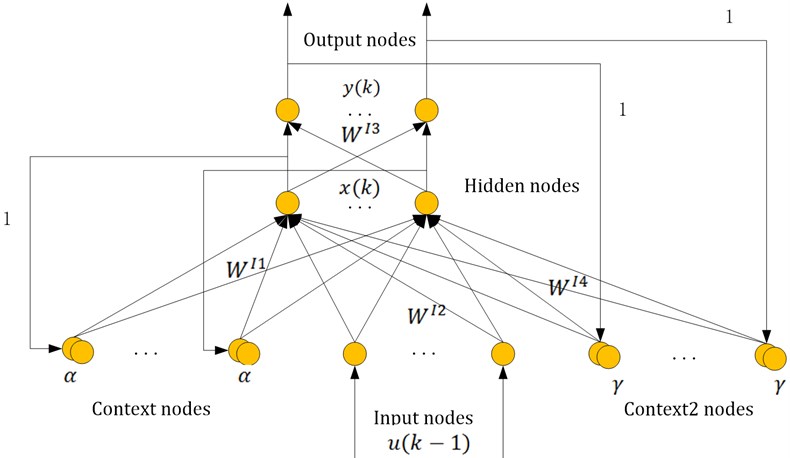
In the standard Elman NN (ENN) model, only the feedbacks of hidden nodes is considered, regarding less of those of the output nodes. As the feedbacks of every layer of neurons may affect the signal processing ability of network, so in the literature [11], a new Improved Elman NN (IENN) was developed as shown in Fig. 4. From the topologic of IENN, the feedbacks of output nodes, called context units are also added in the first layer, along with the input nodes and context units1. is the self-connection feedback factor whose weight is denoted as .
Fig. 4Architecture of the IENN
The mathematical model of this IENN is as follows:
The modifier formulas of is similar to the traditional Elman NN, as such:
where is the learning step-length of . Other notations can be seen in the work [11].
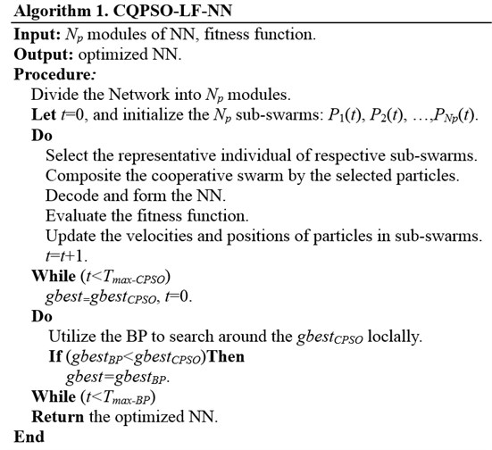
Now, considering the th module, as it is the part between layer and , so it is optimized by the . In our algorithm, an approach of binary encoding is adopted to represent the structure of NN, i.e., the connective relations between nodes, while real number encoding for the linked weights.
Let the node number of layer is , then the connective relations can be denoted by a matrix . If , then it represents there exists a link between the node in layer to the node in layer ; otherwise, if , then there exists no any link between them. Consequently, the structure encoding of individual in the th sub-swarm’s can be denoted by . In this research, the target is to design a proper NN under the condition of a given group of input/output pairs to make the output of NN approximate the given data as close as possible. Let note the input/output pairs as (), , and when the input is , the real output of NN is . Considering the th sub-swarm , the th individual , the representative ones from other sub-swarms, , then the fitness value of the can be defined as below:
Fig. 5Pseudocode of the CQPSO-LF-based learning algorithm for IENN
4. Velocity control of longitudinally vibration ultrasonic motor
4.1. Design of the speed control system and stability analysis
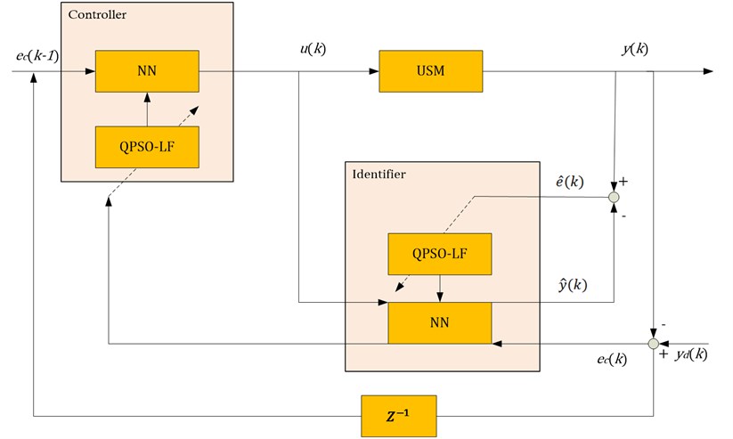
In this section, we proposed a new speed control system based on IENN, which can provide a channel for error reverse transmission. The proposed control model can be applied to any type of nonlinear systems especially when a direct controller cannot be designed due to the complexity of the process. The USM is still considered as an example of a highly nonlinear system to test the performance of the proposed controller. The block diagram of the speed control system is illustrated in Fig. 6. In the developed control system, the IENN is trained online by the CQPSO-LF algorithm, proposed in Section 3, and the driving frequency is taken as the control variable.
As shown in Fig. 6, the controller output the signal as the input of the identifier, whose output is . During the procedure of controlling, could be obtained after the online learning algorithm proposed in the previous section, then the training error could be evaluated as . On the other hand, the NN in the controller only own one input parameter, i.e., as the system error at last time. Suppose the is the expected output of USM, and let difference of the real output be , i.e., . Hereinafter, the system error function is defined as .
Fig. 6Block diagram of the speed control system
During the control process, it is required that all the time. Note that:
so for simplification, using to represent the and . Because the input is also the function of , so it is a recursive procedure. The concrete analysis is as follows:
To make , only let , where the is the learning step length. In brief, the learning algorithm could be summarized as:
4.2. Stability analysis
In general, choose of learning rate is very important to the performance of the neural network. Too small learning rate may lead to the network running slowly, but large one also results the instability of the network. In order to train the IENN effectively, we proposed an adaptive learning rate which can guarantee the stable convergence of the IENN on the basis of discrete Lyapunov stability approach. Now, let’s discuss the stability of IENN.
According to the learning algorithm of , we can get:
then
Easy to see that when , In accordance with discrete Lyapunov stability approach, when , the training error will converge to 0. Similarly available, if , it could guarantee the convergence of in the learning algorithm. Based on the above equations, it can be seen that when , minimizes, i.e., it can guarantee convergence with the fastest speed, and vice versa in the case of .
4.3. Numerical experiments
The experimental results of speed control by the proposed approach are shown in this subsection.
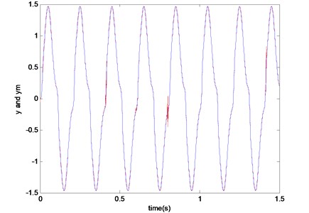
Fig. 7 shows the numerical result for adjustable-speed control when the commanded speed was changed in a wide speed range the same with the case in IENN control. The artificial neural network achieves the fine control performance in all the extent of speed range under a given sinusoidal-like input signals.
Fig. 7Adjustable-speed control by artificial neural network
Then the functional relation between the control input of the object and the controlled value is also considered. Because of the short responsive time of the LV-USM, control input of the object can reach the stable status on the excitation signal quickly. Fig. 8 gives the response curves in the simulated results in Matlab 7.8 under two different configures of the parameters for the controller. From that, we can see the control input of the object and the controlled value show a nonlinear step relation, which is very sensitive with the control parameters. In some cases, the control input signal may result in a kind of linear attenuation due to the wrong parameter, which may do harm to the whole performance of the control system.
Fig. 8Control input of the object and the controlled value
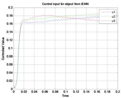
a)
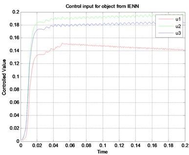
b)
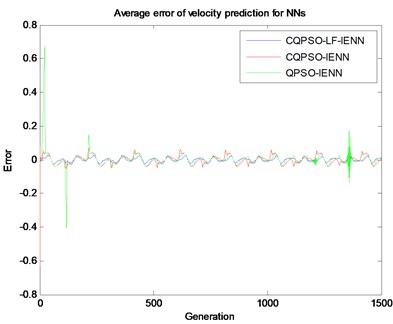
In Fig. 9, comparisons for the average error of velocity prediction are made among the existing typical stochastic algorithms. Fig. 9(a) compares the average error with IENN, GA-IENN and PSO-IENN. It can be seen that the IENN’s average error is not stable and shows the convergence properties, while the GA-IENN and PSO-IENN show better stability and constant. Fig. 9(b) explains the cases of the trained IENN by the variants of PSO learning algorithms, where all average errors of the three methods are smaller than those in Fig. 9(a). Moreover, it can be found that the pure QPSO may bring about some instantaneous stochastic perturbations in the generations of iteration.
Fig. 9Average error of velocity prediction from NNs
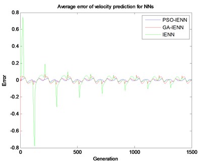
a)
b)
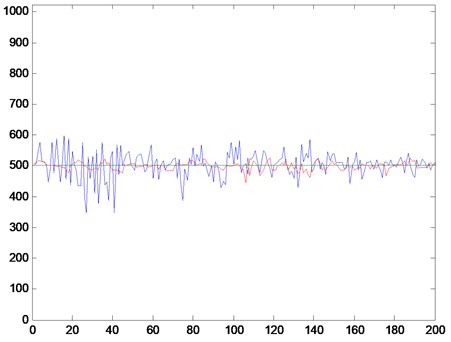
Fig. 10 shows the USM speed curves compared by the case with and without the control. In the figure, the blue line represents the speed curve without control, in which the amplitude of severe oscillation is obvious. The red line illustrates the speed control curve by our system, where the amplitude of the speed fluctuation using the proposed method is significantly smaller. From the two curves it can be seen that the proposed controller performed successfully and possesses a high control precision to approximate the value of expectation better.
Fig. 10LV-USM speed curves compared by the case with and without the control
The mutual interaction occurs between the stator beam and rotor disc due to the touch, so the inherent frequency of stator beam could impacts the trajectory of end of the beam heavily. Under the frictional force of beam end, the rotor disc is driven to rotate. To reflect this kind of interaction force and vibration, we choose another perspective to look insight into the law, i.e., by the viewpoint of the displacements on the rotor disc.
To make the discussion facility, a rectangular region on the rotor disc is considered. So according the vibration analysis approach of rectangular plates, the steady state transverse displacement, , subjected to the excitation at is as below. The notations in this equation could refer to the literature [22].
Fig. 11 illustrates the landscape of the displacements on coordinates , where Fig. 11(a) is the case without any control and the Fig. 11(b) the case under the charge of our speed control system. According to the graphs, we could draw a conclusion that the controller could suppress the vibration effectively from the displacement of the rotor disc in LV-USM which appears more smooth and uniform.
Fig. 11Landscape of the displacements on (x,y) of the rotor disc
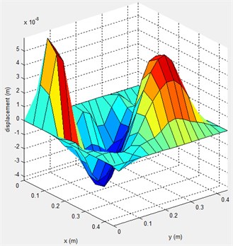
a) The case without control
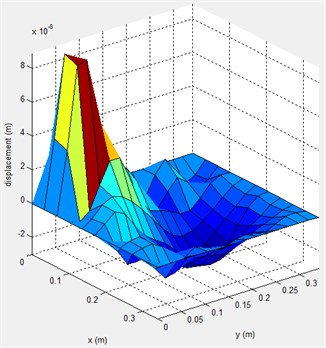
b) The case with our control system
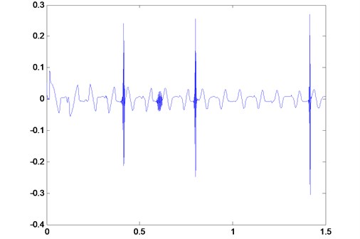
For the sake of verifying preliminarily the robustness of the proposed control system experimentally, we examine the response of the system when an instantaneous perturbation is added into the control system. Fig. 12 shows the speed control curve when the driving frequency subjected to an instantaneous stochastic perturbation during the running time which occurred 4 times. A short time after the burr signals generated, the control curve could make a rapid convergence. It can be seen that the control model owns an adaptive ability against the perturbation on the frequency of the driving voltage. Therefore, this controller presented here exhibits a robustness of anti-noise performance and can handle a variety of operating conditions without losing the ability to track accurately a desired course.
Fig. 12Speed control for randomly instantaneous disturbance
5. Conclusions
In this article, we adopt an Improved ENN (IENN) to identify and control the LV-USM. From the topologic of IENN, the feedbacks of output nodes are added in the first layer, along with the input nodes and context units. In the CQPSO-based learning algorithm, we employ the Lévy flights to improve the ability of “exploration” rather than Brownian motion or Gauss disturbance. Some experiments show that this variant of CQPSO outperforms other algorithms. Based on this kind of IENN, a new speed control system could provide a channel for error reverse transmission working together with an identifier also using IENN. By discrete Lyapunov stability approach, this controller is proven to be stable theoretically and the latter trial shows its robustness of anti-noise performance. In the real experiments, the numerical results illustrate that the designed identifier and controller can achieve both higher convergence precision and speed, relative to current state-of-the-art other methods. Moreover, this controller could suppress the vibration effectively from the displacement of the rotor disc in LV-USM which appears more smooth and uniform.
References
-
Sashida T., Kenjo T. An introduction to ultrasonic motors. Oxford, Clarendon Press, 1993.
-
Lino A., Suzaki K., Kasuga M., Suzuki M., Yamanaka T. Development of a self-oscillating ultrasonic micro-motor and its application to a watch. Ultrasonics, Vol. 38, Issue 1-8, 2000, p. 54-59.
-
Hemsel T., Wallaschek J. Survey of the present state of the art of piezoelectric linear motors. Ultrasonics, Vol. 38, Issue 1-8, 2000, p. 37-40.
-
Lin F. J., Wai R. J., Hong C. M. Identification and control of rotary traveling-wave type ultrasonic motor using neural networks. IEEE Trans Control Syst Technol, Vol. 9, Issue 4, 2001, p. 672-680.
-
Park S., He S. Standing wave brass-PZT square tubular ultrasonic motor. Ultrasonics, Vol. 52, 2012, p. 880-889.
-
Watson B., Friend J., Yeo L. Piezoelectric ultrasonic micro/milli-scale actuators. Sensors and Actuators A: Physical, Vol. 152, 2009, p. 219-233.
-
Senjyu T., Miyazato H., Yokoda S., Uezato K. Speed control of ultrasonic motors using neural network. IEEE Trans Power Electron, Vol. 13, Issue 3, 1998, p. 381-387.
-
Xiong Z. H., Zhang J. A batch-to-batch iterative optimal control strategy based on recurrent neural network models. Journal of Process Control, Vol. 15, Issue 1, 2005, p. 11-21.
-
Lin F. J., Wai R. J., Chou W. D., Hsu S. P. Adaptive back stepping control using recurrent neural network for linear induction motor drive. IEEE Trans and Electron, Vol. 49, Issue 1, 2002, p. 134-46.
-
Trinkle J. C., Pang J. S., Sudarsky S., Lo G. On dynamic multi-rigid-body contact problems with coulomb friction. Math. Mech., Vol. 77, 1997, p. 267-279.
-
Shi X. H., Liang Y. C., Xu X. An improved Elman model and recurrent back-propagation control neural networks. Journal of Software, Vol. 11, Issue 6, 2003, p. 1110-1119.
-
Kennedy J., Eberhart R. Particle swarm optimization. Proceedings of the IEEE International Conference on Neural Networks, Vol. 4, 1995, p. 1942-1948.
-
Keerativuttitumrong N., Nachol C., Vara V. Multi-objective co-operative co-evolutionary genetic algorithm. Parallel Problem Solving from Nature – PPSN VII. Springer, Berlin Heidelberg, 2002, p. 288-297.
-
Van den Bergh F., Engelbrecht A. P. IEEE Transactions on Evolutionary Computation 8, 2004, p. 225.
-
Sun J., Feng B., Xu W. B. IEEE Proceedings of Congress on Evolutionary Computation, 2004, p. 325.
-
Sun J., Xu W. B., Feng B. Cybernetics and Intelligent Systems Proceedings of the 2004 IEEE Conference, 2004, p. 111.
-
Coelho L. D. S. Novel Gaussian quantum-behaved particle swarm optimizer applied to electromagnetic design. Science, Measurement & Technology, Vol. IET 1, 2007, p. 290-294.
-
Liu J., Sun J., Xu W. B. Design IIR digital filters using quantum-behaved particle swarm optimization. Advances in Natural Computation, LNCS, Vol. 4222, 2006, p. 637-640.
-
Jamil M., Zepernick H. J. Levy flights and global optimization. Swarm intelligence and bio-inspired computation: theory and applications. London, 2013, p. 49-72.
-
Yang X. S., Deb S. Cuckoo search via Lévy flights. Nature & Biologically Inspired Computing, 2009. p. 210-214.
-
Li D., Deng N. An electoral quantum-behaved PSO with simulated annealing and Gaussian disturbance for permutation flow shop scheduling. Journal of Information & Computational Science, Vol. 9, Issue 10, 2012, p. 2941-2949.
-
Arenas J. P. On the vibration analysis of rectangular clamped plates using the virtual work principle. Journal of Sound and Vibration, Vol. 266, Issue 4, 2003, p. 912-918.
About this article

The research was supported by the Natural Science Foundation of Anhui Province (No. 1308085QF103), the Natural Science Foundation of Educational Government of Anhui Province (No. KJ2013B073), the Science and Technology Plan Project of Chuzhou City (No. 201236), and the Talent Introduction Special Fund of Anhui Science and Technology University (No. ZRC2011304). It also was partly supported by the National Natural Science Foundation of China (No. 61201250) and Guangxi Natural Science Foundation of China (No. 2012GXNSFBA053174). The authors sincerely thank the anonymous reviewers for their constructive comments and helpful suggestions.
