Abstract
Severe skidding of high-speed roller bearings (HSRBs) in a whirling squeeze film damper often leads to vibration and failure of rotor-bearing systems or even entire machines. In this manuscript, the skidding failure of HSRBs, especially considering bearing whirl, was studied. Analytical models were built by taking bearing whirl into account, and the skidding mechanism was investigated systematically in terms of various factors such as whirl orbit, radial load, lubricating oil viscosity, roller diameter, diametral clearance, roller length, and number of rollers. The results showed that whirl might lead to unstable movements, which can exacerbate skidding damage to the bearing, and the degree of skidding is directly correlated with the whirl radius. As radial load and diametral clearance increase, the degree of skidding and the influence of whirl motion on bearing skid decrease. In contrast, as the roller diameter, roller length, and number of rollers decrease, the degree of skidding and the influence of whirl motion on bearing skid decrease. Furthermore, the analysis results show that the viscosity of lubricating oil has both positive and negative effects on bearing skid. Therefore, for reducing bearing skid to improve HSRB service life and stability, the whirl radius, roller diameter, roller length, and number of rollers should be decreased, whereas the radial load and diametral clearance should be increased moderately.
1. Introduction
For meeting the requirements of high performance rotating machinery, attention has been focused on the roller bearings characterized by higher speeds, lower vibration and noise, and longer service life. One of the challenges to this end is tackling bearing skid, which often occurs under high and ultra-high speeds. Extreme sliding between the roller and the raceway can lead to wear on the rolling contact surfaces and subsequently result in smearing type of surface damage [1]. Many researchers have studied the skidding failure of high-speed roller bearings (HSRBs). Dowson and Higginson analyzed the effects of film thickness and frictional forces on cage slip and derived equations for calculating the various forces acting on a roller under the rigid and elastohydrodynamic lubrication regimes [2]. Harris and Kotzalas proposed an analytical method for predicting skid in HSRBs; this method yielded good results under the conditions of medium and excess loading [3, 4]. Hamrock and Jacobson analyzed the effect of curvature on cage and roller slip [5]. Given the high slip velocities at the rolling element–cage contact, a constant friction coefficient was used for this contact [6]. Mukhopadhyay and Bhattacharya performed visual observation, chemical analysis, macro- and microstructure characterization, hardness profile measurement, fractography, and energy dispersive spectroscopy (EDS). They found that roller pins fail owing to fatigue crack initiation at the welded joint. This initiation was ascribed to the presence of untempered martensite resulting from an improper welding process [7]. Tu et al. presented an analytical model for investigating skidding during acceleration of a rolling element bearing that considered the contact force and friction force between the rolling elements’ races and the cage, gravity, and the rolling elements’ centrifugal force [8]. The authors analyzed various factors that influence skid and developed HSRB skidding analysis software [9-10].
Most above mentioned theoretical analyses assume that rolling bearings are installed directly in the bearing house, which is the ideal operating condition. For satisfying the demand of increased production, the speeds of rotor-bearing systems with rolling bearings have been increased consistently. Theoretically, rotor-bearing systems can maintain stable operation even when the rotor speed is above the system’s critical speed. However, in practice, owing to a few unbalanced factors, strong vibration, noise, and instability are induced in a system at rotor speeds higher than the critical speed. Therefore, for reducing vibration and improving reliability and service life of the mechanical system, squeeze-film damper bearings (SFDBs) are usually used for supporting high-speed rotors [11, 12]. In general, the inner ring of a SFDB is mounted on the outer ring of a rolling bearing with an interference fit. Therefore, whirling of the inner ring induces bearing whirl. At high speeds, whirling of the inner ring inevitably has an effect on the skidding failure of bearings.
Many studies have focused on HSRB skidding analysis without considering bearing whirl. The authors of the present study considered the situation of bearing whirl involving a cylindrical roller bearing as an example and built a skidding analysis model considering bearing whirl and investigated skidding failure mechanisms in terms of various factors such as whirl orbit, radial load, lubricating oil viscosity, diametral clearance, roller diameter, roller length, and number of rollers.
2. SFDB model
SFDBs are widely used for attenuating vibration and improving the stability of rotating machinery and can be classified into two generic groups: centralized and uncentralized. The essential part of SFDBs comprises a lubricated cylindrical pair; the inner ring translates without rotating in the gap of this pair. The typical structure of uncentralized SFDB is shown in Fig. 1. A rotating shaft carries a rolling bearing, the outer ring of which whirls with the inner ring of the SFDB in the oil-filled clearance space between the inner and outer rings of the SFDB. The outer ring of the rolling bearing forms a damper journal whose rotation is prevented using an anti-rotation pin. As a consequence of the damper journal motion, a pressure field is established in the oil film [13, 14].
Fig. 1Structure of uncentralized SFDB
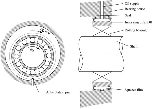
As can be seen, SFDBs’ damping effect mainly relies on an inner ring whirl, which squeezes the oil film in the clearance space and generates resistance from the film. In general, the inner ring of a SFDB is mounted on the bearing outer ring with an interference fit; doing so ensures that all of them whirl together, thus inevitably influencing bearing skidding failure.
3. Skidding analysis of HSRB in whirling squeeze film damper
3.1. Basic assumptions
In this manuscript, the HSRB of a whirling squeeze film damper is taken as an example, and the assumptions are as follows:
(1) Treat the contact between roller and raceway as a rigid contact,
(2) The roller purely rolls along the outer ring raceway in the unloaded zone of the bearing. Thus:
(3) The cage normal forces and acting on every roller are equal in the unloaded and the loaded zones, respectively. Thus:
3.2. Whirl orbits
Bearing whirl is majorly stimulated by shaft rotation. Therefore, the whirling frequency is relevant to shaft speed. In related research, Zhang et al. and Defaye et al., considered the example of a roller, as shown in Fig. 2, and assumed its whirl orbits to be a circle with radius with simple harmonic vibration in the and directions [15-16].
Fig. 2Whirling roller in SFDB
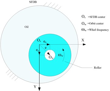
Take the time of the maximum amplitude as the initial moment; thus, the coordinates of orbit center can be expressed as follows:
So:
3.3. Kinematics and mechanical models of the roller
The roller whirls along with the bearing. The kinematics model of a roller is shown in Fig. 3, and the forces acting on a roller at angular location are shown in Fig. 4.
Consider a separate roller as an analysis object; its kinematics model is shown in Fig. 3. Thus, the sliding velocities can be expressed as follows:
Fig. 3Kinematics model
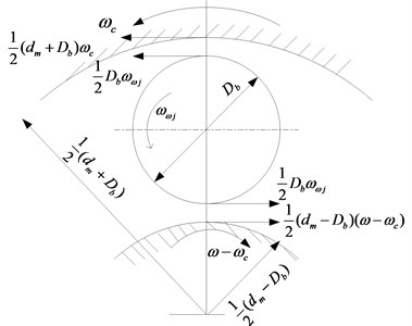
Fig. 4Mechanical models
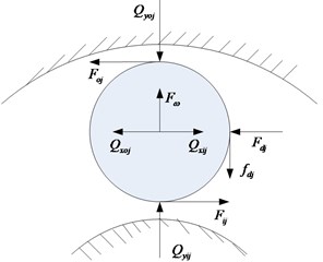
a) Loaded zone
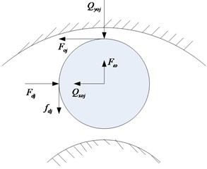
b) Unloaded zone
Additionally, the fluid entrainment velocities are defined as follows:
The sliding and the fluid entrainment velocities can be expressed in terms of dimensionless quantities as follows:
In the loaded zone, the dynamic balance equations are expressed as follows:
In the unloaded zone, the dynamic balance equations are expressed as follows:
Eqs. (15)-(20) can be expressed in terms of dimensionless quantities.
In the loaded zone:
In the unloaded zone:
For entire rollers:
In which:
where and denote normal forces transmitted by the raceways to the roller owing to bearing radial load and geometry. The Dowson-Higginson formulas [2] are adopted here:
Here, and indicate dimensionless film thicknesses defined by Dowson and Higginson [2] as follows:
In which:
Eqs. (22) and (25) can be further substituted into Eq. (27), and then Eqs. (23), (26), and (27) form an equation set with equations. Then, the cage speed and cage slip fraction can be obtained by combining Eqs. (5) and (6) with the kinematic equations, load equations, Dowson-Higginson formulae, and other related equations and solving by the Newton-Raphson method [3, 9-10].
4. Analysis and discussion
In this study, a single-row cylinder roller bearing is considered as an example for skidding analysis, and the default parameters are listed in Table 1. Parameters such as , , , and in Table 1 can be varied to analyze the effects of different structure parameters on the skidding of HSRBs considering bearing whirl.
Table 1Default parameters
(m) | (m) | (m) | (Pa) | |
0.045 | 0.089 | 0.065 | 5000 | 2.28e11 |
(kg/m3) | (m) | (m) | (pa·s) | |
7800 | 0.01 | 16 | 5e-5 | 0.08 |
The cage slip fraction can be expressed as follows:
4.1. Skidding analysis under different whirl radius and considering whirl or not
As shown in Fig. 5, the values of cage speed and cage slip fraction vary with time because of whirl. Furthermore, whirl leads to the generation of additional forces in roller-cage and roller-ring pairs. These forces oscillate over time, which may affect bearing fatigue life. More importantly, the magnitudes of the roller-rings and roller-cage oil film forces oscillate as well. Additionally, Fig. 5 shows that the degree of bearing skid varies directly with the whirl radius. This is because the force induced by whirl motion decreases as the whirl radius decreases. That is, whirl has little influence on bearing skid. For improving bearing service life and reliability, the whirl radius should be reduced moderately.
Fig. 5Skidding analysis under different whirl radii (n= 5000 r/min; Fr= 500 N)
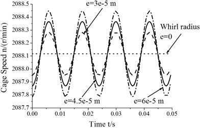
a) Cage speed vs. whirl radius
b) Cage slip fraction vs. whirl radius
4.2. Skidding analysis under different radial loads
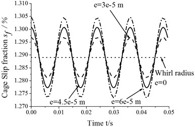
Fig. 6 shows that the amplitudes of cage speed and cage slip fraction decrease with an increase in the radial load. In other words, the influence of whirl on bearing skid dereases as the radial load increases. In contrast, the cage speed increases as the radial load increases, but the cage slip fraction shows a reverse trend. Therefore, the degree of skid can be reduced by suitably increasing the radial load.
Fig. 6Skidding analysis under different radial loads (n= 5000 r/min; e= 4.5e-5 m)
a) Cage speed vs. radial load
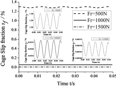
b) Cage slip fraction vs. radial load
4.3. Skidding analysis considering different lubricating oil viscosities
Fig. 7 shows that the amplitudes of cage speed and cage slip fraction decrease as the viscocity increases. In other words, whirl has a smaller influence on bearing skid as viscosity increases. In contrast, cage speed decreases as viscosity increases, whereas the cage slip fraction shows a reverse trend. It is obvious that viscosity has both positive and negative effects on bearing skid. Therefore, it should be decided only after comprehensive situation-specific consideration for reducing the degree of skid. In this case, whirl has a smaller influence on bearing skid than viscosity. That is, viscosity has a leading role in bearing skid, and this role expands as the viscosity increases.
Fig. 7Skidding analysis in different viscosity of lubricating oil (n= 5000 r/min; Fr= 500 N; e= 4.5e-5 m)
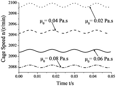
a) Cage speed vs. viscosity
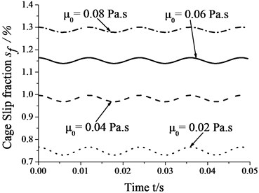
b) Cage slip fraction vs. viscosity
4.4. Skidding analysis with different roller diameters
Fig. 8 shows that the amplitudes of cage speed and cage slip fraction increase as the roller diameter increases. In other words, the influence of whirl on bearing skid increases as the roller diameter increase. In contrast, the cage speed decreases as the roller diameter increase, whereas the cage slip fraction shows the reverse trend. Therefore, one can reduce the degree of skid by suitably decreasing roller diameter.
Fig. 8Skidding analysis under different roller diameters (n= 5000 r/min; Fr= 500 N; e= 4.5e-5 m)
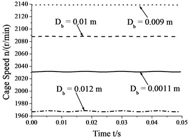
a) Cage speed vs. roller diameter
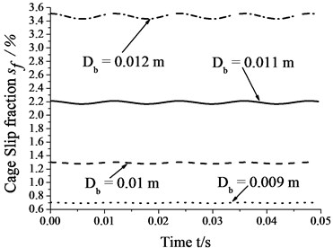
b) Cage slip fraction vs. roller diameter
4.5. Skidding analysis under different roller lengths
Fig. 9 shows that the amplitudes of cage speed and cage slip fraction increase as the roller length increases. In other words, the influence of whirl on bearing skid increases as the roller length increases. In contrast, the cage speed decrease as the roller length increases, whereas the cage slip fraction shows the reverse trend. Thus, one can decrease the degree of skid by suitably decreasing roller length.
Fig. 9Skidding analysis under different roller lengths (n= 5000 r/min; Fr= 500 N; e= 4.5e-5 m)
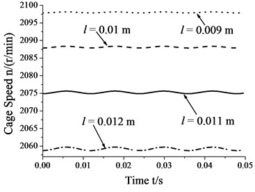
a) Cage speed vs. roller length
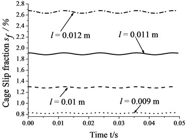
b) Cage slip fraction vs. roller length
4.6. Skidding analysis under different numbers of rollers
Fig. 10 shows that the amplitudes of cage speed and cage slip fraction increase as the number of rollers increases. In other words, the influence of whirl on bearing skid increases as number of rollers increases. In contrast, cage speed decreases as the number of rollers increases, whereas the cage slip fraction shows the reverse trend. Thus, one can reduce the degree of skid by suitably decreasing the number of rollers.
Fig. 10Skidding analysis in different number of rollers (n= 5000 r/min; Fr= 500 N; e= 4.5e-5 m)
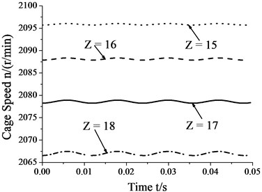
a) Cage speed vs. number of rollers
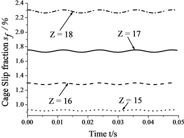
b) Cage slip fraction vs. number of rollers
4.7. Skidding analysis under different diametral clearance
Fig. 11 shows that the amplitudes of cage speed and cage slip fraction decrease as the diametral clearance increases. In other words, the influence of whirl on bearing skid decreases as the diametral clearance increases. In contrast, the cage speed increases as the diametral clearance increases, whereas the cage slip fraction shows the reverse trend. Thus, the degree of skid by suitably increasing the diametral clearance.
Fig. 11Skidding analysis under different diametral clearances (n= 5000 r/min; Fr= 500 N; e= 4.5e-5 m)
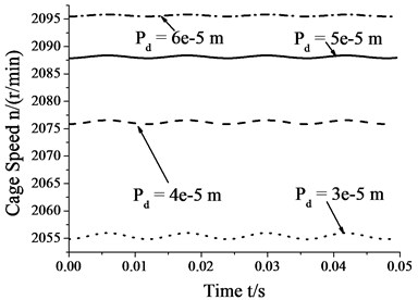
a) Cage speed vs. diametral clearance
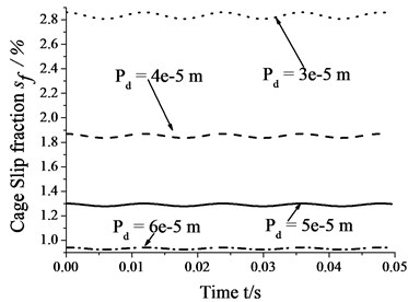
b) Cage slip fraction vs. diametral clearance
4.8. Discussion
The analysis results show that the values of cage speed and cage slip fraction vary with time because of whirl. Furthermore, whirl leads to the generation of additional forces in roller-cage and roller-ring pairs. These forces oscillate over time, which may affect bearing service life and stability. More importantly, the magnitudes of the roller-rings and roller-cage oil film forces oscillate as well. In real-life situation, oil film force is an important factor for resisting bearing skid, and its oscillation may increase the degree of bearing skid. As radial load and diametral clearance increase, the degree of skidding and the influence of whirl motion on bearing skid decrease. On the contrary, as the roller diameter, roller length, and number of rollers decrease, the degree of skidding and the influence of whirl motion on bearing skid decrease. The degree of skidding is directly correlated with the whirl radius. So in order to reduce skid and improve stability of roller bearing in practice, the whirl radius, roller diameter, roller length, and number of rollers should be decreased, whereas the radial load and diametral clearance should be increased moderately. It is observed that viscosity has both positive and negative effects on bearing skid. Therefore, it should be decided only after comprehensive situation-specific consideration for reducing the degree of skid.
A roller bearing is a complex nonlinear dynamic system. The accurate skidding mechanism of the roller in a HSRB considering bearing whirling is very difficult to obtain by experiment under current laboratory conditions. This study mainly focusses on the theoretical analysis, then the experimental investigation on skidding failure of HSRB considering bearing whirling is the focus of the future research.
5. Conclusions
In this manuscript, by treating the whirl orbit as circular, a skidding analysis model considering bearing whirl was developed. Then, the skidding mechanism was investigated systematically considering various factors such as whirl orbit, radial load, lubricating oil viscosity, diametral clearance, roller diameter, roller length, and number of rollers.
(1) Cage speed and cage slip fraction are unstable because of whirl, and their values vary with time, which leads to an increase in the degree of skid.
(2) The degree of skid varies directly as the whirl radius.
(3) The degree of skid decreases and whirl motion has a smaller influence on bearing skid as the radial load and diametral clearance increase.
(4) The degree of skid decreases and whirl motion has a smaller influence on bearing skid as the roller diameter, roller length, and number of rollers decrease.
(5) The degree of skid decreases as the viscosity decreases. However, the amplitude of cage slip fraction increases with a decrease in viscosity. The result shows that viscosity has both positive and negative effects on bearing skid.
Therefore, for improving HSRB service life and stability, the whirl radius, roller diameter, roller length, and number of rollers should be decreased, whereas the radial load and diametral clearance should be increased moderately. Concurrently, the factors that may lead to excessive bearing vibration should be diminished as soon as possible. The authors hope that the results of this study could be helpful for supporting the failure mechanism and vibration analysis of high-speed precision rolling bearings in the future.
References
-
Tassone B. A. Roller bearing slip and skidding damage. Journal of Aircraft, Vol. 12, Issue 4, 1975, p. 281-287.
-
Dowson D., Higginson G. R. Theory of roller bearing lubrication and deformation. Proceedings of Convention on Lubrication and Wear, Institution of Mechanical Engineers, London, 1963, p. 216-227.
-
Harris T. A. An analytical method to predict skidding in high speed roller bearings. ASLE Transactions, Vol. 9, Issue 3, 1966, p. 229-241.
-
Harris T. A., Kotzalas M. N. Rolling bearing analysis: advanced concepts of bearing technology. Wiley, New York, 2007.
-
Hamrock B. J., Jacobson B. O. Elastohydrodynamic lubrication of line contacts. ASLE Transactions, Vol. 27, Issue 4, 1984, p. 275-287.
-
Ghaisas N., Wassgren C. R., Sadeghi F. A. Cage instabilities in cylindrical roller bearing. Journal of Tribology, Vol. 126, Issue 4, 2004, p. 681-689.
-
Mukhopadhyay G., Bhattacharya S. Failure analysis of a cylindrical roller bearing from a rolling mill. Journal of Failure Analysis and Prevention, Vol. 11, Issue 4, 2011, p. 337-343.
-
Tu W. B., Shao Y. M., Mechefske C. K. an analytical model to investigate skidding in rolling element bearings during acceleration. Journal of Mechanical Science and Technology, Vol. 26, Issue 48, 2012, p. 2451-2458.
-
Zhang L. B. Skidding analysis of cylindrical roller bearing. Master Thesis of Xi’an Jiaotong University, Xi’an, 2009, (in Chinese).
-
Chen W., Li J. N. Skidding analysis of high speed rolling bearing considering whirling of bearing. Journal of Mechanical Engineering, Vol. 49, Issue 6, 2013, p. 38-43, (in Chinese).
-
Moraru L., Keith T. G., Dimofte F., et al. Dynamic modeling of a dual clearance squeeze film damper. Part II: Tribology transactions, Vol. 49, Issue 4, 2006, p. 611-620.
-
Delgado A., Andres L. S. Identification of force coefficients in a squeeze film damper with a mechanical seal: large contact force. Journal of Tribology, Vol. 132, Issue 3, 2010, p. 032201-032207.
-
Pietra L. D. Analytical and experimental investigation of squeeze-film dampers executing circular orbits. Meccanica, Vol. 35, Issue 2, 2000, p. 133-157.
-
Pietra L. D., Adiletta G. The squeeze film damper over four decades of investigations. Part I: Characteristics and operating features. Shock and Vibration, Vol. 34, Issue 1, 2002, p. 3-26.
-
Zhang J., Roberts J. B., Ellis J., et al. Experimental behavior of a short cylindrical squeeze film damper executing circular centered orbits. Journal of Tribology, Vol. 116, Issue 3, 1994, p. 528-534.
-
Defaye C., Arghir M., Bonneau O., et al. Experimental study of the radial and tangential forces in a whirling squeeze film damper. Tribology Transactions, Vol. 49, Issue 2, 2006.
About this article

