Abstract
A single mass vibration system driven by two counter-rotating motors is studied in this paper. The nonlinear factor of vibration spring in the vertical direction is considered. Based on the Lagrange Equations, the mechanic-electric coupling dynamic equation of the vibration system is established. The condition of the self-synchronization implementation of the system is obtained by using the Hamilton theory. Applying once approximate method of nonlinear system stability, the asymptotic stability condition of the vibration system at equilibrium point is deduced. They provide theoretical basis for the simulation of self-synchronization of vibration system.
1. Introduction
The earliest detailed accounts on synchronized motion was made by Huygens [1], who observed that two clock pendulums suspended from stiff wooden beams could run in a steady state and move in opposition to each other at the same angular velocity. Since 1894, the synchronous phenomena was also found in nonlinear circuits by scientists, such as Rayleigh [2] found that two organ tubes could produce a synchronized sound when the outlets were close to each other and Pol [3] observed the synchronization of certain electrical-mechanical system. They called this phenomenon as “frequency capture”, which was a unique phenomenon of nonlinear system. In the 1960s, Dr. Blekhman I. I. [4-6] in Soviet Union proposed the self-synchronization theory of vibrating machinery with double exciters and established the conditions of existence and stability of self-synchronization of the exciters in vibrating system based on the analytical method of direct motion separation. The method was applied later by some researchers Ragulskis K. M. [7-8], Khodzhaev K. Sh. [9], Sperling L. [1-11] and Nagaev R. F. [12] from Lithuania, Russia, Germany and other countries to a number of synchronization problems. It has been proven to be useful and descriptive leading to better understanding and theoretical explanation of the mechanism of self-synchronization. Japanese researchers Inoue J. and Araki Y. [13] et al. studied the multiple frequency self-synchronization of vibration machine driven by two motors. Chinese scholar Prof. Wen [14-16], selected the phase difference between two exciters as the variable to simplify the analytical method for establishing the conditions of existence and stability of self-synchronization of two identical exciters in a vibrating system. Later Balthazar J. M. [17] from Brail has also given some short comments on self-synchronization of two non-ideal sources. Yamapi R. [18-19] in Cameroon introduced dynamic characteristics of two motors to the self-synchronization theory. The self-synchronization of a vibrating system from the effect of electric-mechanic motors coupling was dependent on the dynamic parameters of two induction motors. In recent years, many scholars [20-22] considered nonlinear factor of vibration system and the vibration problems of nonlinear system were solved well.
In this paper, a single-mass nonlinear vibrating system driven by two counter-rotating motors is studied. The nonlinear factor of vibration spring in the vertical direction is considered. A mechanic-electric coupling dynamic model of the vibration system is established. The condition of self-synchronous operation implementation of the vibration system is obtained according to Hamilton principle. Based on once approximate method of stability of nonlinear system, the asymptotic stability condition of the vibration system at the equilibrium point is deduced. They provide theoretical basis for the simulation of self-synchronization of vibration system.
2. The mechanic-electric coupling dynamic model of the vibrating system
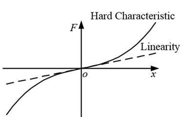
The mechanical model of a single-mass nonlinear vibrating system driven by two counter-rotating motors is presented in Fig. 1, which consists of a vibrating body and two eccentric rotors. The vibrating body is connected with fixed support by four springs in -axis and -axis directions, respectively. The hard characteristic of the springs in -axis direction is considered. Fig. 2 shows the hard characteristic curve. The expression of elastic force is described as Eq. (1):
Fig. 1The mechanical model of a single-mass nonlinear vibration system
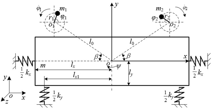
Fig. 2Hard characteristic curve of nonlinear spring
The two eccentric rotors driven by two induction motors separately are installed symmetrically about the plane which goes through the centroid of the vibrating body. and are separately the rotation centers of the two counter-rotating eccentric rotors.
As can be seen from Fig. 1, the vibrating body exhibits three degrees of freedom, i.e., two translation motions in the -axis and -axis directions and one swing in direction. In addition, the eccentric rotor 1 and 2 rotate about their own spindle and the rotor angle are separately denoted by and . Therefore, the vibrating system needs five independent coordinates to describe its special position, i.e., this vibrating system has five degrees of freedom.
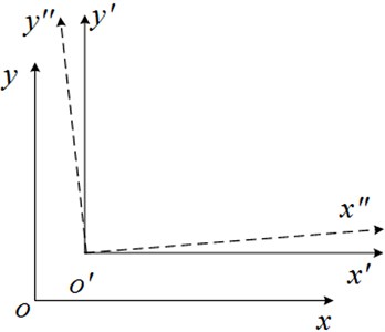
As illustrated in Fig. 3, three reference frames can be assigned as follows: the fixed coordinate system which is fixed to the inertial space; the translation coordinate system and the rotating coordinate system which are both fixed to the vibrating body. In the rotating coordinate system , the centroid coordinates of the eccentric rotor 1 and 2 can be expressed as:
where and are the rotation radius of the eccentric rotor 1 and 2, respectively; is the distance between the center of rotation of each eccentric rotor and the centroid of the vibration body; is the included angle between the linkage between the center of rotation of each eccentric rotor and the centroid of the vibration body and horizon -axis. and are separately the rotor angles of the eccentric rotor 1 and 2; is the rotation angle of the vibration body around the -axis rotation.
Fig. 3Coordinate systems: fixed-coordinate system oxy; translation coordinate system o'x'y'; rotating coordinate system o'x″y″
The kinetic energy of the vibrating system can be expressed as follows:
where is the mass of vibration body; and are the mass of exciter 1 and 2; is the moment of inertia of vibration body; and are the moments of inertia of motor 1 and 2.
The vibrating body is connected with fixed base by four springs in -axis and -axis directions, respectively. When the vibration system is working, the deformations of springs , , and are expressed as:
Then the potential energy of the system can be expressed as:
where and are the stiffness coefficient of spring and , ; and are the stiffness coefficient of spring and , ; is the stiffness coefficient of nonlinear spring, which can be obtained by experimental curve of spring; is the nonlinear function in -axis direction, .
Then the viscous dissipation function of the system can be described as the following:
where , , and are the damping coefficient of spring , , and , respectively.
The Lagrange’s equation is expressed as:
where is the generalized coordinate of the system; is the generalized force of the system. is chosen as the generalized coordinates of the vibrating system and the generalized forces are: , and ; and are the electromagnetic torque of motor 1 and 2; and are the damping coefficient of motor 1 and 2.
Substitute Eqs. (3), (5) and (6) to Eq. (7) and the electromechanical-coupled dynamic model of the system can be reduced as follows:
where is the mass of vibration system, ; is the moments of inertia of the vibration system, and are the stiffness coefficients of the vibration system in , and directions, and ; and are the damping coefficients of the vibration system in , and directions, and ; denotes .
According to the electromagnetic property of asynchronous motor [23], the relationship between electromagnetic torque and speed is deduced as Eq. (9):
where is the maximum torque; is the critical slip, ; is the overload coefficient; is the rated torque; is the rated slip; is the rated speed; is the speed of motor at any time.
3. The condition of self-synchronization implementation
We assume that the average phase of two eccentric rotors is , and , where is the average angular velocity. The phase difference between the two eccentric rotors is , i.e.:
Then the phase of the eccentric rotor 1 and 2 are separately described as:
In the first three formulas of Eq. (8), the angle accelerations , of the eccentric rotor 1 and 2 are so small that they could be neglected. In actual project, . Therefore, the first three formulas of the electromechanical coupling dynamic equation Eq. (8) can be simplified as Eq. (12):
Introduce the following parameters:
where , and are the natural frequency of the vibration system in , and directions; , and are the damping ratios of the vibration system in , and directions.
For Eq. (12), the vibration response in each direction can be solved by gradual method of nonlinear system. When the system is working in the non-resonant case, the meaningful solution for project can be expressed as:
where the vibration amplitude, the lagging phase angle in each direction are separately:
in which the equivalent natural frequency and the equivalent damping ratio in direction are:
In one vibration period, Hamilton actions can be expressed as:
According to Eq. (14), , , , , and can be deduced. According to Eq. (2), , , and are obtained. Substitute them to the kinetic energy Eq. (3) and potential energy Eq. (5). Compared with , and , is so small that it could be neglected. Do an integral over the kinetic energy and potential energy within 0~2 and substitute the integral value into Eq. (17). Then Eq. (17) can be expressed as follows:
Expand and in Eq. (18) and merger the similar items which contain , and constant terms. Then Eq. (18) can be rewritten as:
where:
The Hamilton’s principle is described as Eq. (21):
Substitute (19) into (21) and arrange to obtain:
In Eq. (22), define , and as the frequency capture moment, the self-synchronization coefficient and the stability coefficient. They can be expressed as follows:
According to the above deduction, two eccentric rotors should have a constant phase difference in order to implement self-synchronous operation. Then we have Eq. (24):
Substitute Eq. (23) into Eq. (24) and the condition of implementing synchronization can be deduced, which is that the frequency capture torque of two motors is greater than or equal to the torque difference between the residual electromagnetic torques of two motors.
When , satisfied the following two ranges:
(1) When , i.e., , , i.e., the phase difference is in range.
(2) When , i.e., , , i.e., the phase difference is in range.
4. The stability of self-synchronization motion
In the last two formula of Eq. (8), the swinging angular velocity is so small that it can be able to be neglected. Compared with and , is very small and can be ignored. Then the last two formula of Eq. (8) can be simplified as:
We assume:
Then we can obtain:
According to Eq. (14) and Eq. (15), we can obtain , and . Substitute them into Eq. (27) and neglect the higher order terms, then we have:
where:
The corresponding equilibrium point equation with Eq. (28) can be expressed as Eq. (30):
According to Eq. (30), when:
The equilibrium point of the vibration system is obtained as . As can be seen from the equilibrium point and Eq. (26), when the system is stable at this point, it can implement self-synchronization operation of zero angular velocity difference. The phase plane singularity at the equilibrium point of Eq. (30) is analyzed and the characteristic equation of Eq. (30) is obtained as the following:
where is the phase difference of two motors at the equilibrium point of the system. Based on the once approximate method of stability of nonlinear system, when:
The vibrating system have asymptotically stable focus on the phase plane and the focus is the equilibrium point of nonlinear vibrating system at the time of non-resonant.
Substitute the phase difference of two motors at the equilibrium point of the system to Eq. (33) and neglect the higher order term. The condition of gradual stability when the vibration system operate synchronously at equilibrium point can be deduced:
5. Conclusions
A single mass vibration system driven by two counter-rotating motors is studied in this paper. The hard characteristics of vibration springs in the vertical direction is considered and based on the Lagrange Equations, the mechanic-electric coupling dynamic equation of the vibration system is established. When the system is working in the non-resonant case, the meaningful solutions for project in horizon, vertical and swing directions are obtained by gradual method of nonlinear system.
By the Hamilton theory, the condition of the self-synchronization implementation of the system was obtained, which is that the frequency capture moment of two motors is greater than the absolute value of the output electromagnetic torque difference, i.e., . According to Eq. (24), when 1, satisfied the following two ranges: when , i.e., –1, , i.e., the phase difference 2 is in range. When , i.e., 1, , i.e., the phase difference 2 is in range.
Applying once approximate method of stability of nonlinear system, the asymptotic stability condition of the vibration system at equilibrium point are deduced, which can be expressed as the following:
References
-
Huygens C. Horologium oscilalorium. Paris, Frence, 1673.
-
Rayleigh J. Theory of sound. Dover, New York, 1945.
-
Vander Pol B. Theory of the amplitude of free and forced triode vibration. Radio Rev., Vol. 1, 1920, p. 701-710.
-
Blekhman I. I. Self-synchronization of vibrators in some types of vibrational machines. Inzhenerny Sbornik, Vol. 16, 1953, p. 49-72, (in Russian).
-
Blekhman I. I., Fradkov A. L., Nijmeijier H., et al. On self-synchronization and controlled synchronization. System & Control Le, 1997, p. 299-305.
-
Bleckman I. I., Fradkov A. L., Tomchina O. P., et al. Self-synchronization and controlled synchronization: general definition and example design. Mathematics and Computers in Simulation, Vol. 58, 2002, p. 367-384.
-
Ragulskis K. M. Mechanisms on the vibrating base. Acad. of Sciences of Lithuanian SSR, 1963, p. 232, (in Russian).
-
Ragulskis K. M., Vitkus I. I., Ragulskiene V. L. Self-synchronization of systems. Self-synchronous and vibro-shock systems. Mintis, Vilnius, 1965, p. 186, (in Russian).
-
Khodzhaev K. Sh. Synchronization of the mechanical vibrators related to the linear oscillatory system. Izv. AN SSSR, MTT, Vol. 4, 1967, p. 14-24, (in Russian).
-
Sperling L. Self-synchronization static and dynamic imbalanced vibrators. Part I: Bases. Technical Mechanics, Vol. 14, Issue 1, 1994, p. 61-76, (in German).
-
Sperling L. Self-synchronization static and dynamic imbalanced vibrators. Part II: Execution and Examples. Technical Mechanics, Vol. 14, Issue 2, 1994, p. 85-96, (in German).
-
Nagaev R. F. Dynamics of synchronizing systems. Berlin, Heidelberg, Spriger, 2003, p. 326.
-
Inoue J., Araki Y., Miyaura S. Self-synchronization of mechanical system (multiple cycle). Proceedings of Japanese Mechanical Engineering Society, Vol. 42, Issue 353, 1951, p. 103-110, (in Japanese).
-
Wen Bangchun Some new results to research on vibration synchronization theory with its application. Journal of Vibration and Shock, Vol. 3, 1983, p. 1-10.
-
Wen Bangchun, Guan Lizhang Research concerning the theory of synchronization on a self-synchronous vibrating machine with single and dual mass in space motion. Northeast. Univ., Nat. Sci., Vol. 19, 1980, p. 54-63.
-
Wen Bangchun, Zhao Chunyu, Fan Jian The application and development of synchronization theory in mechanical system. Journal of Vibration Engineering, Vol. 3, 1997, p. 264-272.
-
Balthazar J. M., Palacios Felix J. L., Brasil R. F. Short comments on self-synchronization of two non-ideal sources supported by a flexible portal frame structure. Journal of Vibration and Control, Vol. 10, 2004, p. 1739-1748.
-
Yamapi R., Woafo P. Dynamics and synchronization of coupled self-sustained electromechanical devices. Journal of Sound and Vibration, Vol. 5, 2005, p. 1151-1170.
-
Yamapi R., Woafo P. Synchronized states in a ring of four mutually coupled self-sustained electromechanical devices. Communications in Nonlinear Science and Numerical Simulation, Vol. 11, 2006, p. 186-202.
-
Li Xiaohao, Liu Jie, Liu Jintao Analysis of the frequency catching sharp resonance synchronization theory of nonlinear vibration machine. Advanced Scientific Publishers, Vol. 4, 2011, p. 1842-1846.
-
Bayıroğlu H., Alışverişçi G. F., Ünal G. Nonlinear response of vibrational conveyers with nonideal vibration exciter: superharmonic and subharmonic resonance. Mathematical Problems in Engineering, Vol. 2012, 2012, p. 1-12.
-
Warminski J., Balthazar J. M., Brasil R. M. L. R. F. Vibrations of a non-ideal parametrically and self-excited model. Journal of Sound and Vibration, Vol. 245, 2001, p. 363-374.
-
Xie Lirong, Wang Zhiyong, Chao Qin Research on the mechanical characteristic of squierrelcage asynchronous motors. Proceedings of the CSEE, Vol. 28, Issue 21, 2008, p. 68-72, (in Chinese).
About this article

This work is supported by National Science Foundation of China (Grant No. 51175071 and No. 51375080) and the Fundamental Research Funds for the Central Universities (Grant No. N120203001).
