Abstract
Shaft orbit is a significant diagnosis criterion, and its identification plays an important role in the fault diagnosis of large rotating machinery. The main difficulty of shaft orbit identification is how to extract the shape features automatically and effectively. Therefore, in this paper, a novel method named statistical fuzzy vector chain code (SFVCC) is proposed for the feature extraction of shaft orbit, which has such advantages as invariance, simple calculation and high separability. Furthermore, taking the extracted feature vectors as input, support vector machine (SVM) is utilized to identify various kinds of shaft orbits for rotating machinery. Comparative experiments are implemented, the results reveal that, compared with previous methods, the proposed method can identify the shaft orbit more effectively and efficiently with satisfactory accuracy.
1. Introduction
Large rotating machinery is the essential part of many industrial applications, and its health condition is directly related to the safety and efficiency of industrial production. Hence, the corresponding fault diagnosis has crucial significance, which needs to detect the fault type and assess the fault level as early as possible. As the main part of fault diagnosis, vibration fault diagnosis has been the subject of extensive researches [1-4]. During the last decades, shaft orbit has been used as an important criterion to identify different faults, since it contains abundant information revealing the running state and fault condition of the rotating machinery [3, 4]. Especially, the shape of shaft orbit reflects various fault information, such as misalignment, unbalance, and oil whip, and it is a crucial basis for fault diagnosis to identify the shaft orbit by its shape feature.
Although the shape of shaft orbit can be easily identified by human’s brain, it is still difficult to carry out the identification automatically by computer with satisfactory accuracy. The most essential problem of the shaft orbit identification is feature extraction, and the separability of the extracted shape feature determines the identification accuracy. In recent years, plenty of studies have been fully developed for shape feature extraction [5-17], such as geometric characteristics, FFT, Wavelet Transform (WT), invariant moments, Fourier descriptor (FD), Walsh descriptor (WD) and chain code. All of them can represent the shaft orbit to some extent.
The geometric characteristics including rectangularity, circularity, eccentricity and shapeparameter, can extract the schematic shape feature of shaft orbit simply, but more detailed information is abandoned by only using these characteristics. Therefore, they are usually combined with other features to represent the shape with higher separability. FFT and WT are region-based methods [5-8], which represent the shape in terms of the internal characteristics, and both of them have their own advantages and disadvantages. The 2-D FFT is a traditional signal image processing method, which transforms the original shaft orbit into frequency domain image [6], however, it could not reveal the signal instantaneous mutation and image edge. As a time-frequency domain signal analysis method, WT can be used to represent the shaft orbit with different scales, and that overcomes the shortcomings of FFT and makes it available to detail transaction and edge detection [7, 8]. But its complicated calculation and the large amount of extracted features could lead to great computational burden and high time consuming. Invariant moments are proposed by HU [9] and improved by Chen [10] to extract the shape feature with invariance to scaling, translation and rotation by combining the normalized 2- and 3-order central moments through some different algebraic manipulations, but the physical meaning of the acquired invariant moments is spoiled during the manipulation process [11], and that makes it difficult to guarantee the identification accuracy of shaft orbit.
FD, WD and chain code are all contour-based methods, and they only utilize the boundary characteristics to represent the shaft orbit. FD [12, 13] reduces the 2-D problem to 1-D by using the center distance to substitute the coordinate of boundary pixels, and takes the FFT spectrum of the center distance sequence as the shape features. Xiang [14, 15] uses Walsh descriptor to extract shape feature, which takes the fast WalshTransform instead of FFT to deduce the descriptor. In both FD and WD, the feature amount of the whole spectrum is so large that only a part of the spectrum can be selected as the descriptors, and the representation abilities of them both depend on the descriptor selection. Chain code is an effective method for shape recognition and shows the advantages of simple calculation and small storage space [16], but still has some problems with the sampling grid spacing [17].
To overcome the defects of previous methods, in this paper, a novel feature extraction method named statistical fuzzy vector chain code (SFVCC) based on the chain code is proposed, which focuses on the rotating direction and angle information, and introduces fuzzy vectors to construct the chain code instead of the conventional shape codes. It inherits the advantages of the chain code, and avoids the sampling grid spacing, so that it can represent the shape characteristics with high separability. Furthermore, taking these extracted feature vectors as input, support vector machine (SVM) is utilized to process the shaft orbit identification automatically. SVM is a relatively new supervised learning technique available for pattern recognition problems [18], which has been successfully applied to many different fields such as fault diagnosis.
The rest of the paper is organized as follows: In Section 2, angle information of shaft orbit is described. In Section 3, shaft orbit feature extraction and representation by SFVCC is illustrated. In Section 4, the shaft orbit feature vectors is trained and tested by SVM. Section 5 gives the experimental results and discussion. And the conclusions of this work are summarized in Section 6.
2. Angle information of shaft orbit
The shaft orbit of rotating machinery can be synthesized by the vibration signals in both and directions collected by two orthogonal displacement sensors installed on each bearing section. However, the vibration signals are usually accompanied with noise, and the purification procedure is important and necessary to eliminate the noise and improve the signal quality before the feature extraction [19, 20].
Fig. 1Internal angles of the polygon
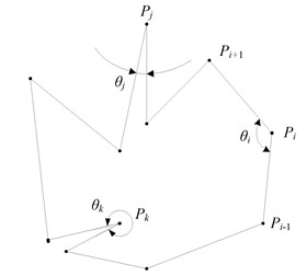
The purified shaft orbit is actuallya complex directed polygon [21], and the goal of feature extraction is to represent the shape characteristics of the polygon with high separability. Since the shape information is fully contained by its angle information and rotating direction, it is feasible to extract the shape features by calculating the internal angles of all vertices, and a simplified example of internal angle calculation is given in Fig. 1, where is the thvertex, while is the corresponding internal angle. The calculation of uses the following steps.
Step 1. Translation.
Suppose the coordinates of vertex is (), then move the polygon graphic on -plane, so that the translated vertex coincides with the origin of coordinates (0, 0), while the vertices and are translated to and , and their coordinates can be obtained by the following equations:
Step 2. Rotation.
Rotate vertex in clockwise direction around until it reaches the directed edge , and the rotating angle can be deduced from Eq. (2):
where and are the length of the edge and [21].
Step 3. Correction.
By repeating the above two steps, the rotating angles of all vertices can be obtained, and it is noticed that, the relation between internal angles and rotating angles depends on the moving direction of the polygon. If the moving direction is counter-clockwise, the internal angle equals , otherwise, equals . In order to decide the moving direction of the polygon, the rotating angle of a special vertex with the minimum -coordinate value is utilized as a criterion. It has been proved that the internal angle of must be less than [22], and the internal angle can be obtained by Eq. (3):
All the internal angles can be deduced by the three steps, furthermore, the concavity and convexity of each vertex can be identified by its corresponding internal angle, and the convexity rate defined as the quotient of the convex vertex amount divided by total vertex amount, can be obtained and utilized as an extracted feature. All of these characteristics can be used to represent the shape features of shaft orbit.
3. Shaft orbit representation by statistical fuzzy vector chain code
As the amount of vertices is quite large, and the internal angles distribute in the range of rad randomly, the set of internal angles and convexity rate is too complex to be used as the shape feature vectors directly. Therefore, it’s necessary to extract more effective feature vectors from the angle information. As the angle information manifests as a sequence of internal angles, the ideas of chain code can be utilized, and a novel method, statistical fuzzy vector chain code, is proposed and used to extract feature vectors.
3.1. Theory of chain code
Conventional Freeman chain code represents a shape contour by a starting point and connected sequence of straight-line segments of specified length and direction [17], defined as:
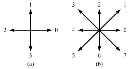
where denotes the coordinate of the selected starting point, (1, 2, 3,..., ) is the directional code deduced by the length and direction of the segment from the th pixel to its neighbor, and 4 or 8, respectively for the 4- or 8-directional chain code, as shown in Fig. 2(a) and (b). The polygon is coded from the starting point along the contour in a determined direction, and it will return to the starting point when the contour is closed. More details of chain code can be found in [23, 24].
Fig. 2Direction numbers
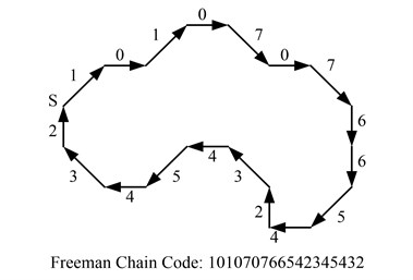
An example of a polygon and its 8-directional chain code is given in Fig. 3, and each pixel on the contour is coded by an integer from 0 to 7, respectively corresponding to the eight directions: right, upper right, upper, upper left, left, and so on.
Fig. 3Example of chain code
3.2. Statistical fuzzy vector chain code (SFVCC)
In freeman chain code, before the contour coding, the polygon needs to be rasterized to obtain the sequence of contour pixels, and unsuitable spacing of the sampling grid may impair the representation capability of chain code. To overcome this short-coming, statistical fuzzy vector chain code (SFVCC) is proposed.
SFVCC focuses on the angle information and rotating direction, and utilizes the internal angles to code the shape contour, so that, the feature extraction can be implemented without rasterization by just using the sequence of sampling vibration signals, and the decrease of representation capability caused by sampling grid spacing can be avoided. Meanwhile, to improve the separability of representation, fuzzy theory is introduced to deduce the chain code from the angle information, which has been widely applied to pattern recognition [25, 26].
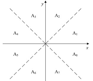
All the internal angles are supposed to be in the range of rad, which is divided into eight subspaces , as is shown in Fig. 4(a), respectively correspond to [), [),…, [) and []. The internal angles are located into the eight subspaces by fuzzy recognition, and the triangle fuzzy functions are chosen to calculate the membership to all subspaces, as shown in Fig. 4(b). The fuzzy vector code (FVC) of the vertex is defined as follow:
where is the length of , and is the membership vector constructed by the fuzzy membership of ( 1, 2,…,8). The shape contour is coded by the acquired FVCs, and furthermore, the FVCs are used to replace the conventional 8-directional code and compose the fuzzy vector chain code (FVCC):
Fig. 4Fuzzy vector code: a) subspace division; b) fuzzy functions
a)
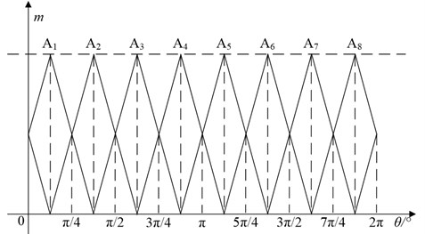
b)
One advantage of using the angle information is that, the internal angles keep invariant no matter how the shape is scaled, translated or rotated. Thus, the FVCC is invariant to scaling, translation, and rotation, but it is perceived that the FVCC may change with the starting point selection. To overcome this defect, the statistical fuzzy vector chain code (SFVCC) is proposed, which extracts the statistical information of the FVCC to represent the shape characteristics of shaft orbit. Meanwhile, these statistical features are combined with the convexity rate to improve the representation capability, and the SFVCC is defined as:
where is the circumference of the shape, which can be approximately deduced by summing the length of all the segments , is the convexity rate, SUM(FVCC) is the sum vector of all the fuzzy vector codes and is the statistical fuzzy membership to the th subspace () defined as:
It can be noticed that, the statistical features of FVCC represent the shaft orbit by the specific fuzzy memberships of all the internal angles to each subspace in a microscopic way, while the convexity rate reveals the amount of the convex vertices and represents the shape in a macroscopic way. By combining them together, the shape characteristics of the shaft orbit can be represented comprehensively. Obviously, SFVCC is not only invariant to scaling, rotation and translation, but also invariant to the starting point selection.
3.3. Shaft orbit feature vector extraction
Based on the theories above, the feature extraction of shaft orbit from the acquired vibration signals can be described as a sequence of operations including purification, normalization, angle calculation and SFVCC computation, and in the process of normalization, the sequences of vibration signals are separately normalized to the range of 0-1 by linear transformations. The shaft orbit feature vector extraction uses following steps:
Step 1: Acquire the vibration signals in both and direction, and purify them.
Step 2: Normalize the vibration signals, and synthesis the shaft orbit.
Step 3: Use the coordinates of the shaft orbit to calculate the internal angles of the polygon according to Eq. (1) to (3), and identify the concavity-convexity of each vertex.
Step 4: Compute the fuzzy vector chain code using Eq. (5) and (6) based on the internal angles.
Step 5: Compute the SFVCC using Eq. (7) and (8), and get the shaft orbit feature vectors.
Fig. 5Representation of shaft orbit: a) original signal; b) statistical fuzzy vector chain code
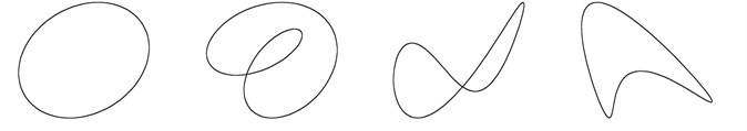
a)

b)
Generally, there are four typical kinds of shaft orbit: ellipse, inner “8”, outer “8” and banana, corresponding to three common faults: unbalance, oil whip and misalignment. Four different original shaft orbits are shown in Fig. 5(a), and their SFVCCs are listed in Fig. 5(b). It can be seen that, the SFVCC of different shaft orbit is unique, and quite different from each other. Thus, it can be utilized for feature extraction in this work, and the identification problem can be solved.
4. Shaft orbit identification using SVM
To identify the shape of shaft orbit by its shape feature is actually a pattern recognition problem, in which an accurate and efficient classification approach is quite essential, while the support vector machine is an effective classification method with strong robustness, simple structure, high recognition accuracy and computational efficiency [27]. Therefore, in this section, the extracted feature vectors will be used to train SVM and make it an identifier for shaft orbit identification.
SVM is based on structural risk minimization, and it maps the input vectors on to a high-dimensional space and constructs an optimal separating hyper-plane simply relying on the support vectors to achieve classification, which are the training examples closest to the optimal separating hyper-plane, and that makes SVM a more effective and efficient identifier [28, 29].
Given a set of training samples: , the amount of the training samples is , the input vector , and the label , where is the dimension of the input vector. For the linearly separable case, the training samples can be divided into two parts by a separating hyper-plane, and the corresponding hyper-plane can be expressed by the following equation:
where the coefficient vector , and denotes the inner product of and . There could be a set of hyper-planes, and the purpose of SVM is to find the maximal margin hyper-plane. That can achieve maximum separation between the classes and minimize the expected generalization error. Meanwhile the hyper-plane should satisfy the following constraint:
Intuitively, it is an optimization problem to maximize the margin of the separating hyper-plane, which can be deduced as , and it can be converted into its dual problem:
where are the Lagrange multiplier, and Then the optimized are used to constitute the separating hyper-plane:
If the classification problem is linear non-separable, the input vectors x will be mapped on to a high-dimensional space by kernel function and different kernel functions can be selected to acquire the optimal results for different problems. In this paper, SVM is utilized to identify the shaft orbit, and more details of SVM can be found in [27-29].
5. Experimental study and analysis
The flowchart of the presented shaft orbit identification method is given in Fig. 6, and as mentioned above, the shaft orbit is represented by SFVCC and identified by SVM. Based on the above theory, this section identifies shaft orbit experimentally, and the simulative data samples of shaft orbits are constructed by the following formula:
where is the rotating angular velocity, and are respectively the vibration amplitude of the fundamental and second harmonic generation in and direction, , and , are their initial phase angle. Different shapes of shaft orbit can be obtained by changing the values of these parameters.
Fig. 6Flowchart of the presented shaft orbit identification method
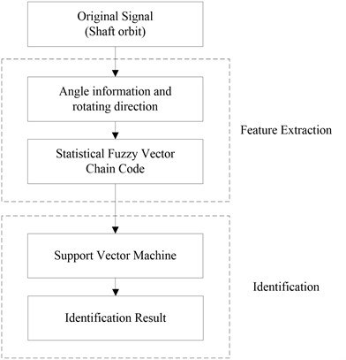
Fig. 7The general structure of the shaft orbit measurement system
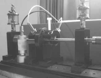
a) Rotor test device
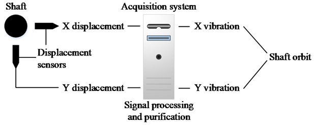
b) Shaft orbit measurement system
Fig. 7(a) gives the photo of the rotor test device, and Fig. 7(b) illustrates the general structure of its shaft orbit measurement system. In the measurement system of the rotor test device, a pair of eddy current displacement sensors are installed perpendicularly on the shaft near the rotor, by which the displacement signals of both and direction can be obtained. Then the acquisition system collects the displacement signals by equal periodic sampling, and the sampling frequency is set to 128 points per period. After processing and purification, the purified vibration signals can be deduced and synthesize the shaft orbit.
All of the experiments are implemented in PC with Intel Core i5 2.7 GHz CPU and 2G RAM using VC++ 2010 compiler and Matlab2010a simulation software based on Windows 7 operating system with the help of LIBSVM [30].
5.1. Identification experiment of shaft orbit
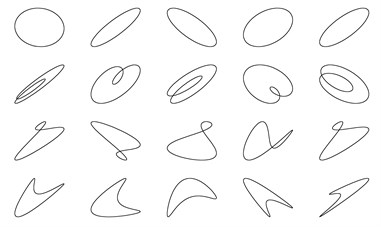
In the identification experiment, four typical classes of shaft orbits: ellipse, inner “8”, outer “8” and banana are included, and each class has 40 groups of original data collected by simulation. All the shaft orbits are divided into two parts randomly: half of them are training samples and used to train SVM, while the rest of them are testing samples and used to test the identification ability of the trained SVM. Part of the training and testing samples are respectively shown in Figs. 8, 9.
Firstly, the feature vectors of the training data are extracted by SFVCC described in the third part of the paper, and taken as input data , while the class numbers are taken as label . Then, several optimal hyper-planes separating the four classes are constructed, and the SVM is trained to become an identifier. In the process of identification, the feature vectors of testing data are extracted and imported to the SVM, and through the optimal separating hyper-planes, all of the testing data can be classified into the four classes, and the corresponding faults can be determined.
Table 1Feature vectors of the testing samples
ID | Shape | Feature vector | ||||||||
1 | Ellipse | 0.000 | 0.000 | 0.000 | 0.577 | 0.423 | 0.000 | 0.000 | 0.000 | 1.000 |
2 | Ellipse | 0.000 | 0.000 | 0.000 | 0.564 | 0.436 | 0.000 | 0.000 | 0.000 | 1.000 |
3 | Ellipse | 0.000 | 0.000 | 0.000 | 0.554 | 0.446 | 0.000 | 0.000 | 0.000 | 1.000 |
4 | Ellipse | 0.000 | 0.000 | 0.000 | 0.580 | 0.420 | 0.000 | 0.000 | 0.000 | 1.000 |
5 | Ellipse | 0.000 | 0.000 | 0.000 | 0.563 | 0.437 | 0.000 | 0.000 | 0.000 | 1.000 |
6 | Inner “8” | 0.000 | 0.000 | 0.002 | 0.605 | 0.393 | 0.000 | 0.000 | 0.000 | 1.000 |
7 | Inner “8” | 0.000 | 0.000 | 0.001 | 0.631 | 0.368 | 0.000 | 0.000 | 0.000 | 1.000 |
8 | Inner “8” | 0.000 | 0.000 | 0.002 | 0.608 | 0.390 | 0.000 | 0.000 | 0.000 | 1.000 |
9 | Inner “8” | 0.000 | 0.000 | 0.000 | 0.643 | 0.357 | 0.000 | 0.000 | 0.000 | 1.000 |
10 | Inner “8” | 0.000 | 0.000 | 0.003 | 0.597 | 0.400 | 0.000 | 0.000 | 0.000 | 1.000 |
11 | Outer “8” | 0.000 | 0.000 | 0.002 | 0.516 | 0.481 | 0.001 | 0.000 | 0.000 | 0.550 |
12 | Outer “8” | 0.000 | 0.000 | 0.000 | 0.520 | 0.479 | 0.001 | 0.000 | 0.000 | 0.580 |
13 | Outer “8” | 0.000 | 0.000 | 0.002 | 0.473 | 0.525 | 0.000 | 0.000 | 0.000 | 0.450 |
14 | Outer “8” | 0.000 | 0.000 | 0.004 | 0.509 | 0.485 | 0.002 | 0.000 | 0.000 | 0.550 |
15 | Outer “8” | 0.000 | 0.000 | 0.002 | 0.514 | 0.482 | 0.002 | 0.000 | 0.000 | 0.550 |
16 | Banana | 0.000 | 0.000 | 0.006 | 0.505 | 0.488 | 0.001 | 0.000 | 0.000 | 0.710 |
17 | Banana | 0.000 | 0.001 | 0.003 | 0.521 | 0.475 | 0.000 | 0.000 | 0.000 | 0.690 |
18 | Banana | 0.001 | 0.001 | 0.002 | 0.502 | 0.492 | 0.002 | 0.000 | 0.000 | 0.700 |
19 | Banana | 0.000 | 0.000 | 0.003 | 0.536 | 0.461 | 0.000 | 0.000 | 0.000 | 0.660 |
20 | Banana | 0.000 | 0.001 | 0.005 | 0.506 | 0.487 | 0.001 | 0.000 | 0.000 | 0.730 |
Table 1 lists the extracted feature vectors of the testing samples shown in Fig. 8, where are the statistical features of the fuzzy vector chain code, and is the convexity rate. It is revealed that, all the shaft orbits of the same class have similar feature vectors. Meanwhile, the statistical features of ellipse and inner “8” are quite different from other classes, and by only using , they can be identified well, while the outer “8” and banana are hard to separate, since the difference between their statistical features is not obvious. But by combining them with the convexity rate, the features vectors of all the four classes are quite different from each other, and that guarantees the separability of the extracted shape features.
Fig. 8Partial training samples of experiment
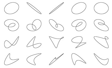
Fig. 9Partial testing samples of experiment
The results of identification are stated in Table 2, 100, 95.5, 93.5 and 100 % identification rates for ellipse, inner “8”, outer “8” and banana, and respectively corresponding to the fault unbalance, oil whirl and misalignment. The lowest identification rate of testing samples, 93.5 % for outer “8”, is also considerable, and it reveals that the proposed method shows not only high accuracy, but also satisfactory stability.
Table 2Identification rate of shaft orbit.
Shaft orbit | Fault case | Identification rate (%) |
Ellipse | Unbalance | 100 |
Inner “8” | Oil whirl | 95.5 |
Outer “8” | Misalignment | 93.5 |
Banana | Misalignment | 100 |
5.2. Comparative experiment of shaft orbit identification
To demonstrate the effectiveness of the proposed method, comparative experiments are implemented, in which the same data are utilized, and the shape features are extracted respectively by SFVCC and the previous methods including invariant moments, Fourier descriptor and Walsh descriptor. The experimental result demonstrates that SFVCC shows superiority in both accuracy and efficiency.
As is shown in Table 3, the numbers of features in the four method are respectively 9, 20, 20, 6, and the average results are 97.25, 88.25, 76.25, 58.75 % identification rates, 23.18, 34.09, 31.36, 2030 ms feature extraction time, and 17.42, 26.03, 25.81, 38.72 ms classification time respectively for SFVCC, Fourier descriptor, Walsh descriptor and invariant moments.
Table 3Comparison with different methods
Method | Number of features | Identification rate | Feature extraction time | Classification time |
SFCC | 9 | 97.25 % | 25.13 ms | 26.32 ms |
FD | 20 | 88.25 % | 34.09 ms | 29.75 ms |
WD | 20 | 76.25 % | 31.36 ms | 28.81 ms |
IM | 6 | 58.75 % | 2030 ms | 25.77 ms |
In the comparison results, the identification rate of invariant moments is the lowest, while its time cost of feature extraction is far more than the others. Firstly, in order to calculate the invariant moments the shaft orbit is rasterized and extracted as a matrix, and the amount of data is much larger than the shaft orbit counter. Thus the computational complexity is much higher. Secondly, invariant moments are deduced from the internal characteristics, by which ellipse can be recognized from other shapes, but the other shapes especially inner “8” can be hardly distinguished, and that reduces the average identification rate. Fourier descriptor and Walsh descriptor represent the shape counter respectively by two different mathematical transformations, and they have higher identification rate than invariant moments, and less time cost consuming of feature extraction. The time cost of classification depends on the number of features, and the method with more features consumes more time. Thus, in Fourier descriptor and Walsh descriptor, only the first 20 points of the whole spectrum are utilized as feature vectors, and that may reduce their identification rate. In conclusion, the proposed SFVCC shows highest identification rate withthe lowest time consuming, and its superiority in the shaft orbit identification is demonstrated.
6. Conclusion
In this paper, a novel method based on statistical fuzzy vector chain code and SVM to identify the shaft orbit for rotating machinery is proposed and illustrated, in which the shape feature vectors of shaft orbit is extracted by statistical fuzzy vector chain code, and identified by SVM automatically.
The identification results for four kinds of shaft orbit were presented of identification rate, and compared to three previous feature extraction algorithms respectively in identification rate, feature extraction time and classification time. The experimental results revealed that the proposed method is available to the shaft orbit identification of rotating machinery.
Generally, the shaft orbit identification based on SFVCC is available for most kind of the normal rotating machineries, when the vibration signals are processed and purified appropriately. However, different kind of rotating machinery may have different characteristics, such as rotating speed, noise disturbance, etc. These characteristics may limit the application of SFVCC. Therefore, how to find the appropriate signal processing approach according to the specific characteristics of different objects is the key aspect in the application extension of SFVCC, and it will be the focus of the future works.
As mentioned previously, it is an important advantage of the feature extraction approach to identify the shaft orbit using a more effective and efficient algorithm. And it is quite helpful for realizing the highly reliable fault diagnosis automatically.
References
-
Dong G. M., Chen J.Noise resistant time frequency analysis and application in fault diagnosis of rolling element bearings. Mechanical Systems and Signal Processing, Vol. 33, 2012, p. 212-236.
-
Cheng J. S., Yang Y., Yang Y. A rotating machinery fault diagnosis method based on local mean decomposition. Digital Signal Processing, Vol. 22, 2012, p. 356-366.
-
de Castro H. F., Cavalca K. L., de Camargo L. W. F., Bachschmid N.Identification of unbalance forces by metaheuristic search algorithms. Mechanical Systems and Signal Processing, Vol. 24, 2010, p. 1785-1798.
-
Shi D. F., Wang W. J., Unsworth P. J., Qu L. S.Purification and feature extraction of shaft orbits for diagnosing large rotating machinery. Journal of Sound and Vibration, Vol. 279, 2005, p. 581-600.
-
Gonzalez R. C., Woods R. E., Eddins S. L. Digital image processing using MATLAB. Prentice Hall, New Jersey, 2004.
-
Liu Y. K., Guo L. W., Wang Q. X., An G. Q., Guo M., Lian H.Application to induction motor faults diagnosis of the amplitude recovery method combined with FFT. Mechanical Systems and Signal Processing, Vol. 24, Issue 8, 2010, p. 2961-2971.
-
Lou X. S., Kenneth K. A., Loparo A.Bearing fault diagnosis based on wavelet transform and fuzzy inference. Mechanical Systems and Signal Processing, Vol. 18, 2004, p. 1077-1095.
-
Kamal H., Meisam P., Hosein M. M.Fault diagnosis and classification based on wavelet transform and neural network. Progress in Nuclear Energy, Vol. 53, Issue 1, 2011, p. 41-47.
-
Hu M. K. Visual pattern recognition by moment invariants. IRE Transactions on Information Theory. IT-8, 1962, p. 179-187.
-
Chen C. C. Improved moment invariants for shape discrimination. PatternRecognition, Vol. 26, Issue 5, 1993, p. 683-686.
-
Zhang D. S., Lu G. J.Study and evaluation of different Fourier methods for image retrieval. Image and Vision Computing, Vol. 23, 2005, p. 33-49.
-
Zahn C. T., Roskies R. Z. Fourier descriptors for plane closed curves. IEEE Transactions on Computers, Vol. 21, 1972, p. 269-281.
-
Kunttu L., Lepistö L., Rauhamaa J., Visa A. Multiscale Fourier descriptors for defect image retrieval. Pattern Recognition Letters, Vol. 27, Issue 2, 2006, p. 123-132.
-
Xiang X. Q., Zhou J. Z., An X. L., Peng B., Yang J. J.Fault diagnosis based on Walsh transform and support vector machine. Mechanical Systems and Signal Processing, Vol. 22, 2008, p. 1685-1693.
-
Xiang X. Q., Zhou J. Z., Li C. S., Li Q. Q., Luo Z. M.Fault diagnosis based on Walsh transform and rough sets. Mechanical Systems and Signal Processing, Vol. 23, 2009, p. 1313-1326.
-
Hodge V. J., O’Keefe S., Austin J. A binary neural shape matcher using Johnson Counters and chain codes. Neurocomputing, Vol. 72, 2009, p. 693-703.
-
Wang C. Q., Zhou J. Z., Kou P. G., Luo Z. M., Zhang Y. C.Identification of shaft orbit for hydraulic generator unit using chain code and probability neural network. Applied Mathematics and Computation, Vol. 218, 2012, p. 4973-4987.
-
Vapnik V. N. The nature of statistical learning theory. Springer-Verlag, New York, 1999.
-
Hou S. M., Liang M., Li Y. R. An optimal global projection denoising algorithm and its application to shaft orbit purification. Structural Health Monitoring, Vol. 10, Issue 6, 2011, p. 603-616.
-
Peng Z.,He Y.,Chen Z., Chu F.Identification of the shaft orbit for rotating machines using wavelet modulus maxima. Mechanical Systems and Signal Processing, Vol. 16, Issue 4, 2002, p. 623-635.
-
Luo Z. M., Zhou J. Z., Xiang X. Q., He Y. Y., Peng S. A new method for automatically identifying the shaft orbit moving direction of hydroelectric generating set. Sensor Review, Vol. 30, Issue 3, 2010, p. 197-203.
-
Wan S. T., Li H. M. A new method for automatically identifying the axis trace moving direction of turbine-generator unit. Chinese Society for Electrical Engineering, Vol. 23, Issue 3, 2003, p. 146-149, 160.
-
Freeman H., Saghri A.Generalized chain codes for planar curves. Proceedings of the 4th International Joint Conference on Pattern Recognition, Kyoto, Japan, 1978, p. 701-703.
-
Freeman H. Computer processing of line-drawing images. ACMComputing. Surveys, Vol. 6, Issue 1, 1974, p. 57-97.
-
Klir G. J., Bo Y. Fuzzy sets and fuzzy logic, theory and applications. Prentice Hall, New Jersey, 1995.
-
Hudec Miroslav, Vujoševic Mirko Integration of data selection and classification by fuzzy logic. Expert Systems with Applications, Vol. 39, 2012, p. 8817-8823.
-
Widodo Achmad, Yang Bo-Suk Wavelet support vector machine for induction machine fault diagnosis based on transient current signal. Expert Systems with Applications, Vol. 35, 2008, p. 307-316.
-
Kim Kyoung-Jae, Ahn Hyunchul A corporate credit rating model using multi-class support vector machines with an ordinal pairwise partitioning approach. Computers & Operations Research, Vol. 39, 2012, p. 1800-1811.
-
Zhang X. Y., Zhou J. Z., Guo J., Zou Q., Huang Z. W.Vibrant fault diagnosis for hydroelectric generator units with a new combination of rough sets and support vector machine. Expert Systems with Applications, Vol. 39, 2012, p. 2621-2628.
-
Hsu C. W., Chang C. C., Lin C. J.A practical guide to support vector classification. http://www.csie.ntu.edu.tw/~cjlin/libsvm/, 2009.
About this article

The work described in this paper is supported by the National Natural Science Foundation of China under Grant No. 51079057, the National Natural Science Foundation of China under Grant No. 51239004, and the Research Funds of University and Ccollege PhD Discipline of China (No. 20100142110012).
