Abstract
The purpose of this study is to propose a new quadruped walking machine and investigate its dynamics. This paper first proposes a new quadruped walking machine and introduces its topological structure. The basic theory behind the equation of motion is briefly introduced. The non-linear differential equation of motion is then solved by way of numerical method. Finally, the dynamic characteristics of the walking machine, including the position, velocity, acceleration, support leg sequence, foot trajectory and pitch angle, are investigated and compared with the existing design. The results show that the better transmission efficiency is achieved when the driving torque of the walking machine acts on the shaft of the crank. Compared to the existing design, the design proposed in this study requires lower driving torque, has fewer changes in pitch angle during movement, and exhibits less skidding while changing support leg.
1. Introduction
A walking machine or a legged vehicle is one that moves itself and keeps itself balanced as it moves from one place to another by legs. The research activities about walking machines started in the late 19th century when Rygg [1] got a U.S. patent for a mechanical horse. It was constructed of linkages and gears and was propelled by manpower, but there was no evidence to prove that this design can remain stable while walking. After about 70 years, Shigley [2] proposed several leg mechanisms for walking machines including four-bar linkages and pantograph mechanisms, etc. The legs were controlled by a set of double-rockers and moved in pairs. The walking machines developed up to this time were simply designed by mechanical elements such as linkages and gears. There was no control theory involved.
In 1968, Mosher [3] made a 3000 pound quadruped named “Walking Truck”. Each leg had three degrees of freedom (DOF). Each DOF was actuated by a hydraulic cylinder and was controlled by the driver. It was the first true walking machine and demonstrated impressive mobility on the rough terrain. However, it was hard to control this 12-DOF machine. At the same time, McGhee and Frank [4] built a quadruped walking machine named “Phony Pony”. This was the first legged walking machine under full computer control.
In 1980, Hirose and Umetani [5] developed a quadruped walking machine named PVII. The leg was a 3-D pantograph mechanism with a contact sensor on the foot to detect obstacles in its path and contact with the ground. In 1986, Raibert et al [6] constructed a four-legged running machine. The machine had 12 hydraulic actuators and was controlled by a computer based on the locomotion algorithms of the one-legged hopping machine developed earlier. Lee and Shih [7] built a quadruped walking machine called NCTU Quadruped-1. Each of the four legs contained three servo motors. There were eight tactile sensors installed at the bottom and the side of each leg. A balanced sensor for posture detection of the body was mounted in the middle of the vehicle. In 1998, a simple quadruped “SCOUT” was developed by Buehler et al [8]. Each leg had one DOF and was driven by an servo motor. Two legs were equipped with mechanical switches to detect ground contact. It was capable of walking, climbing, turning, and running based on dynamically stable operation. In 2003, Chen [9] presented a systematic approach to developing various quadruped walking machines with a single DOF and with statically stable locomotion. The crank of the leg was propelled by a two-speed control apparatus to regulate the moving speed of the foot point both in a support phase and a transfer phase. The variable speed control increased the value of the duty factor and improves the stability of locomotion.
Studies and publications on the modern walking machines appeared only in the last 100 years. However, according to ancient Chinese records, walking machines, devices that mimic the horse using mechanical legs, might have been created before the time of Christ, especially the Wooden Horse Carriage of Lu Ban around 480 BC [10]. This invention was treated as a novelty, and they can be found in literary records but without surviving objects.
In the past long years, very few scholars studied the lost Chinese walking machines. However, in recent decades, scholars who believe that the wooden horse carriage of Lu Ban was an enigmatic ancient invention have been reproducing the device. In the mid of 1980s, Wang Chien built a wooden horse carriage based on his ingenious experience of sense of practicality. This design is composed of a walking mechanism with leg function and a carriage with balance function. The walking mechanism has four sets of eight-bar linkage with the same structure.
Based on the methodology for the reconstruction synthesis of lost mechanisms, Yan and his research group started to reconstruct various designs of this lost machine in 1993 [10-12]. One of the feasible designs, a planar linkage with 8 bars and 10 joints as the leg mechanism, was further developed into various mechanical horse carriages without and with electrical powers. This walking machine realistically mimicked the walking manners of a horse with only one DOF and no complex control. When designing a walking machine, its dynamic response and foot trajectory are the key points for primary consideration. It affects the stability of locomotion and the adaptive ability to the rough terrains. Existing references synthesized all the feasible structures of walking mechanisms, investigated the foot trajectory of selected designs, and then calculated the driving forces and mechanical advantages. However, the research about the dynamics of the wooden horse carriage is almost unavailable.
The dynamic response of the quadruped walking machines can be analyzed using multi-body dynamics [13]. This method is particularly important in analyzing the dynamics of complicated mechanisms [14-16]. Basically, a multi-body system is an assembly of rigid machine members that produce relative motions with assigned constraints. In multi-body dynamics, Lagrange equation is usually employed to derive a set of second-order non-linear differential equations that are subsequently solved by numerical methods. However, the number of differential equations increases exponentially with increasing complication. Not only does the derivation process become tedious, the computing time also increases significantly when solving these equations numerically.
For a rigid mechanical system with a single DOF, its equation of motion can be expressed as a second-order non-linear differential equation [17-18]. Generally speaking, most mechanisms have a single DOF and their dynamic response can be expressed as a single equation of motion that does not require the derivation of a set of differential equations and hence easily solved by numerical methods. In 2011, Chen et al [19] first investigated the dynamics of wooden horse carriage by this method.
The purpose of this paper is to propose a new quadruped walking machine, derive its equation of motion, and use the numerical method to simulate the motion of the mechanism. This paper investigates the dynamic characteristics of the walking machine, including the support leg sequence, pitch angle and dynamic response of the quadruped walking machine under different driving methods. This study also compared the proposed new quadruped walking machine with the existing walking machine developed by Yan [12] to establish a basis for the future improvements and reconstruction of ancient walking machines.
2. Quadruped walking machine assembly
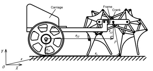
The new quadruped walking machine proposed in this study consists of two parts: the quadruped walking mechanism and the carriage, as shown in Fig. 1. The walking mechanism generates leg movement, while the main function of the carriage is to maintain the balance of the walking mechanism. This walking mechanism consists of four identical leg mechanisms. The front and rear legs on the right and left sides are oriented in opposite directions. The leg mechanism is an eight links (links 1, 2, 3, 4, 5, 6, 7, and 8) linkage with ten joints (joints a, b, c, d, e, f, g, h, i, and j, where joints b, d and e are multiple joint). Each leg mechanism is composed of two crank-rocker mechanisms (links 1, 2, 3, 4 and links 1, 2, 5, 6). The output links of the two crank-rocker mechanisms drive the leg in a four-bar linkage (links 4, 6, 7, 8) in order to produce the functions of knee bending and leg lifting. The way of assembling the four legs is as follows: Connect the right front leg and right rear leg, left front leg and left rear leg at the crank (link 2) to form the leg mechanisms of the right and left sides respectively. Then rotate the crank of the leg mechanism of left side by 180° and connect it with the leg mechanism of right side at the crank shaft to form the walking mechanism. Finally, connect the walking mechanism with the carriage to complete the quadruped walking machine.
Fig. 1Quadruped walking machine
a) Vector loop diagram
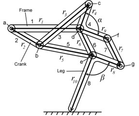
b) Leg mechanism
In the quadruped walking machine in this study, the walking mechanism is formed from four identical 8-link leg mechanisms. The four legs share the crank and the frame of walking machine; therefore, the walking mechanism has 26 links. The frame of walking machine and the carriage are fixed together and considered as one link. Including the wheel and the ground, the mechanism of the quadruped walking machine has total of 28 links. The walking mechanism has 37 revolute pairs (the crank is a 5-joint link). There is also one revolute pair between the wheel and the carriage, and one rolling pair between the wheel and the ground. The point of contact between the support leg and the ground is seen as one revolute pair. Therefore, the quadruped walking machine has a total of 39 revolute pairs and 1 rolling pair. According to the planar degrees of freedom formula [20], the degrees of freedom, , of the quadruped walking machine is as follows:
3. Equation of motion
If all the members of a single-degree-of-freedom mechanical system are rigid bodies and neglecting friction, their motions can be represented by a second-order non-linear differential equation [17] as:
which is also known as the generalised equation of motion. And, is the angular displacement of the input link, is the generalised inertia, , and is the generalised moment.
If a mechanism is formed by links, then and in Eq. (2) can be represented as:
where is the mass of link , is the mass moment of inertia of link , is the kinematic coefficient of link relative to the input link and and are the kinematic coefficients of the centre of gravity of link in the and axes respectively relative to the input link. The details with regard to deriving the kinematic coefficients of each link and its center of gravity, generalised moment and the position analysis can be referred to the reference [19].
When the driving torque is applied on the crank shaft, the generalised moment for the quadruped walking machine is hence:
When the driving torque is applied on the wheel shaft, the generalised moment is then:
where is the driving torque on the crank shaft, is the driving torque on the wheel shaft, is the reaction torque on the frame of walking machine, and is the torque generated by the gravity force of each link in the quadruped walking machine. The flow chart using the equation of motion for dynamic analysis of the quadruped walking machine is shown in Fig. 2.
4. Results and discussion
The dimensions of the new quadruped walking machine are listed in Table 1. For optimizing the construction of the quadruped walking machine, three crank arrangements are proposed as shown in Table 2. The symbols RF, LF, RR and LR in Table 2 indicate the right front, left front, right rear and left rear leg, respectively. Type A is the design in which there is no phase angle between the cranks of front and rear legs on the same side and there is 180° between the legs on the different side. Type B is the design that there is 90° between the front and rear legs on the same side and there is 180° between the legs on the different side. Type C is another design that there is 180° between the front and rear legs on the same side and there is 90° between the legs on the different side. Fig. 3 illustrates the velocities with different construction of crank arrangements. The fluctuation of the design A is smaller and the motion is smoother. But the fluctuation of design C is great. The velocity difference of the design A between the current and next support legs is smaller, thus reducing deceleration and skidding and making the speed more stable. Therefore, this optimized construction of crank arrangements is selected in order to obtain stable motion while walking.
The existing wooden horse carriage is a miniature and is driven by way of wheel shaft. To realistically simulate the walking manners of a horse, the driving torque should act on the crank shaft. Fig. 4 illustrates the dynamic response of the new quadruped walking machine under a driving torque on the shaft of the wheel and the shaft of the crank. When the driving torque acts on the wheel shaft and crank shaft after 1.5 sec, the carriage speed fluctuates at 0.36 m/sec and 0.70 m/sec respectively. The results show that when the driving torque acts on the crank shaft, the carriage velocity is faster. However, when the driving torque acts on the wheel shaft, the carriage velocity is slower. Therefore, in the analysis that follows, the driving torque of the quadruped walking machine acts only on the crank shaft in order to obtain better transmission efficiency.
Fig. 2Flow chart
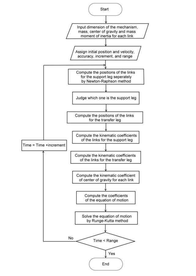
Table 1Dimensions of the quadruped walking machine
Parameter | mm | Parameter | mm | Parameter | deg |
27.5 | 25.0 | 85.0 | |||
9.0 | 25.0 | 90.0 | |||
40.0 | 25.0 | 34.0 | |||
25.0 | 25.0 | 120.0 | |||
40.0 | 45.0 | 34.0 |
Table 2Construction of Crank arrangements
Type | A | B | C |
Phase angle | 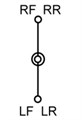 | 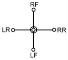 | 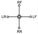 |
Fig. 3Velocities with different constructions
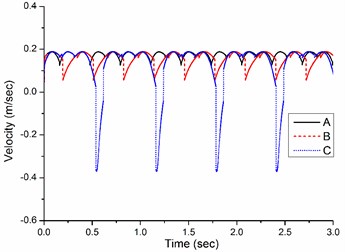
Fig. 4Dynamic response of the walking machine
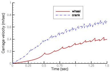
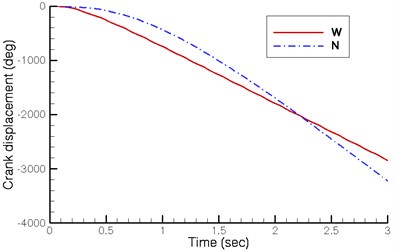
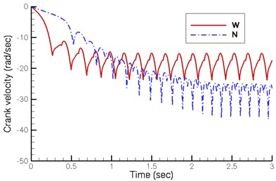
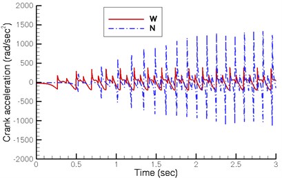
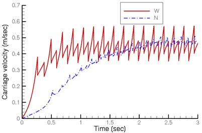
Fig. 5 shows the displacement, velocity and acceleration of the crank shaft under a driving torque of 0.004 Nm on the new design (N) proposed by this study and a driving torque of 0.014 Nm on the existing wooden horse carriage (W) restored by Yan’s research group. Fig. 5(b) indicates that the stable angular velocity of the crank shaft in both designs fluctuates at 20.0 rad/sec and 30.0 rad/sec respectively. Though the existing quadruped walking machine demonstrates greater initial acceleration and reaches stable velocity in a shorter time, its final velocity is lower.
Fig. 5Dynamics of crank shaft
a)
b)
c)
The simulated analysis in this study does not consider the damping effects. Theoretically, the quadruped walking machine should continuously accelerate while the driving torque is applied. However, the results of the simulation are different. The reason is that the four legs of the quadruped walking machine are braced against the ground in turn and, at the instant of changing the support leg, the velocities of the two legs differ. When the walking machine animates forward, the velocity of the next support leg is less than that of the current support leg. Therefore, changing support leg slows the entire walking machine and cause skidding as well. The velocity of the walking machine is thereby suddenly reduced by a loss of energy. When the input energy and energy loss reach the balance, the walking machine moves at a stable speed. Besides, the velocity difference of the proposed new design between the two legs is smaller, thus reducing deceleration and skidding.
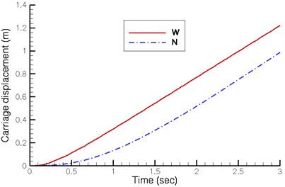
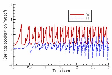
Fig. 6 illustrates the displacement, velocity and acceleration of the carriage. Though the angular crank velocity of the existing walking machine is lower, its stroke is greater, equalizing the final carriage velocity of both designs. But the new quadruped walking machine requires lower driving torque. Besides, the existing walking machine demonstrates a greater fluctuation in velocity while changing support leg. The velocity of the proposed new walking machine in this study is significantly more stable in comparison.
Fig. 6Dynamics of carriage
a)
b)
c)
The walking machine down the slope can move automatically when the torque generated by the gravity force of all links in any crank position of the quadruped walking machine is greater than zero. Fig. 7 shows the velocity of automatic walking when the walking machine is traveling downward. The changes in the vertical height of the crank shaft are greater in the current design, resulting in a higher critical angle of about 4°. In the new design, the critical angle is only about 3°. Fig. 7 shows the average velocity of the carriage is approximately 0.35 m/sec in the current design and approximately 0.60 m/sec in the new design. Therefore, the new design demonstrates greater and more stable velocity.
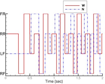
Fig. 8 shows the sequence of the support legs. The support leg sequence of proposed design is as follows: left front leg, left rear leg, right front leg and right rear leg. The support leg sequence of existing design is: right rear leg, right front leg, left rear leg and left front leg. The support leg sequences of two designs are in reverse.
Fig. 7Dynamic response during downhill
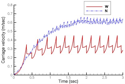
Fig. 8Support leg sequence
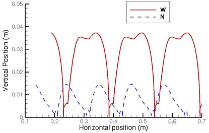
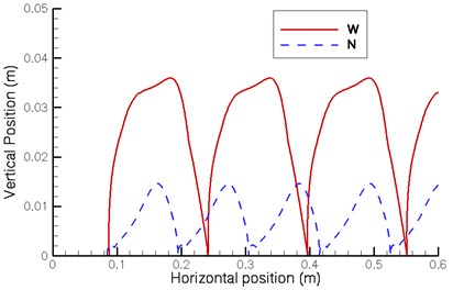
The foot trajectory curves typically use the frame of walking machine as the reference coordinate. When one leg returns to its original position after a cycle, the curve of the foot trajectory should be a closed curve. However, because the walking machine itself is in motion, the foot trajectory cannot be a closed curve compared to the fixed coordinate. Therefore, this study used the ground as the reference coordinate to investigate the foot trajectory of the walking machine. Fig. 9 illustrates the foot trajectory curves of the front and rear legs. For highlighting the displacement in the vertical direction, the horizontal and vertical scales are different.
Fig. 9 shows that the stroke of the proposed design (N) is approximately 0.11 m and its stride height is approximately 0.015 m. The stroke of the existing walking machine (W) is approximately 0.15 m and its stride height is approximately 0.036 m. In the foot trajectory of the proposed design, the front leg is lifted slightly and lowered again before touching the ground, and the rear leg is lowered slightly and lifted again after leaving the ground. In the foot trajectory of the existing walking machine, the front leg pauses slightly after leaving the ground and at the highest point is slightly lowered before lifting to the highest point. This phenomenon is less evident in the rear leg possibly due to the changes in pitch angle. The ideal foot trajectory curve resembles a smooth curve; therefore, there is still a room for the improvement of the foot trajectory for both designs.
Fig. 9Foot trajectory
a) Front leg
b) Rear leg
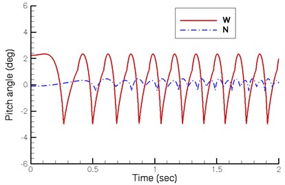
Fig. 10 illustrates the changes in the pitch angle of the walking machine. The pitch angle of the existing design is considerable, ranging between –3.0° and +2.4°. However, the proposed design is much smaller, ranging between –0.5° and +0.5°. The reason is that the variations in the height of the crank shaft produce changes in the pitch angle. The height of the crank shaft of existing design ranges from 0.062 m to 0.073 m, indicating a considerable variation. This causes the oscillating and pitching of the horse carriage.
Fig. 10Pitch angle
5. Conclusion
The purpose of this study is to propose and investigate the dynamics of a quadruped walking machine. The optimized construction of the crank arrangements shows that the phase angle between front and rear legs on the same side should be 0° and the one between the legs on the different sides should be 180°. The simulated results also demonstrate better transmission efficiency when the driving torque of the quadruped walking machine acts on the crank shaft. When the quadruped walking machine moves automatically during downhill, the critical angle of the proposed new design is only 3° but the existing design is 4°. The pitch angle of the existing design is considerable, ranging between –3.0° and +2.4°. However, the new quadruped walking machine has fewer changes in pitch angle, ranging between –0.5° and +0.5°. Therefore, the pitching is reduced and its movement is more stable. When changing support leg, the velocity difference of the proposed new design between the two legs is smaller, thus reducing deceleration and skidding. However, its stroke is smaller and its stride height is lower. There is also a room for improvement in the foot trajectory of both walking machines. The results of this study can serve as a reference for future optimization of the ancient Chinese wooden horse carriage and other walking machines.
References
-
Rygg L. A. Mechanical horse. U. S. Patent 491, 1893, p. 927.
-
Shigley J. E. The mechanics of walking vehicles. Land Locomotion Laboratory Report No. LL.71, U. S. Army Tank-Automotive Command, Warren, Michigan, 1960.
-
Mosher R. S. Test and evaluation of a versatile walking truck. Proceedings of Off-Road Mobility Research Symposium, International Society for Terrain Vehicle Systems, Washington, 1968, p. 359-379.
-
McGhee R. B.,Frank A. A. On the stability properties of quadruped creeping gaits. Mathematical Biosciences, Vol. 3, 1968, p. 331-351.
-
Hirose S.,Umetani Y. The basic motion regulation system for a quadruped walking machine. ASME Paper 80-DET-34, 1980.
-
Raibert M. H., Chepponis M., Brown H. B. Running on four legs as though they were one. IEEE Journal of Robotics and Automation, Vol. 2, Issue 2, 1986, p. 70-82.
-
Lee T. T.,Shih C. L. A study of the gait control of a quadruped walking vehicle. IEEE Journal of Robotics and Automation, Vol. 2, Issue 2, 1986, p. 61-69.
-
Buehler M., Battaglia R., Cocosco A., Hawker G., Sarkis J., Yamazaki K. SCOUT: A simple quadruped that walks, climbs, and runs. Proceedings of the 1998 IEEE International Conference on Robotics and Automation, Vol. 2, 1998, p. 1707-1712.
-
Chen Y. G. On the design of a quadruped walking machine with a single actuator. Ph. D. Dissertation, National Cheng Kung University, Tainan, Taiwan, 2003.
-
Yan H. S. Reconstruction designs of lost ancient Chinese machinery. Springer, Netherlands, 2007.
-
Yan H. S. A systematic approach for the restoration of the wooden horse carriage of ancient China. Proceedings of the International Workshop on History of Machines and Mechanisms Science, Moscow, Russian, 2005, p. 199-204.
-
Yan H. S. Ancient mechanical horse carriages: from basic research to science education in museums. Proceedings of IFToMM, World Congress Paper A21-271, 2011.
-
Greenwood D. T. Principles of dynamics. Prentice-Hall, Inc., Englewood Cliffs, New Jersey, 1988.
-
Myklebust A., Fernandez E. F., Choy T. S. Dynamics of slider-crank machines during startup. ASME Journal of Mechanisms, Transmissions, and Automation in Design, Vol. 106, 1984, p. 452-457.
-
Cveticanin L., Maretic R. Dynamic analysis of a cutting mechanism. Mechanism & Machine Theory, Vol. 35, 2000, p. 1391-1411.
-
Chen F. C.,Tzeng Y. F. On the dynamics of spring-type operating mechanism for gas insulated circuit breaker in open operation using Lagrange equation. Journal of Mechanical Engineering Science, Vol. 216, Issue 8, 2002, p. 831-843.
-
Paul B. Kinematics and dynamics of planar machinery. Prentice-Hall, Inc., Englewood Cliffs, New Jersey, 1979.
-
Zadoks R. I.,Modha A. A method for calculating the steady-state yynamic response of rigid-body machine system. ASME Journal of Mechanisms, Transmissions, and Automation in Design, Vol. 109, 1987, p. 435-442.
-
ChenF. C.,Tzeng Y. F.,Chen W. R.,Yan H. S. On the motion of a reconstructed ancient Chinese wooden horse carriage. Mechanism and Machine Theory, Vol. 58, Issue 12, 2012, p. 165-178.
-
Waldron K. J.,Kinzel G. L. Kinematics, dynamics, and design of machinery. John Wiley & Sons, Inc., New York, 1999.
About this article

The authors are grateful to the National Science Council of Taiwan, the Republic of China for supporting this research under grant NSC 102-2221-E-168-006.
