Abstract
An experimental test was performed to evaluate the seismic resistance of reinforced concrete beam-column joints rehabilitated with FRP sheets and Buckling Restrained Braces (BRBs). Six beam-column joints were rehabilitated and tested. The test results were compared in terms of hysteresis loops, stiffness degradation, energy dissipation and ductility. The comparison result showed that wrapping FRP sheets can contribute to increase the effect of confinement and to delay crack development in the joints. Also retrofitting buckling restrained braces (BRBs) can improve the stiffness and energy dissipation capacity. Both FRP sheets and BRBs can effectively improve the strength, stiffness and ductility.
1. Introduction
Beam-column joints must remain essentially elastic to ensure the stability of the structure under earthquakes. Inadequate details of beam-column joints cause high shear stress, which may result in brittle failure of the joints and total collapse of structures. In order to deal with this problem, rehabilitation of beam-column joints is very important. It is necessary to repair and rehabilitated reinforced concrete structures that have already sustained damage or are likely to in the future. Rehabilitation by wrapping concrete member with fiber reinforced polymer (FRP) sheets increases ductility due to high tensile strength of FRP so it has an effect on delaying shear failure [1, 2]. Pampanin et al. suggested the analysis method to predict structural performance in beam-column joint rehabiltated with CFRP [3]. Gergely et al. verified improved performance in joint such as maximu load, energy dissipation, ductile behavior through the experiment of beam-column joint rehabilitated with CFRP composite [4]. Therefore, this method is widely used to improve seismic resistance capacity of structures [5-7]. Buckling Restrained Braces (BRB) are designed to withstand inelastic deformation. They provide substantial energy dissipation and ductility through the stable hysteresis behavior. Consequently, BRB system is an effective way to prevent damage to beam-column joints and columns for both new and retrofit constructions under large seismic loads [8-10]. It is possibly expected to secure the sufficient lateral resistance capacity when both FRP sheet wrapping method and BRB system are applied simultaneously. In this research, improvement of seismic performance is evaluated experimentally by applying FRP sheet and BRB to rehabilitation of reinforced concrete beam-column joints. Some specimens were rehabilitated by combination of FRP wrapping method and BRB. Based on the results in terms of maximum load, ductile behavior, and energy dissipation, it was performed to evaluate of seismic performance of the beam-colum joints in rehabilitation methods.
2. Experimental program
2.1. Test specimens and materials
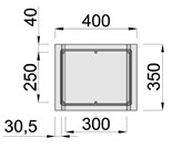
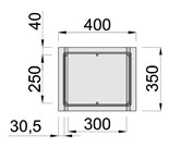
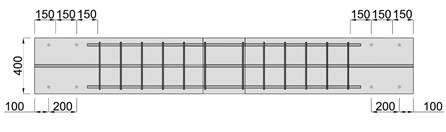
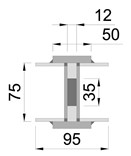
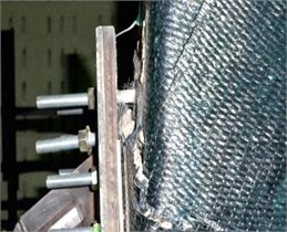
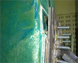
Six one-half scaled beam-column specimens were manufactured in order to evaluate seismic performance. All specimens have the same cross-sectional dimensions. Geometry and reinforcement details are given Fig. 1; height of column is 1500 mm and length of beam is 2700 mm with cross sections of (300×400) mm and (400×350) mm respectively. 28 day compressive strength of concrete was measured to be 24 MPa. The yield strength of longitudinal bars with 19 mm diameter and stirrups with 10 mm diameter was 400 MPa. In this study, the BRB system proposed by Shin et al. [11] was used for the test. The yield strength of steel for BRB system was 235 MPa and two U-shape channels were attached to the both sides of a central core to prevent buckling of the core. Each U-shaped channel was welded using eight steel plates. To maximize the stiffness of the core, the core was designed to resist only against the axial force. For this purpose, rubber sheets were attached between the core and the U-shaped cannels, so that the steel core and the channels would behave independently under the load. Dimensions and details of BRB system are given in Fig. 2. Aramid FRP (AFRP) and carbon FRP (CFRP) sheets were used, respectively. The FRP sheets were wrapped in two layers on 60° with respect to the longitudinal axis of the column. Material properties of AFRP and CFRP sheets are presented in Table 1. Notations used for various test specimens are listed in Table 2.
Fig. 1Geometric properties and reinforcement details
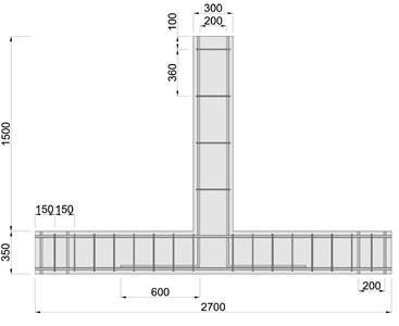
a) Beam-column front view
b) Beam section
c) Column Section
d) Beam reinforcement placing details
Fig. 2Dimensions of the BRB
a) Section
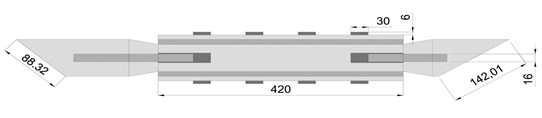
c) Front view
b) Welding Plate
d) Top view
Table 1Material properties of FRP sheets
Modulus of elasticity (MPa) | Tensile strength (MPa) | Thickness (mm) | |
CFRP | 2.35×10⁵ | 3.550 | 0.18 |
AFRP | 1.20×10⁵ | 2.880 | 0.18 |
Table 2Description of specimens
Number | Specimen notation | Rehabilitation method |
1 | Control | Control specimen |
2 | BRB | BRB |
3 | CFRP | CFRP sheet |
4 | AFRP | AFRP sheet |
5 | CFRP-BRB | CFRP sheet + BRB |
6 | AFRP-BRB | AFRP sheet + BRB |
2.2. Test setup
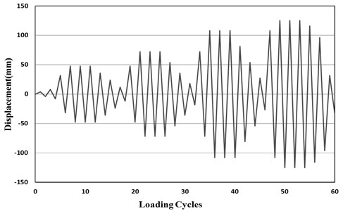
The experimental set-up is schematically illustrated in Fig. 3. The bottom of the column was connected to the base by a hinge support and the beam was connected to the base at its ends by fixed supports. Sustained axial load was applied to the column using a 300 kN capacity hydraulic jack. The magnitude of the axial load was 10 % of axial capacity of the column and kept constant during the test. Cyclic lateral loading was applied to the top of the column using a 1,000 kN capacity hydraulic actuator by displacement control. The loading protocol consisted of three cycles as shown in Fig. 4.
Fig. 3Test set-up
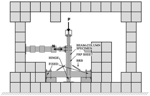
Fig. 4Loading protocol
3. Experimental results
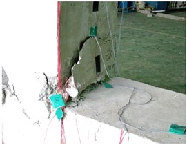
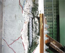
3.1. Failure modes of specimens
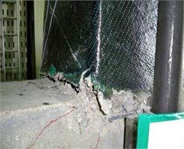
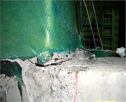
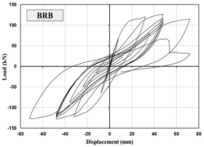
Fig. 5 shows the failure modes. For the control specimen, the flexural cracks occurred on the beam during the initial loading stages. Cracks then developed outside and shear cracks observed in the beam-column joints region, then shear cracks developed wider as the load increased. No cracks were observed in the column faces. Concrete was crushed near the joints and longitudinal bars of column were yielded after the maximum load. The failure patterns for BRB specimen was similar as control specimen at initial loading stages. However, shear cracks with -shape in the beam-column joints progressed along the direction of the column unlike control specimen. This is because energy dissipation had taken place in the beam-column joint by the BRB. After the maximum load, concrete spalling appeared in the column.
Fig. 5Failure modes of the specimens
a) Control
b) BRB
c) CFRP
d) AFRP
e) CFRP + BRB
f) AFRP + BRB
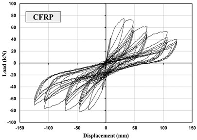
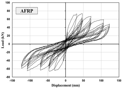
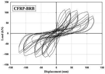
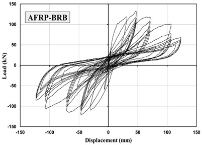
For CFRP and AFRP specimens, flexural cracks occurred in the beam at initial loading stage. Then, shear cracks developed in beam-column joints. As the load increased, concrete spalling occurred in the beam-column joints. For CFRP-BRB and AFRP-BRB specimens, shear cracks were observed in the joint then the cracks occurred adjacent to BRB. And rupture of FRP sheets was taken place. Both CFRP-BRB and AFRP-BRB specimens were failed by the pull-out of the anchors in the BRB. Also minor shear cracks in the joint were found.
3.2. Strength and stiffness
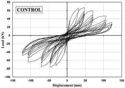
The load-displacement hysteresis curves of specimens are presented in Figs. 6 and 7. Also, the test results are summarized in Table 3. The maximum load capacity of the CFRP and AFRP specimens were increased by approximately 10 % and 9 % compared with the control specimen. Regardless of elasticity modulus and tensile strength of FRPs, the test results of CFRP and AFRP specimens showed similar load capacity in terms of maximum load. The maximum load capacities of BRB, CFRP-BRB, AFRP-BRB specimens were significantly higher than the control specimen. This is due to the increased strength of joints resulting from BRB system. However, for BRB specimen, the load capacity dropped dramatically after the maximum load. CFRP-BRB and AFRP-BRB specimens showed more ductile behaviors than that of BRB specimen. Test result indicated that the wrapping of FRP sheets effectively contributed to ductile behavior of beam-column joint.
Table 3Maximum load
Specimen | Maximum load (kN) | Ratio of maximum load |
Control | 67.20 | 1.00 |
BRB | 126.96 | 1.89 |
AFRP | 73.15 | 1.09 |
CFRP | 74.17 | 1.10 |
CFRP-BRB | 131.56 | 1.96 |
AFRP-BRB | 133.15 | 1.98 |
Fig. 6Relationship of lateral load versus displacement
a) Control
b) BRB
c) CFRP
d) AFRP
e) CFRP+BRB
f) AFRP+BRB
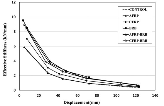
To evaluate seismic performance of different rehabilitation methods, effective stiffness of the specimens are plotted in Fig. 8 and summarized in Table 4. The effective stiffness is defined as the slope of the line joining the highest load points in the load versus displacement curve attained at each displacement level [12]. It can be obviously seen that the initial stiffness of all specimens were almost the same except the control and AFRP specimens. The effective stiffness of BRB, AFRP-BRB and CFRP-BRB specimens increased by approximately 70 % compared with the control specimen. This result indicates that BRBs contributes to the effective stiffness of beam-column joints. The control and AFRP specimens showed similar effective stiffness while CFRP specimen exhibited an increase in effective stiffness.
Fig. 7Hysteresis curves for the specimens

Table 4Effective stiffness
Specimen | Displacement (mm) | |||
48 | 72 | 108 | 125 | |
Control | 1.54 | 0.94 | 0.52 | 0.32 |
BRB | 2.62 | 1.76 | – | – |
CFRP | 2.23 | 1.29 | 0.75 | 0.51 |
AFRP | 1.56 | 0.92 | 0.58 | 0.43 |
CFRP-BRB | 2.55 | 1.62 | 1.00 | 0.72 |
AFRP-BRB | 2.73 | 1.76 | 0.98 | 0.62 |
Fig. 8Effective stiffness of the specimens
3.3. Energy dissipation and displacement ductility
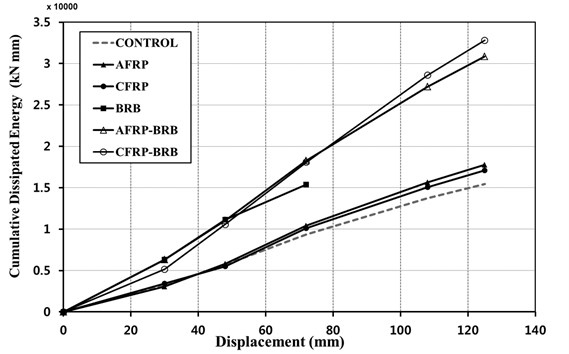
Energy dissipation of specimens under cyclic loading has been calculated by summing enclosed area within the load versus displacement hysteresis curves at different loading cycles. The cumulative energy dissipation is plotted in Fig. 9 and summarized in Table 5. AFRP and CFRP specimens were increased by approximately 11 % and 15 % when compared to the control specimen, respectively. The energy dissipation capacity was significantly improved in the case of retrofitted using BRB system compared to the control, CFRP and AFRP specimens. For BRB, CFRP-BRB and AFRP-BRB specimen had almost same energy dissipation capacity at the initial loading stage. However, since BRB specimen was failed at the second loading cycle, it represents the lowest energy dissipation capacity. Specimens retrofitted FRP sheets and BRBs indicated the highest energy dissipation capacity.
Table 5Cumulative energy dissipation
Specimen | Cumulative dissipated energy (kN mm) | |||||
Maximum displacement at each loading stage (mm) | Ratio | |||||
30 | 48 | 72 | 108 | 125 | ||
Control | 3211 | 5698 | 9376 | 13740 | 15449 | 1.00 |
BRB | 6335 | 11141 | 15395 | – | – | 1.00 |
CFRP | 3410 | 5496 | 10091 | 15056 | 17080 | 1.11 |
AFRP | 3086 | 5802 | 10405 | 15646 | 17781 | 1.15 |
CFRP-BRB | 5161 | 10570 | 18066 | 28584 | 32802 | 2.12 |
AFRP-BRB | 6310 | 11044 | 18259 | 27185 | 30835 | 2.00 |
Fig. 9Cumulative energy dissipation of the specimens
In this paper, the displacement ductility was computed by the following equation:
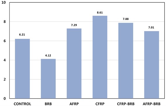
where is the ductility index, the ultimate displacement, , is defined as the displacement corresponding to a 80 % strength degradation of the maximum strength, , is defined as the displacement corresponding to the first yielding of the specimen. Fig. 10 and Table 7 present the displacement ductility index of the specimens. As shown in Fig. 10, all specimens exhibit higher displacement ductility index than the control specimen except BRB specimen. BRB specimen exhibited brittle failure at the anchorage of BRB to concrete, and the displacement remained relatively low at 27 mm. Hence, BRB specimen has less ductility than that of the specimens retrofitted with FRP sheets and BRB. The specimens retrofitted with FRP sheets increased approximately 24 % in average.
Table 7Displacement ductility index
Specimen | (mm) | (mm) | Ratio | |
Control | 13.88 | 86.02 | 6.21 | 1.00 |
BRB | 12.89 | 53.10 | 4.12 | 0.66 |
CFRP | 10.86 | 79.12 | 7.29 | 1.17 |
AFRP | 12.60 | 108.50 | 8.61 | 1.39 |
CFRP-BRB | 14.38 | 113.32 | 7.88 | 1.27 |
AFRP-BRB | 14.62 | 102.42 | 7.01 | 1.13 |
Fig. 10Displacement ductility index
4. Conclusions
In this paper, cyclic loading test was performed on six beam-column joint specimens using the various rehabilitation methods. Their failure modes, maximum loads, effective stiffness, energy dissipation and displacement ductility were investigated. Effectiveness of FRP sheets and BRBs in improving the seismic performance of beam-column joints was evaluated through the test. From the test results, control specimen was likely to be damaged at an early loading stage and may result in unstable seismic performance. The retrofit mehtod with FRP sheets contributed to the increase of confinement effect and delay of cracking. Also, BRB system can improve the stiffness and energy dissipation capacity when used with FRP wrapping method. The test results demonstrated that retrofit method with both FRP sheets and BRB system can effectively improve the shear strength, effective stiffness and energy dissipation of seismically deficient beam-column joints.
References
-
ACI Committee 440: Guide for the Design and Construction of Externally Bonded FRP System for Strengthening Concrete Structures. American Concrete Institute, USA, 2002.
-
Wang Y., Restrepo J. I. Investigation of concentrically loaded reinforced concrete columns confined with glass fiber-reinforced polymer jackets. ACI Structural Journal, Vol. 98, Issue 3, 2001, p. 377-385.
-
Pampanin S., Bolognini D., Pavese A. Performance-based seismic retrofit strategy for existing reinforced concrete frame systems using fiber reinforced polymer composites. Journal of Composite for Construction, Vol. 11, Issue 2, 2007, p. 211-226.
-
Gergely J., Pantelides C. P., Reaveley L. D. Shear strengthening of RCT-joints using CFRP Composites. Journal of Composite for Construction, Vol. 4, Issue 2, 2000, p. 56-64.
-
Akguzel U., Pampanin S. Effect of variation of axial load and bidirectional loading on seimic performance of GFRP retrofitted reinforced concrete exterior beam-column joins. Journal of Composite for Construction, Vol. 14, Issue 1, 2010, p. 94-104.
-
Almusallam T. H., Al-Salloum Y. A. Seismic response of interior beam-column joints upgraded with FRP sheet. Journal of Composite for Construction, Vol. 11, Issue 6, 2007, p. 575-589.
-
Liu C., Chiang M., Chuang W. Lean transformation for composite-material bonding process. International Journal of Engineering and Technology Innovation, Vol. 2, Issue 1, 2012, p. 48-62.
-
Black C. J., Makris N., Aiken I. D. Component testing, seismic evaluation and characterization of buckling-restrained braces. Journal of Structural Engineering, Vol. 130, Issue 6, 2004, p. 880-894.
-
Lopez W. A., Gwie D. S., Lauck T. W., Saunders C. W. Structural design and experimental verification of a buckling-restrained braced frame system. Engineering Journal, Vol. 41, 2004, p. 177-186.
-
Berman J. W., Bruneau M. Cyclic testing of a buckling restrained braced frame with unconstrained gusset connections. Journal of Structural Engineering, Vol. 135, Issue 12, 2009, p. 1499-1510.
-
Shin J., Lee K., Jeong S. H., Lee H. S., Kim J. Experimental and analytical studies on buckling-restrained knee bracing systems with channel sections. International Journal of Steel Structure, Vol. 12, Issue 1, 2012, p. 93-106.
-
Tsonos A. G. Lateral load response of strengthened RC beam-to-column joint. ACI Structural Journal, Vol. 96, Issue 1, 1999, p. 46-56.
About this article

This work was supported by the National Research Foundation of Korea (NRF) Grant funded by the Korea Government (MSIP) (No. NRF-2011-0016332).
