Abstract
For the fault rotor – bearing system caused by transverse open crack. The dynamic model of crack rotor system is established by the crack compliance coefficient matrix which is derived from the stress intensity factor and strain energy density function. The stiffness matrix of rotor system which contains transverse crack faults is different from the health rotor. So the surplus dynamics equation of cracked rotor system can be deduced by comparing the dynamics equations of the crack fault and health rotor system, which is on the basis of getting the compliance coefficient matrix. Furthermore, the information of open crack’s location and crack’s depth can be extracted from the vibration signal by analyzing force condition on both ends of the shaft segment where crack exist and combining with the residual dynamic equation. The extraction method for crack information only needs to collect the vibration signals of the three different node positions under two different speeds. Finally, the feasibility of the method can be verified with simulation and experiment.
1. Introduction
It is pretty common for large-unit rotor system such as air separation equipment to suffer from fatigue crack problem. Longtime running, over heat and additional moment caused by machining error could all lead to transverse crack of a running rotor system. Further expansion of the crack will cause paroxysmal damage of the rotor system and furthermore, unstable movement and shaft damage of the system. Analyzing the vibration character of the cracked rotor system and extracting the crack information from vibration signal can effectively estimate the position and depth of a crack. Study on the method of extracting crack information has become an important direction of the study on cracked rotor problem.
For years, scholars both home and abroad have made loads of related studies on the complicated dynamic phenomenon of cracked rotor system and made some important achievement. Dimarogonas, Papadopoulos [1], by studying the cracked rotor system, brought forward that the impact of the crack upon the vibration characteristics of rotor lies on the variation of rotor stiffness matrix, and used the crack flexibility function to express that variation. Gounaris, Dimarogonas [2], based on the methods of fracture mechanics, brought forward the crack unit of Euler-Bernoulli beam model. Jibing Zheng and Guang Meng [3] analyzed the dynamic behaviors of the cracked rotor under the impact of nonlinear whirl, especially the bifurcation of system response and chaos characteristics, and found many occasions where period 3 solution becomes other periodic solution as the initial value varies. Darpe, Gupta, etc [4], using the nonlinear respiratory crack model, studied the responses under the influence of the coupling effect of vertical vibration, transverse vibration and torsional vibration of the cracked shaft. This paper established the dynamic model of cracked rotor system by using the crack flexibility matrix and obtained the residual dynamic equation of the cracked rotor system by comparing the dynamic equations of healthy and cracked rotor system. Based on that equation, it deduced the method for determining the position and depth of the open crack, and verified its feasibility through simulation and experiment.
2. Dynamic model of fault rotor system
2.1. Crack model
Suppose that a shaft segment unit, given a certain stiffness, has a transverse crack whose depth is , and force - applied on either side of it. As shown by Fig. 1(a), and are axial forces; , , , are shear forces; , , , are bending moments circling and axis, and and are torques. The section’s semidiameter is , the crack’s width is , and the meanings of , and are shown as in Fig. 1(b).
Fig. 1Parameters of crack model
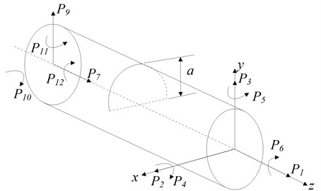
a)
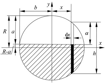
b)
Based on Paris’ equation [5], we can get the additional displacement caused by the crack in direction:
where – strain energy density function, find in reference [6-9] for detail. – relative load in direction.
The crack flexibility coefficient is (2 in width):
The flexibility coefficients can constitute the crack flexibility matrix, whose order rests with the degree of freedom of the nodes on the shaft segment. When bending vibration is considered solely, the crack flexibility matrix is:
The relative flexibility coefficients in matrix are:
where is material shearing coefficient, is the elastic modulus of the shaft segment material. The details of the other coefficients as follows:
The influence upon the rotor system by the crack can be denoted by the variation of the stiffness of the cracked shaft segment. Suppose that the flexibility matrix of a non-cracked rotor shaft segment is:
where is the section inertia moment of the shaft segment, is the elastic modulus of the shaft material and is the length of the shaft segment.
So the whole flexibility matrix of the rotor shaft segment with crack can be expressed as:
Accordingly, the stiffness matrix of the cracked rotor shaft segment is:
where, is the stiffness transition matrix of the cracked shaft, details of which can be found as follows:
2.2. Dynamic model of the cracked rotor system
The rotor system can be divided into several shaft segments with two nodes at each segment. When only considering bending vibration, there are 4 degrees of freedom and the coordinate of the rotor system in a broad sense can be defined as:
The non-cracked rotor system’s quality, stiffness, damping matrix, gyroscopic matrix and activation vector are , , , , respectively, thus the differential equation of motion of the non-cracked rotor system is:
If the rotor system is divided into segments and there is crack at the -th segment, at this time the quality, damping and gyroscopic moment will not vary, only the stiffness matrix transforming into:
where is the form into which expanded. Thus the differential equation of motion of cracked rotor system is:
Subtract Eq. (7) from Eq. (8) gives the residual dynamic equation of the cracked rotor system:
where is the residual vibration quantity [10].
3. Determining the coefficients of the crack position
As the crack only exists at the -th segment, in detail is as follows:
where is a ×-dimensioned 0-matrix.
As only contains non-zero factors in Eq. (10), the left end of Eq. (9) can transform into:
where is the crack-caused additional force at either end of the cracked shaft segment.
As the flexibility factors of the open crack do not alter in rotation, from Eq. (11) we know that  is in simple harmonic variation. The Eq. (9) can be expressed in complex number:
Suppose , from Eq. (12) we get:
Based on the stress condition of the two ends of the shaft segment, can be expressed by the force at one side of the cracked shaft and moment component [11-15], so Eq. (13) can be changed into:
where is shown as follows:
In light of the actual form of in Eq. (11), only the column from 43 to 44 have practical sense. If the residual vibration quantity of nodes and of the shaft segment in and direction and node in either direction ( or ) are known, from Eq. (14) we have:
Based on Eqs. (14) and (16), we can derive the expression of the residual vibration quantity of node in and direction ( direction as an example):
where:
Thus the position of the crack can be estimated by the following expression:
where is the response of node k obtained from simulation or experiment.
Based on Eq. (19), go through 1, 2,…, and get the value of of each shaft segment, and the one with the smallest value of is where the crack happens.
4. Extraction of the depth of the crack
According to Eq. (3), the information about the depth of the crack is contained in the flexibility coefficient, thus it is essential to obtain the crack flexibility coefficient of the rotor system to solve the crack depth problem [16-18].
From Eq. (11) we get:
where is the response vector at the two ends of the segment where the crack happens, and can be obtained from Eq. (16).
From Eq. (20) we have:
Clean up and we get:
where, so from Eq. (22) we have:
Assume , , so from Eq. (23) we get:
After the position R of the cracked segment is determined, the is known, thus , , , , , , , can all be derived. The four Eq. (24) have five unknown crack flexibility coefficients. In order that the crack flexibility coefficients can be solved, we take two different rotation frequency , solve its corresponding by Eq. (8). From Eq. (3) we know that the crack flexibility coefficients do not vary according to rotation frequency , thus, given two different frequencies, we have eight equations to solve five unknown numbers. This is an incompatible equations and we can derive the crack flexibility coefficients , , , and by the method of least squares.
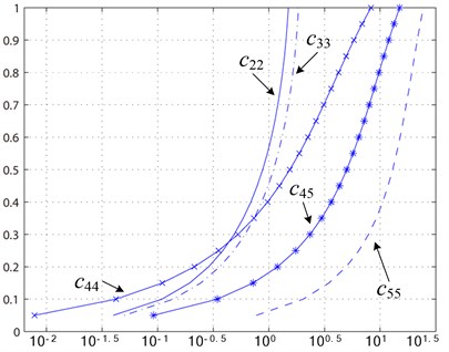
Fig. 2 shows that the crack flexibility coefficient vary as the dimensionless crack depth. We can see from the figure that each crack flexibility coefficient corresponds with dimensionless crack depth . Substitute the obtained , , , and into Eq. (3), we have the corresponding dimensionless crack depth , , , and . Then we can calculate the mean of them and get dimensionless crack depth , which is further used to derive the crack depth .
Fig. 2Crack flexibility coefficient
5. Numeric simulation
Take the single span rotor with a single disk as an example, the cracked rotor system going through finite-element model of discretization is shown by Fig. 3, in which the dots are nodes and the number denotes the segment number. The disk’s diameter is of 60 mm at segment 3; the two bearings at each sides are at segment 1 and 13 and the two supporting bearings are simplified as spring damper.
Coefficient of each shaft segment unit of the rotor system is shown in Table 1.
The elastic modulus of the rotor system is 2.1×10¹¹ Pa, density being 7850 kg/m3. Proportional damping is chosen with its number being 2×10³ N·s/m; stiffness of the bearing is 2×10⁶ N/m; unbalancing value is 156×10-6 kg·m.
Fig. 3Single span rotor with a single disk model
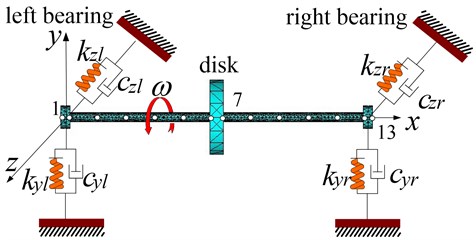
Table 1Coefficients of each shaft segment unit of the rotor system
Shaft segment | 1 | 2 | 3 | 4 | 5 | 6 | 7 | 8 | 9 | 10 | 11 | 12 | 13 |
Length (mm) | 15 | 40 | 40 | 40 | 40 | 40 | 20 | 40 | 40 | 40 | 40 | 40 | 15 |
Diameter (mm) | 10 | 10 | 10 | 10 | 10 | 10 | 60 | 10 | 10 | 10 | 10 | 10 | 10 |
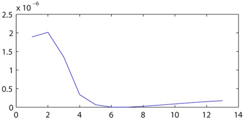
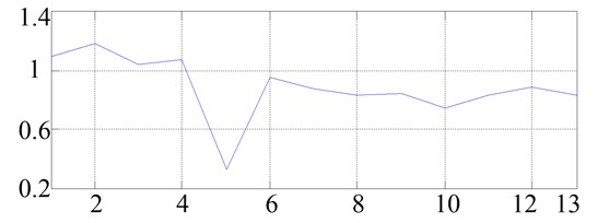
The open crack’s flexibility coefficient do not vary as the rotation angle does and there is only 1X frequency in its response, so we need Eq. (9), i.e. residual dynamic equation, to determine the position of the crack. Assume that the crack is at the center of the 6th segment and the dimensionless crack depth is 0.5. We first get the displacements of nodes 4 and 11 in and direction and that of the node 5 in y direction, and by Eq. (19) we can get the value of of each segment. As shown in Fig. 4, the crack happens where the value of is the smallest, which indicates that the crack happens at segment 6.
Fig. 4Determination of the position of the crack
After that, by obtaining the responses at the two ends of the cracked shaft segment of the rotor system at the rotating speed of 6000 rpm and 6600 rpm, we can get from Eq. (24) , , , and and their dimensionless crack depth , , , and , as shown in Table 2.
Table 2Flexibility coefficient of the crack
0.2575 | 0.3224 | 0.3872 | 1.3716 | 3.8327 |
0.51 | 0.56 | 0.5 | 0.48 | 0.49 |
By averaging , , , and we get the dimensionless crack depth 0.508, which differs slightly from the default value 0.5. Referring to the dimensionless form of the Eq. (3), with the radius of the shaft being 5 mm, we can determine that the actual crack depth is 2.54 mm.
6. Test of robustness
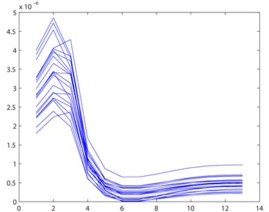
The structure of the rotor system is shown in Fig. 3. And the coefficient of each shaft segment unit of the rotor system is shown in Table 1. Assume that the crack was at the center of the 6th segment and the dimensionless crack depth was 0.5 equally. And due to the influence of the noise, assumed that higher harmonic response [19-21] of the measured signal followed normal distribution, its variance was 0.05. Thus, the 20 times simulations were done. And the result is shown in Fig. 5. Can be seen from the diagram, the crack location was diagnosed in the 6th segment by the method every time.
Fig. 5Result of robustness test
And then, by obtaining the responses at the two ends of the cracked shaft segment of the rotor system at the rotating speed of 6000 rpm and 6600 rpm, we can get the average value of , , , , and their dimensionless crack depth , , , and , as shown in Table 3.
Table 3Robustness test of the crack depth
0.2652 | 0.3143 | 0.3788 | 1.5215 | 3.8983 |
0.52 | 0.55 | 0.49 | 0.52 | 0.53 |
So we get the dimensionless crack depth 0.522. The set value is 0.5. The error is within 5 %. Error rate is small. Can be seen from the above analysis, the method has good robustness.
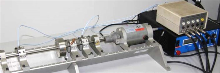
7. Experiment verification
This experiment performs on the Bently rotor test-bed as shown in Fig. 6. The shaft of the rotor system is 450 mm in length and the coefficients of each segment unit are shown in Table 1. There is a crack of 3 mm in depth at segment unit 5. The displacement sensor is installed at node 5 (135 mm from the initial end of the coupling) and node 11 (355 mm from the initial end of the coupling). Use B&K3560B acquisition instrument to collect, filter, magnify and A/D transfer, the sampling frequency being 3.2 kHz.
Fig. 6Bently rotor test-bed
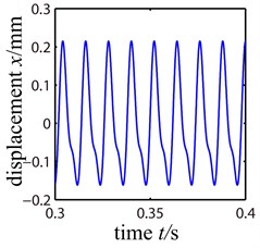
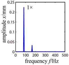
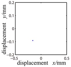
Collect displacements of node 5 and 11 in and direction with rotating speed being 5000 rpm and 5500 rpm respectively. Fig. 7 shows the time-domain waveform, frequency spectrogram and Poincare sectional drawing at node 5 of the cracked rotor system.
Fig. 7Response of the cracked rotor system
a)
b)
c)
We can see that the rotor system performs cycle 1 motion in the Poincare section. And the frequency spectrogram shows that it is mainly working frequency when 2 frequencies seldom appears. Thus we still use the residual vibration quantity equation as the method to extract the crack’s position and use Eq. (19) to obtain the value of of each segment. As shown in Fig. 8, the crack appears at segment 5 where takes on its smallest value.
Fig. 8Determination of the position of the crack
Then we measure the response of the two ends of segment 5 (node 5 and 6) when the rotating speed is at 5000 rpm and 5500 rpm respectively. By Eq. (24) we get 0.4059, 0.5050, 0.7755, 2.4056 and 5.9346, as shown in Table 4.
Table 4Flexibility coefficient and dimensionless crack depth of the crack
0.4059 | 0.5050 | 0.7755 | 2.4056 | 5.9346 |
0.621 | 0.643 | 0.636 | 0.617 | 0.598 |
Combining with Eq. (3) we get the dimensionless crack depth as 0.623, and then we get the actual depth of the crack as 3.115 mm. The extracted position of the crack and its depth (3 mm) are in line with the actual situation.
8. Discussion
The limit of the method:
1) This method needs to obtain the system frequency response function matrix in advance through the structural parameters or the experimental test.
2) If there is not the steady-state period response caused by strong nonlinear such as quasi-periodic, chaotic and so on in the rotor system, the method is ineffective.
The advantages of this method:
1) This method will be able to identify the location of the crack through the only two positions of vibration response. Due to the sensors can be only placed in the bearing displacement of the large rotating machinery, this method is applicable.
2) This method is not only effective for piecewise linear local nonlinear system, but also for other types of local nonlinear in the engineering. As long as it can be fitted to a polynomial form, this method can be used to identify the local nonlinear position.
9. Conclusion
1) Based on crack flexibility matrix, the dynamic model and residual dynamic model of the cracked rotor system were established in this paper. By analyzing the stress conditions of the two ends of the cracked shaft segment and combining the residual quantity dynamic equation, it provides a method by which information about the open crack’s position and its depth can be extracted from the vibration signals of the rotor system.
2) The information extracting method put forward by this paper can be used to diagnose open crack fault, as of rotor system, cantilever beam or truss structure. The method needs to collect the vibration signals of three nodes at two different rotating speeds, which is easy and feasible.
3) For a real-life industrial environment, this method remains to be tested. But in the theoretical point of view, the method is feasible.
References
-
Dimarogonas A. D.,Papadopoulos C. A. Vibration of cracked shafts in bending. Journal of Sound and Vibration, Vol. 91, Issue 4, 1983, p. 583-593.
-
Gounaris G.,Dimarogonas A. D. A finite element of a cracked prismatic beam in structural analysis. Comput. Struct., Vol. 28, 1988, p. 309-313.
-
Zheng Jibing, Meng Guang The nonlinear influences of whirl speed on bifurcation and chaos of a cracked rotor. Journal of Vibration Engineering, Vol. 10, Issue 2, 1997, p. 190-197, (in Chinese).
-
Darpe A. K.,Gupta K.,Chawla A. Coupled bending, longitudinal and torsional vibrations of a cracked rotor. Journal of Sound and Vibration, Vol. 269, Issue 1-2, 2004, p. 33-60.
-
Tada H.,Paris P. C.,Irwin G. R. The stress analysis of cracks handbook. Hellertown, Pensylvania, Del Research Corp, USA, 1973.
-
Papadopoulos C. A.,Dimarogonas A. D. Coupled longitudinal and bending vibration of rotating shaft with an open crack. Journal of Sound and Vibration, Vol. 117, 1987, p. 81-93.
-
Sekhar A. S. Crack detection and monitoring in a rotor supported on fluid film bearings: start-up vs run-down. Mechanical Systems and Signal Processing, Vol. 17, Issue 4, 2003, p. 897-901.
-
Sekhar A. S., Mohanty A. R., Prabhakar S. Vibrations of cracked rotor system: transverse crack versus slant crack. Journal of Sound and Vibration, Vol. 279, Issue 3-5, 2005, p. 1203-1217.
-
Gasch R. Dynamic behaviour of the Laval rotor with a transverse crack. Mechanical Systems and Signal Processing, Vol. 22, Issue 4, 2008, p. 790-804.
-
Bachshmid N.,Pennacchi P.,Vania A. Identification of multiple faults in rotor systems. Journal of Sound and Vibration, Vol. 254, Issue 2, 2002, p. 327-366.
-
Saavedra P. N.,Cuitino L. A. Crack detection and vibration behavior of cracked beams. Computers and Structures, Vol. 79, 2001, p. 1451-1459.
-
Sawicki J. T. Rotor crack detection using active magnetic bearings. Diffusion and Defect Data Part B, Solid State Phenomena, Vol. 144, Issue 2, 2009, p. 9-15.
-
Chan F. W. Y. Reflective fringe pattern technique for subsurface crack detection. NDT&E International, Vol. 41, Issue 8, 2008, p. 602-610.
-
Green I., Casey C. Crack detection in a rotor dynamic system by vibration monitoring – Part I: analysis. Journal of Engineering for Gas Turbines and Power, Vol. 127, Issue 2, 2005, p. 425-436.
-
Saavedra P. N., Cuitno L. A. Vibration analysis of rotor for crack identification. Journal of Vibration and Control, Vol. 8, Issue 1, 2002, p. 51-67.
-
Xie Ping, Du Yihao Crack rotor dynamic feature analysis and diagnosis method based on information entropy. Journal of Mechanical Engineering, Vol. 45, Issue 1, 2009, p. 195-199, (in Chinese).
-
Ramesh B. T., Srikanth S., Sekhar A. S. Hilbert-Huang transform for detection and monitoring of crack in a transient rotor. Mechanical Systems and Signal Processing, Vol. 22, Issue 4, 2008, p. 905-914.
-
Chondros T. G.,Dimarogonas A. D.,Yao J. Vibration of a beam with a breathing crack. Journal of Sound and Vibration, Vol. 239, Issue 1, 2001, p. 57-67.
-
Kulesza Zbigniew, Sawicki Jerzy T. Auxiliary state variables for rotor crack detection. Journal of Vibration and Control, Vol. 17, Issue 6, 2011, p. 857-872.
-
Sun Xiaoming, Huang Jianping, Liu Wanyu Decision model in the laser scanning system for pavement crack detection. Optical Engineering, Vol. 50, Issue 12, 2011, p. 127-207.
-
Amstutz S. L., Horchani I., Masmoudi M. Crack detection by the topological gradient method. Control and Cybernetics, Vol. 34, Issue 1, 2005, p. 81-101.
About this article

This work was financially supported by the National Natural Science Foundation of China for Young Scientists (Grant No. 51105065), Exploration-oriented Key Scientific and Technological Innovation Project from Ministry of Education of China (Grant No. N110203001), National Science Foundation for Postdoctoral Scientists of China (2013M541239, 2014M551105).
