Abstract
The existence of various types of joints, one of the typical characteristics of prefabricated lining structures, makes the mechanical performance of shield tunnel linings quite different from that of monolithic linings. A simplified calculation method for the dynamic elastic-plastic analysis of segment lining subjected to explosive loads is proposed. The lining is composed of a number of rigid arch segments that are interconnected by elastic-plastic hinges. The dynamic interaction between the segments and the bolts, and the interaction between tunnel lining segment and soil-structure can be properly simulated with the method. As an example, the calculation of the shield section of Nanjing metro subjected to blast loading was discussed. The time-history curves of displacement and speed of some key points of section lining were obtained. Furthermore, the influences of rock grade and joint stiffness on dynamic response of tunnel lining were taken into account. The result indicates that the simplified method of blasting response analysis can reflect the response of structure subjected to blast loading accurately. The results will be a reference for antiknock analysis and design of tunnel lining.
1. Introduction
The shield tunnel is becoming more and more popular because of its virtues such as saving underground space, making the planning of the underground space more flexible and so on. Static data shows that for more than 60 percent of the terrorists’ attacks on the subway belong to bombings attacks, therefore to carry out anti-terrorist bombings research and evaluation work of shield tunnel linings has very important practical significance.
Designers are often concerned with the dynamic response of shield tunnel linings under external impact loads. In many cases, this problem is commonly simplified and non-joint-considered of segments lining [1-6]. The errors will be large for the exact analysis of dynamic response of segments lining structure itself if the segments lining is regarded as a whole tube body with non-joint-considered, so the joints should be considered for segments lining structure analysis. Yankelevsky et al. [7] analyzed the large dynamic elastic-plastic deflections of a multi-segmented spring-supported prefabricated circular lining, and provider a numerical solution for both the uniform and the non-uniform base. The stress and deformation state of the segment structure and the surrounding medium under initial stress field is essential in solving response to the damage of tunnel segment structure, directly affect carrying capacity of tunnel segment structure to the explosion. Yuetang Zhao et al. [8] investigated the initial stress and strain state of subway segmented tunnel by LS-DYNA, and compared the initial states at different buried depths. Considering the reinforcement of bolt in the surrounding media, Wang Yong et al. [9] studied the dynamic response of section subway tunnel under different yields of surface explosion for evaluation the blast-induced effects by using LS-DYNA. The numerical results indicated that the top part and the center at the bottom of the section subway tunnel were more damaged zones, and the section subway tunnel was safe when 100 kg TNT detonates at the height of 1.5 m.
In this paper, the deformability of the segments is disregarded and the segments are assumed to be rigid body. Considering the initial segment of static state of the structure, an analytical solution for dynamic response of shield tunnel segment under explosive loads is presented. Based on a certain tunnel project, the numerical simulation method is used to verify the reliability and effectively of the analytical solution.
2. The model
The design method proposed is based on lumped mass model of soil-structure dynamic interaction system, by including several additional features. It considers soil and segment interaction and focuses on each joint’s forces. The proposed model is assumed to be composed of rigid arch segments interconnected by elastic-plastic joints. The surrounded medium is simulated by visco-elastic base. The problem is reduced to a system of nonlinear algebraic and differential equations which are solved by the direct step-by-step differentiation method with a stepwise check of the state of every joint.
Fig. 1Sketch of simulated condition
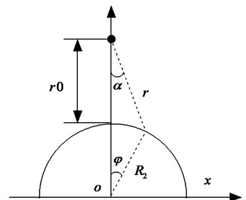
Prediction of particle displacement, velocity, acceleration, pressure and other parameters in the earth media resulting from an explosive detonation is a complicated and difficult task. Primary guidance on this topic is from the United States Department of the Army Technical Manual “Fundamental of Protective Design for Conventional Weapons”, TM5-855-1 [10]. A circular lining under top explosion (Fig. 1) is considered. The peak values of free-field stress is given as:
where is the peak pressure; is ground coupling factor; is a constant; is acoustic impedance; is the distance to the explosion; is charge weight; is attenuation coefficient; is the elapsed time from the instant of detonation to the time at which the ground shock arrives at a given location; is equivalent blast duration.
The outer surface of shield tunnel lining at any point, the load time of arrival time of the peak pressure and pressure are different, the peak stress distribution along the lining surface expression [11] is:
where is the attenuation coefficient; is the lateral pressure coefficient; is the general reflection coefficient and defined as follows:
where is the positive reflection coefficient; the incident angle and are shown in Fig. 1. The pressure acting on the segment lining at any point can be expressed as:
where is the pulse duration.
3. Equations of motion
3.1. Initial static analysis
The stress and deformation state of the segment structure and the surrounding medium under the initial stress field is essential in solving response to the damage of tunnel segment structure, which directly affects carrying capacity of tunnel segment structure to the explosion. In many cases, the deformation of the lining has already appeared before the external load acted on the structure or the ground has already subjected to relatively high initial stresses. So the initial stresses of considerable magnitude have to be considered as a starting point in structural engineering.
Fig. 2The segment static loading system
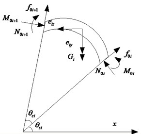
For prefabricated linings, the strain of the joints interconnecting the different segments is usually considerably lower than the limited state. In such cases, the skin friction of circumferential bolts may be disregarded. The initial static loading system acting on a single segment is shown in Fig. 2. According to the geometrical relationship, corresponding constants under the case can be derived as:
where is the central angle; is the polar coordinate of the segment point with respect to the horizontal direction; is the centre radius; is the circumferential pressure; is the pre-load modeling on bolts; is the self-weight of the tunnel lining; , are and projections of the overburden soil pressure; is the static friction, which relies on as:
where is the static friction coefficient; which depends on the soil properties and represents its shear stiffness.
Fig. 3Bilinear stiffness model
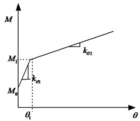
The bending moment in the hinge depends on the relative angular rotation of the connected segments. The analysis model in this study is in a manner similar to the bilinear stiffness model by Zhu Wei [12]. The bending moment can be defined as (Fig. 3):
where is the segment joint bending stiffness, which is defined by the result of the experiment; is the ultimate moment at the joint; is the turning point moment. These terms depend on the axial force as follows:
where , , are the unknown coefficients, that depend on the test data of load cushion, water-proof plastic and pretightening force of bolts.
3.2. Equations under explosive load
The loading system acting on a single segment is shown in Fig. 4. Here is the blast load; is the interaction force between longitudinal segments and is defined as follows:
where is the axial displacement under static equilibrium; is the shear stiffness; is the axial displacement under dynamic load which can be defined as .
The forces of interaction between the segments and bolts are defined as:
where is the shear modulus of the bolt, is the cross-section area, is the shear deformation.
Fig. 4The segment loading system
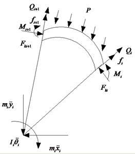
The sliding friction force on the lining simulating the normal and tangential reactions is determined by formula:
where is the dynamic friction coefficient.
According to the geometrical relationship in Fig. 4, the resultant of the external force with respect to lining actions per unit area of square action, as follows: , are and projections of the resultant forces; is the resultant moment with respect to the lining center, are given in the form:
where .
The final system of equations of motion is obtained in the following form:
where is the mass moment of inertia of the segment with respect to its instantaneous center; , are the displacements of the segment with respect to a Eulerian Cartesian coordinate system , and is the segment’s angular rotation with respect to its instantaneous center.
3.3. Unloading stage
Segment will cause deformation under load, and rebound deformation will occur when unloading. The segment will bears active soil pressure, and the friction between segments will decrease. The sliding friction force on the lining can be expressed as:
The total pressure at unloading stage is similar to that of initial stage. The complete system of equation for the solution of the problem includes the equations of motion (13) and the initial conditions (5) that are dependent on the static solution.
4. Comparison of analytical solution and numerical modeling
The finite element method is a well-recognized numerical tool to analyze geotechnical works because its ability to take into account the non-behavior of soils and the complex geometry of the works. To verify the proposed analytical solution, analysis has been performed using LS-DYNA. In the model, each segmental lining is modeled by a mesh of three-dimensional shell elements, and the segmental joint element is used to simulate the joints between the segmental linings. The contacts between the segments and bolts, and the contacts between tunnel lining segment and soil, reinforced concrete coupling, transmitting boundary setting are also considered.
An application example of the tunnel linings for the first stage of Nanjing subway project is presented. Fig. 5 shows the layout of segment joints which was constructed in the clay deposit. The inside diameter and width of the tunnel linings are 5.5 m and 1.2 m, respectively. The linings were constructed by C50 concrete. The Young’s modulus of concrete is 3.45×10⁴ N/mm2 (see Table 1). The blast wave is generated by an explosion of an explosive-line charge of 5 kg TNT dynamite.
Fig. 5Layout of segment joints
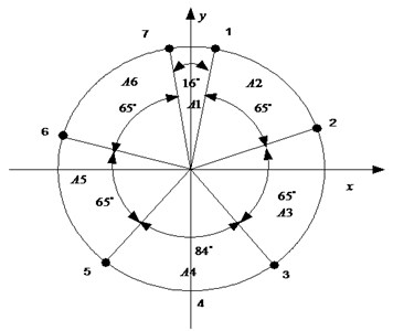
Table 1Model parameters in numerical simulation
Lining | Soil | Segment joint | |||
3.45×10⁴ MPa | 17.4 kN/m3 | 3.45×10⁴ N·m/rad | |||
0.2 | 9 kpa | ||||
0.35 m | 29.1° | 3.93×10¹⁰ N/m | |||
6.2 m | 10000 kN/m3 | ||||
1.2 m | 0.45 | ||||
Fig. 6(a) and (b) shows the results of the time history of the cover velocity and displacement from analytical method in comparison with those obtained from numerical solution. As can be seen in the figure, the prediction of the current model agrees well with the numerical result. On the whole, compared with analytical solution result, the maximum of velocity conducted by the numerical modeling is small, while the maximum of displacement is large, the major cause of this deviation is that the two computational models, the deformability of the segments is disregarded and the segment is assumed to be rigid body in the deduction of analytical solution.
Fig. 6The comparison by two kinds of solving methods
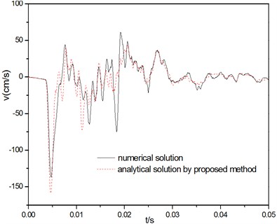
a) Velocity response
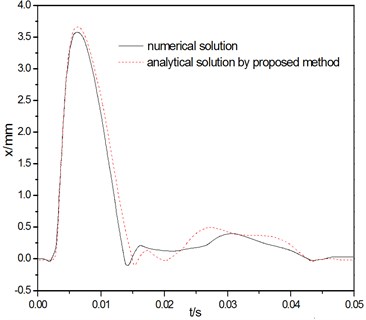
b) Relative displacement of segment joint
5. Parametric studies
5.1. Influence of rock grade
The conceptions of impedance ration and flexibility ratio (A detailed description is given in Peck [13]) are presented to analyze the influence of surrounding rock mass character, they are defined as follows:
where , , are the Young’s modulus, Poisson’s ratio and mass density of soil; , , are the Young’s modulus, Poisson’s ratio and mass density of the lining structure; is the lining’s mean radius; is the lining’s thickness. Physical properties of soil layers are shown in Table 2.
Table 2Physical properties of soil layers
Soil | kg/m3 | MPa | m/s | |||
I | 1700 | 63.7 | 0.3 | 120 | 1.59 | 0.035 |
II | 1800 | 292.5 | 0.3 | 250 | 7.31 | 0.078 |
III | 1900 | 605.2 | 0.3 | 350 | 15.12 | 0.115 |
IV | 1900 | 1000.4 | 0.3 | 450 | 25 | 0.148 |
I: soft ground, II: medium soft soil, III: medium hard soil 1, IV: medium hard soil 2 | ||||||
The corresponding response of acoustic impedance and flexibility ratio is given in Figs. 7. These figures show that, the peak values of liner displacement and bending moment decrease as the acoustic impedance and flexibility ratio increase, while the ascending time decreases, the loading frequency increased and the vibration characteristics is enhanced. The peak values of displacement of bending moment change significantly when the value of flexibility ratio range between 1.59 and 15.12, acoustic impedance increases from 0.035 to 0.115, while when the flexibility ratio increases to 25, the change becomes gently. This conclusion has a good agreement with the qualitative result from the valuating criteria of relative flexibility founded by Peck. This implies that the strengthening of ground stiffness will result in reduction of the additional deformation and bending moment in cross section of tunnel. Its effect is especially significant for low flexibility ratio. The condition of surrounding rock is the important factor affecting the internal force of tunnel liner caused by explosion seismic wave. The worse surrounding rock conditions are, the more remarkable internal force caused by seismic wave produce and the worse explosive resistance performance represent. Engineering design and construction should avoid the impact of adverse geological and select characteristics of a good formation.
Fig. 7Influence of rock grade
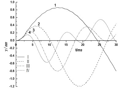
a) Displacement of liner top
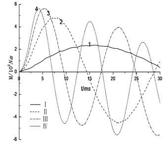
b) Bending moment of liner top
5.2. Influence of joint stiffness
Segment joint stiffness is an important parameter for the design of shield tunnel segment. Fig. 8 shows the influence with different joint stiffness of 2000, 4000 and 6000 N∙m/rad. It can be observed that as the joint stiffness increases, the liner top displacement amplitudes decrease gradually, but the bending moment amplitudes increase. It can also be found that the influence of joint stiffness on the displacement is minor while that on the bending moment is great and cannot be ignored. This result agrees with the investigative result proposed by Okamoto.
Fig. 8Influence of joint stiffness
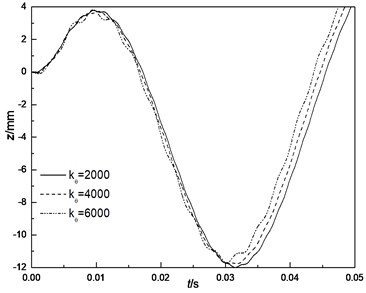
a) Displacement of liner top
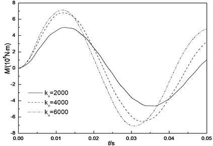
b) Bending moment of liner top
6. Conclusions
Deformation and damage of tunnel lining under the load of terrorist bombing is one of major security issues. In this study, dynamic response of shield tunnel segment subjected to explosive loads is analyzed. The main results obtained from the study are as follows.
(1) An analytical solution to the dynamic response of shield tunnel segment lining has been developed. It is relatively simple yet comprehensive enough to consider several parameters and physical mechanisms that are pertinent to the current problem. The contacts between the segments and bolts, as well as the contacts between tunnel lining segment and soil are considered.
(2) In order to verify the reliability of the proposed method, comparison with the numerical calculation is performed, and the results show good correspondence.
(3) In combination with project practice, the influence of the rock grade and joint stiffness of the segment are analyzed. The results show that the higher the surrounding rock grade, the better the capacity to resist deformation of liner structure and the better the blast-resistant characteristics of the tunnel will be; the joint stiffness has obviously impact to bend of structure and has lightly influence to displacement. For this reason, it has distinct influence to safety factor too.
References
-
Kong De-Sen, Meng Qing-Hui, Zhang Wei-Wei, et al. Shock responses of a metro tunnel subjected to explosive loads. Journal of Vibration and Shock, Vol. 12, Issue 31, 2012, p. 68-72.
-
Liu Qi-Jian, Zhao Yue-Yu Dynamic stability of circular tunnel linings subjected to radial harmonic excitation. Journal of Hunan University, Natural Science, Vol. 38, Issue 9, 2011, p. 22-26.
-
Liu Mu-Yu, Lu Zhi-Fang Analysis of dynamic response of Yangtze river tunnel subjected to contact explosion loading. Journal of Wuhan University of Technology, Vol. 29, Issue 1, 2007, p. 113-117.
-
Ma Li-Qiu, Zhang Jian-Min, Zhang Ga, et al. Research of blasting centrifugal modeling system and basic experiment. Rock and Soil Mechanics, Vol. 32, Issue 3, 2011, p. 946-950.
-
Ma Liqiu, Zhang Jian-Min, Hu Yun, et al. Centrifugal model tests for responses of shallow-buried underground structures under surface blasting. Chinese Journal of Rock Mechanics and Engineering, Vol. 29, Issue 2, 2010, p. 3672-3678.
-
Liu Gan-Bin, Zheng Rong-Yue, Zhou Ye Numerical model for dynamic response of tunnel in clay. Journal of Ningbo University, Vol. 22, Issue 2, 2009, p. 263-267.
-
Karinski Y. S., Yankelevsky D. Z. Dynamic analysis of an elastic-plastic multisegment lining buried in soil. Engineering Structures, Vol. 29, Issue 1, 2007, p. 317-328.
-
Luo Kun-Sheng, Zhao Yue-Tang, Luo Zhong-Xing, et al. Numerical simulation on initial stress and strain state of subway segmented tunnel. China Civil Engineering Journal, Vol. 46, Issue 4, 2013, p. 78-84.
-
Luo Kun-Sheng, Wang Yong, Zhao Yue-Tang, etal. Numerical simulation of section subway tunnel under surface explosion. Journal of PLA University of Science and Technology, Vol. 8, Issue 6, 2007, p. 674-679.
-
TM5-855-1. Fundamentals of protective design for conventional weapons. Vicksburg, US army engineers waterways experimental station, 1986.
-
Jin Feng-Nian, Yuan Xiao-Jun, Zhou Jian-Nan, et al. Distribution law of blast loads on large-span compound structure. Journal of PLA University of Science and Technology, Vol. 12, Issue 6, 2011, p. 635-642
-
Zhu Wei, Zhong Xiao-Chun, Qin Jian-She Mechanical analysis of segment joint of shield tunnel and research on bilinear joint stiffness model. Rock and Soil Mechanics, Vol. 27, Issue 12, 2006, p. 2155-2158.
-
Peck R. B., Hendron A. J., Mohraz B. State of the art of soft ground tunneling. Proceedings of the Rapid Excavation and Tunneling Conference, Chicago, 1972.
About this article

This work is substantially supported by National Basic Research Program of China (973 Program: 2010CB732003, 2013CB036005), National Natural Science Foundation of China (No. 51308542, 50878208).
