Abstract
Aiming at the problems, bad low velocity performance and slow response, existing in variable speed hydraulic systems, this study proposes a variable speed hydraulic system in valve-pump parallel variable structure control, in which control structures vary with control requirement. The leaking parallel valve control is applied to improve low-speed performance at the start and stop stages by increasing damping ratios and compensating the reduction of damping ratios due to the friction negative slop; the replenishing parallel valve control is applied to achieve fast response to load disturbance at the uniform stage with high speed; the variable speed pump control is to make full use its high efficiency at other stages. During the regulation process, these control structures switch smoothly and a good speed tracking is achieved, in addition, the pump provides majority of required flow, so the proposed system still can work efficiently as pump control systems. Therefore, the valve-pump parallel variable structure control establishes a flexible control mechanism by two channels of valve control and pump control, and could improve comprehensive performances of variable speed hydraulic systems with large power, such as low-speed performance, rapid response and high efficiency.
1. Introduction
The variable speed hydraulic system is a new kind of overall energy-saving system, which usually utilizes a variable speed pump, a fixed displacement pump driven by a variable speed electric motor, and controlling the rotary speed of the electric motor will regulates the discharge flow of the pump and varies the output of actuators. Compared with traditional variable displacement hydraulic systems, utilizing the form of a constant speed electric motor driving a variable displacement pump [1-3], variable speed hydraulic systems have many advantages, such as higher reliability, wider range of speed regulation, better energy-saving, and lower cost [4-6].
However, variable speed hydraulic systems still own some drawbacks as follows. (1) Bad low-speed performance with severe pressure impact. Hydraulic pumps can't works below the minimum stable speed, or it will cause severe flow and pressure ripple; moreover, the electric motor also can’t supply adequate torque to control the pump under comparatively low frequency, especially at start and stop. (2) Slow response. Duration of acceleration and deceleration of electric motor are very relatively long due to limitation of overload capacity of inverter and large inertia of electric motor and pump, these result in slow response.
To solve above disadvantages, a flow valve is commonly connected to the variable speed pump in series, to form a valve-pump series variable speed hydraulic system [7-8]. In this kind of system, at low-speed stage and decelerating stage, the valve controls system flow to improve low-speed performance and decelerating response; at other stages, the valve opens completely and the system is controlled by the pump. However this compound system responds slowly at accelerating stage due to lack of enough flow. To solve this problem, an energy regulation device is added on above system, and forms an energy-regulation variable speed hydraulic system [8-10]. The energy regulation device can absorb redundant oil fluid during deceleration period and release oil flow during acceleration period. However above valve-pump series systems are not suitable to large power systems, because the flow valve connected to system main circuit in series limits the maximum system flow.
Valve-pump parallel hydraulic control systems are preferable large power systems, in which the flow valve is connected to the pump in parallel. So far, the valve-pump parallel control mainly focuses on electrical hydraulic actuators of fighters [11-13]. In above parallel control systems, both the valve and variable speed pump supply flow to the actuator, and total system flow is the sum of valve flow and pump flow, so the valve-pump parallel control only can improve to system response characteristics but makes the problem of low-speed performance worse [14].
We present a new type of variable speed hydraulic system in valve-pump parallel variable structure control, where a flow valve is parallel to a variable speed pump and could work at leaking status and replenishing status, and its control structure can vary with control requirements during the regulation process. This paper first designs the proposed system and then builds its mathematical model, analyses dynamic performances by simulation on AMESim platform at the end.
2. System design
2.1. Operating principle
The Schematic framework of the variable speed hydraulic system in valve-pump parallel variable structure control is shown in Fig. 1, which is an open cycle system. The fixed displacement pump is driven by the variable frequency motor, and regulating output frequency of the inverter will vary pump speed and then adjust pump output flow.The servo-proportional direction valve (SPDV) is coupled to the forward chamber in parallel to drive the hydraulic motor with the variable speed pump. The solenoid directional valve is used to change the rotary direction of hydraulic motor. The system is loaded by the loading pump and the load pressure is regulated by the proportional relief valve. The hydraulic motor speed is measured and fed back to the controller via the encoder, then is compared with the reference signal and the error is corrected, and the controller outputs two control signals, one is to inverter to vary electric motor speed, and another is to SPDV to control its opening.
Fig. 1Schematic framework of the proposed system. 1 – Inverter; 2 – Variable frequency motor; 3 – Fixed displacement pump; 4 – SPDV; 5 – Solenoid directional valve; 6 – Hydraulic motor; 7 – Inertia; 8 – Encoder; 9 – Loading pump; 10 – Proportional relief valve; 11 – Loading system; 12 – Oil source of SPDV
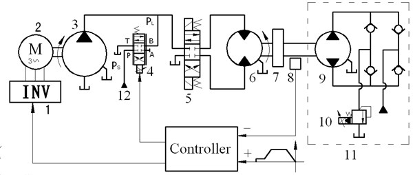
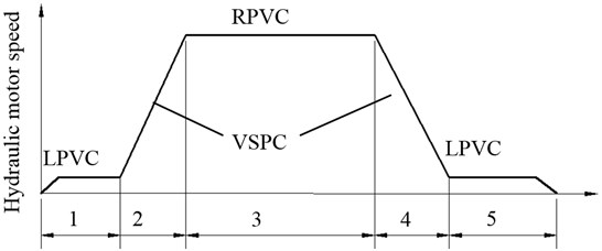
Fig. 2 shows the it’s principle in a duty circle.
1) At the start and stop stages with low speed, the system is under the leaking parallel valve control (LPVC) mode. At the start stage, the pump works at an initial speed, which is above its minimum stable speed, and discharges a certain amount of flow, and SPDV with a pre-opening at the very beginning is given negative currents all along, which makes port links with port (oil tank) to form a bypass leakage passage to improve low-speed performance of hydraulic motor. Hydraulic motor speed increases with the decrease of SPDV’s opening, and then reaches a stable speed when SPDV is totally closed. SPDV goes by contraries at the stop stage.
2) At the accelerating and decelerating stages, the system is under variable speed pump control (VSPC) mode, and hydraulic motor speed varies with pump speed which is above the initial speed.
3) At the uniform stage with high speed, the system is under the replenishing parallel valve control (RPVC) mode. At this stage, the pump with a fixed speed discharges a certain fluid flow, which is less than the flow required by desired speed of hydraulic motor, and SPDV is given positive currents all along, and port links with port to compensate fluid to forward chamber to improve response to load variation.
Fig. 2Speed regulation process in a duty circle. 1 – Start; 2 – Acceleration; 3 – Uniform; 4 – Deceleration; 5 – Stop
Therefore, here “variable structure” means that system control structure (mode) varies with control requirements at different regulation stages, which can make the most of advantages of variable speed pump control and valve control to achieve comprehensive performances, such as low speed performance, rapid response to load variation as well as high efficiency.
(Note: for enhancing readability, the variable speed pump control, leaking parallel valve control and replenishing parallel valve control are referred to as pump control, leaking control and replenishing control for short in the following paper, respectively).
2.2. System configuration
Key components are selected according to above principle, as shown in Table 1. The Inverter is a vector inverter, and the pump is a bend axis type of fixed displacement pump with small displacement and high speed, its minimum stable speed is 500 r/min. The hydraulic motor is inner curved type with large displacement and low speed, and its maximum speed is 90 r/min. The loading pump has the same parameters as hydraulic motor. The rated flow of SPDV is selected to 9 L/min according to 6 L/min corresponding to minimum stable speed of the pump.
Table 1Parameters of key components
Components | Specification | Components | Specification |
Electric motor | power: 7.5 kW; rated speed: 3000 r/min | Inverter | power:11 kW with vector control; frequency range: 0.1-400 Hz |
SPDV | rate flow: 9 L/min at 1.5 MPa per notch; max current: 40 mA; frequency: 60 Hz; damping ratio: 0.7 | Hydraulic motor and loading pump | speed range: 0-90 r/min; displacement: 468 mL/r; rated pressure: 40 MPa |
Pump | displacement:12 ml/r; speed range: 500-3000 r/min | Proportional relief valve | pressure range: 0.7-31.5 MPa; rate flow: 200 L/min |
Inertia | 70 gm2 |
3. Mathematical modelling
3.1. Variable speed pump link
Since the dynamic of invent is fast enough to be neglected, the inverter is assumed to be a proportional element, that is:
where is frequency gain of inverter, is input voltage of inverter, is output frequency of inverter.
Electromagnetic torque of electric motor is:
where , is phase voltage of stator, and 4.4 is gain from frequency to voltage, , , and 1 is the number of pole pair, 0.436 Ω is resistance of rotor side referred to stator, is actual angular velocity of electric motor.
Torque balance equation is:
where is load torque, and is system pressure (actually, output pressure of the pump), is displacement of the pump, is total inertia referred to motor shaft, roughly equal to 0.2 kg/m2, is total viscous damping coefficient, about 0.01 Nms/rad.
Eqs. (1)-(3) can be combined and Laplace transformed to yield:
where , , , and actual rotary speed of electric motor is . This transfer function indicates that the inverter-motor is a first-order inertia element, and electric motor speed increases with increasing input voltage and decreasing system pressure . Hence the actual flow of the variable speed pump is:
where is unload flow of the variable speed pump and is total leakage coefficient of the pump.
3.2. Valve control link
Under the leaking control mode, the bypass valve SPDV works at leaking status and its flow equation is given by:
where is input current of SPDV at leaking status, is the constant of SPDV, and are hydraulic natural frequency and damping ratio of SPDV, respectively, and are actual flow of SPDV at leaking status, respectively, and are flow gain and flow-pressure coefficient of SPDV at leaking status, respectively.
Under the replenishing control mode, SPDV works at replenishing status and its flow equation is given by:
where is input current of SPDV at replenishing status, and are actual flow and unload flow of SPDV at replenishing status, respectively, and are flow gain and flow-pressure coefficient of SPDV at replenishing status, respectively.
3.3. Hydraulic motor link
Under the leaking control mode, the total system continuity equation is:
Under the replenishing control mode, the total system continuity equation is:
where is leakage coefficient of hydraulic motor, is angular speed of hydraulic motor, is displacement of hydraulic motor, is average volume of forward chamber.
Torque balance equation of hydraulic motor is:
where is total inertia referred to shaft of hydraulic motor, is vicious damping coefficient. is load torque produced by loading pump without consideration of pressure of return chamber, and is displacement of loading pump.
Combing Eqs. (5), (6), (8) and (10), the open loop dynamic equation of the proposed system in leaking control is:
where , , . is total leakage coefficient of the proposed system under the leaking control mode, and is natural frequency and damping ratio of the proposed system the leaking control mode, respectively.
Combing Eqs. (5), (7), (8) and (9), the open loop dynamic equation of the proposed system under the replenishing control mode is:
where , , . is total leakage coefficient of the proposed system under the replenishing mode, and are natural frequency and damping ratio of the proposed system under the replenishing mode, respectively.
The valve-pump parallel control will switch to the only pump control when SPDV is closed, and , , and will be zero in Eqs. (11), (12), so the open loop dynamic equation of the proposed system under the pump control mode is given by [15-16]:
where , , . is total leakage flow of pump and motor, is total leakage coefficient of the proposed system under the pump control mode, and are hydraulic natural frequency and damping ratio of the proposed system under the pump control mode, respectively.
We note that Eqs. (11)-(13) are similar, so the pump control mode can be regarded as a special case of valve-pump parallel control mode.
The rotary encoder responds fast and could be regarded as a proportional element:
where is feedback gain and is feedback voltage of encoder, and is rotary speed of motor.
3.4. Total system mathematical model
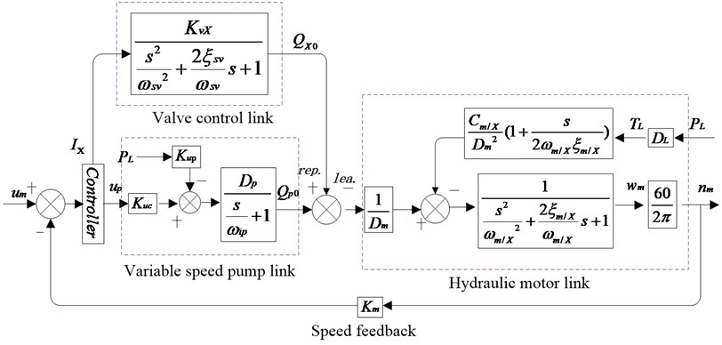
Fig. 3 shows the control block diagram of the proposed system, which is made up of valve control link, variable speed pump link and hydraulic motor link. The control system can work at replenishing parallel valve control mode and leaking parallel valve control mode when SPDV works at leaking status and replenishing status, respectively. The system parameters are list in Table 2.
Table 2Parameters of the total system
Symbol | Value | Unit | Symbol | Value | Unit |
1.0×10⁻³ | m3 | 16.7 | rad /s | ||
70 | kg·m2 | 314 | rad /s | ||
7.45×10⁻⁵ | m3/rad | 0.7 | |||
2.94×10⁻¹² | m3/(s·Pa) | 10.48 | rad /s | ||
1/6 | V·min/r | 0.19 | |||
or | 0.58 | m3/(s·mV) | or | 10.48 | rad/s |
or | ≥2.94×10⁻¹² | m3/(s·Pa) | or | ≥0.19 | |
2.14 | 3.10 | ||||
3.10 |
Fig. 3Block diagram of the proposed system. Subscript “m/X” represents “m or x” and “x” represents “l” and “r” when SPDV works at leaking status and replenishing status, respectively
The uncompensated open loop transfer functions of the proposed system under the pump control mode, leaking control mode, and replenishing control mode, are respectively given by:
It is obvious that these servo loops are type 0 and unstable, which may be corrected internal links (i.e., , and ), respectively. So the compensated open loop transfer functions of the proposed system under the three modes are respectively given by:
where and are internal gains, , are compensated open loop gains of the proposed system under the pump control mode, leaking control mode and replenishing control mode, respectively.
From Table 2, we note , so the hydraulic natural frequency (or or ) is the lowest break frequency and dominates dynamic performances of the total system, so these high frequency loops in Eqs. (18)-(20) can be omitted. According to stable criterion, and for getting appropriate amplitude margin and phase margin, these compensated open loop gains should satisfy following relations: , , . After optimization, we set 1.5, 15, 15. These values are estimated conservatively because of wide variation of damping ratios, increasing these values will improve dynamic response indeed but will bring instability problem.
The static closed loop speed stiffness of the proposed system under the pump control mode is:
The static closed loop speed stiffness of the proposed system under the leaking control mode is:
The static closed loop speed stiffness of the proposed system under the replenishing control mode is:
4. Dynamic characteristics analysis
4.1. Simulation model
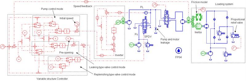
Fig. 4 shows the simulation model of the proposed system set up on the AMESim platform according to the schematic in Fig. 1. AMESim is a professional software used for multidisciplinary simulation in a uniform graphical environment, widely used in the field of automobile, hydraulic servos [17], aerospace engineering, etc. A simulation on AMESim is needed to go through four steps: Sketch→Submodels→Parameters→Simulation.
Key components on AMESim are set as Table 1. FP04 is used to set the characteristics of the hydraulic fluid, in which the effective bulk modulus of fluid is 1400 MPa. To simulate total leakages of pump and motor , a fixed orifice is parallel connected to the high pressure chamber of motor and its characteristic flow rate is set to 0.1 L/min per pressure drop of 0.1 MPa. The rated input of the inverter is 10 V corresponding to maximum speed of eclectic motor, and the rated input of the SPDV is 40 mA and –40 mA corresponding to maximum positive opening and maximum negative opening, respectively. Because the previous pump loading system can’t simulate the friction behavior of hydraulic motor at low speed, a friction model with Stribeck effect [18-19] is added to form a new loading system, so now the load torque should be the sum of friction torque and previous torque produced by loading pump. We build a variable structure controller, which can switch to pump control mode, leaking control mode and replenishing control mode according to control requirements.
Fig. 4Simulation model on AMEsim
4.2. Parameter analysis of total system
This section will observe the influence of valve control on parameters of system in open loop control and Stribeck effect in the friction model is not taken into account for clear observation. For examining the influence in its entirety, here the pump control, leaking control and replenishing control are not targeted at particular regulation stages, which differences to the principle in section 2.
4.2.1. Influence of control signals on system parameters
Referring to Eqs. (11)-(13), the systems in pump control, leaking control and replenishing control share the same hydraulic natural frequencies, i.e., , which is the lowest natural frequency in the overall system and dominates the dynamic performance of the total system. Therefore, we can conclude that introducing valve control to pump control system doesn’t change system natural frequency.
However, the valve control circuit has significant impacts on system total leakage coefficients and damping ratios as shown in Fig. 5, which is tested at 10 MPa. Fig. 5(a) shows control inputs of the variable speed pump and SPDV: at 0-5 s, the input of SPDV is zero and that of the pump is a ramp signal, so the system is in the single pump control; at 5-15 s, keeping the inverter input constant and SPDV is given a ramp signal, hence the system is in valve-pump parallel control; after 15 s, keeping the all inputs constant. Fig. 5(b) and (c) indicate total leakage coefficients in pump control are small and constant and little influenced by the pump inputs, but these in leaking control and replenishing control become greater and increase with the increasing valve inputs. Reasons are as following. Comparing Eqs. (11) and (12) and (13), because of the introduction of valve control, total leakage coefficients in leaking control and in replenishing control increase by a flow-pressure coefficient of SPDV and respectively, that is . The total leakage coefficients of pump and motor are small and constant, whereas and are much greater than and varies widely with valve input and (corresponding to valve opening) according to , .
Fig. 5Influences of variation of pump and valve inputs on total leakage coefficients and damping ratios (PL= 10 MPa)
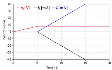
a) Input signal of pump and SPDV
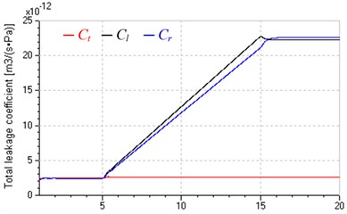
b) Total leakage coefficients
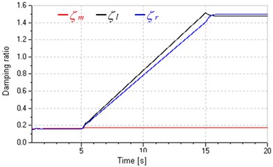
c) Damping ratios
The change of total leakage coefficients caused by valve inputs results in positive and negative influences.
The positive one, damping ratios in valve-pump parallel control increase with total leakage coefficients and become much greater than that in pump control as shown in Fig. 5(c), which will enhance system stability as well as dynamic response by increasing open loop gain and according to the stability criterion , [16].
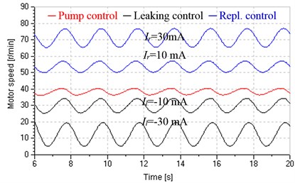
The negative one, Fig. 5(c) also shows that damping ratios vary widely and even exceeds 1; as shown in Fig. 6, hydraulic motor speed fluctuates more widely and is more subject to load variations with the increase of valve input, which indicates that increasing total leakage coefficient will decrease system speed stiffness. Both the wide variation of damping ratios and reduction of speed stiffness will add difficulties in prediction and control for dynamic performance of the system.
Fig. 6Influences of input valve on hydraulic motor speed (PL=5+3sin0.5t MPa)
4.2.2. Influences of load variation on system parameters
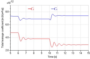
Fig. 7 shows influences of load variation on total leakage coefficients when keeping inputs of pump and valve constant (6 V, –15 mA, 5 mA). Set square wave signal to proportional relief valve and produce variable load pressure varying between 6 MPa and 9 MPa, which is approximate to a square wave, as shown in Fig. 7(a). Fig. 7(b) shows that total leakage coefficients of pump and motor in leaking control and replenishing control are similar to that in pump control, but are less fluctuant due to higher damping ratios. Fig. 7(c) indicates that and have the same variation tendency when the system is in leaking control, which causes wide variation of . However, Fig. 7(d) indicates that and have contrary tendency when the system is in replenishing control, which makes more constant with less variation.
Fig. 7Total leakage coefficients under variable loads
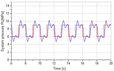
a) Load pressure
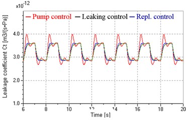
b) In pump control
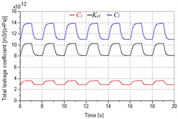
c) In leaking control
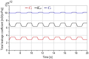
d) In replenishing control
In fact, we can find the answer from the expressions of , and , i.e. , , . Both and vary inversely with the , but is proportional to , in addition, and , so the system in replenishing control has comparatively stable total leakage coefficients.
The impacts of total leakage coefficient variation caused by load variation are as follows.
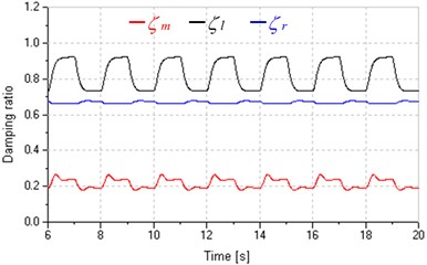
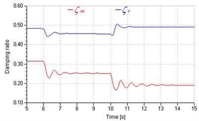
At the aspect of damping ratios, as shown in Fig. 8(a), for the same valve opening, damping ratios in replenishing control are small than that in leaking control, and more stable than that in leaking control and in pump control, which contributes to system control and prediction.
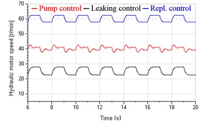
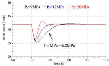
At the aspect of speed stiffness, as shown in Fig. 8(b), the speed amplitude in pump control, leaking control and replenishing control are 2 r/min, 5.3 r/min and 4.4 r/min, respectively, and hydraulic motor speed in leaking control and replenishing control is more approximate to a square wave signal compared with that in pump control, these imply that the systems in valve-pump parallel control own lower speed stiffness and are more sensitive to load variation due to the increase of total leakage coefficients, but the system in replenishing control has higher speed stiffness compared with that in leaking control. Fig. 9 presents that the replenishing control has more freedom to improve speed stiffness by raising the supply pressure of valve , just because raising will reduce the valve flow-pressure coefficient and total leakage coefficient according to and .
Fig. 8Damping ratios and hydraulic motor speed under variable loads
a) Damping ratios
b) Hydraulic motor speed
Fig. 9Hydraulic motor speed in replenishing control under different Ps
However, the system in leaking control doesn’t have such flexibility, because when SPDV is at the leaking status, both its flow gain and flow-pressure coefficient relate to load pressure not , but varies with load and can’t be intervened manually.
Although above regular laws are obtained as systems in open loop control, are still available to system in closed loop control.
According to above parameters analyses, the leaking control will be applied to improve low-speed performance of hydraulic motor at the start and stop stages, and the replenishing control will be applied to achieve rapid response to load variation at the uniform stage with high speed, these are examined in section 4.3 and 4.4 in detail, respectively.
4.3. Low-speed performance analysis
4.3.1. Theoretical basis
There are many influence factors on low-speed performance of hydraulic motors, such as internal factors (motor displacement ripple, leaking ripple and friction torque) and external factors (flow and pressure ripple of oil source, load disturbance), but the principal factor is friction torque. Friction is known as a complex nonlinear physical phenomenon, and could be described by static models or dynamic models [20-22]. Fig. 10 and Eq. (24) present a normal static model of friction torque, which takes into account stiction, Coulomb friction, viscous friction and Stribeck effect described by the third item of Eq. (24):
where is external torque, is static torque, is Coulomb friction torque, is relative speed, is viscous friction coefficient, is Stribeck speed, is sign function.
Fig. 10A normal friction model with Stribeck effect
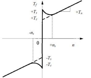
Stribeck effect is used to describe the friction behaviour at low speed [23]. As shown in Fig. 10, the friction torque is a function of speed , and decreases with increasing speed at the region of small speed (). This effect terribly affects the low-speed stability of hydraulic motors. Some previous studies [24-25] show that the necessary condition of keeping low-speed stability is:
where is system total leaking coefficient, is damping coefficient of friction torque and other parameters are defined as former. At the region of small speed, the slope between friction torque and speed is negative due to the Stribeck effect, i.e., 0.
The viscous damping coefficient is usually very small, so increasing system total leaking coefficient and inertia will improve the stability.
In the Fig. 10, is called critical speed. Hydraulic motor speed will oscillate below this speed, which is often called stick-slip phenomenon, and the oscillation will disappear above this speed could be given by [26-27]:
where is system stiffness, is system damping ratio. So increasing , and will obtain lower critical speed. could be given by [28]:
It is obvious that damping ratio is associated with total leaking coefficient and damping coefficient of friction torque . Increasing will increase and lead to lower critical speed. In addition, acts terrible nonlinear at small speed region. As shown in Fig. 10, the minus value of becomes larger and becomes smaller as speed decreases at the small speed region, which causes higher probability of oscillation and more difficulty of getting lower critical speed [29].
In addition, hydraulic pumps can’t works below its minimum stable speed or it will cause severe flow and pressure ripple; moreover, the electric motor can’t supply adequate torque to control the pump under comparatively low frequency, especially at start and stop.
Based on above analyses, the leaking control is employed to start and stop stages with low-speed. This method has following benefits.
1) The pump could work at a stable speed, which enables the flow of oil source more stable and electric motor could output adequate torque.
2) Increase total leaking coefficients and damping ratios by adding leakage controlled by the valve, which will enhance low speed stability and obtain smaller critical speed.
3) Hydraulic motor speed decreases with increasing the valve opening, and damping ratios variation resulting from the change of valve opening is just opposite to that of damping ratios at low-speed region discussed previously, and could compensate the reducing of damping ratios due to the friction negative slop, which contributes to smaller critical speed.
4.3.2. Verification
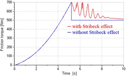
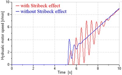
As discussion previous, hydraulic motors can’t work at low speed in variable speed hydraulic systems because pumps should works above its minimum stable speed. For highlighting advantage of the leaking control in improving low-speed performance, we even assume the pump could works at any low speed in following simulations. These simulations are carried out in open loop control for avoiding stability problem caused by the closed loop control. We adapt the friction model with Stribeck effect shown in Eq. (24), and make following setting: 700 Nm, 500 Nm, 0, 10 r/min.
Fig. 11 shows influences of Stribeck effect on friction torque and hydraulic motor speed when the system is in pump control. In the process, pump flow increases from zero to 7.2 L/min as the inverter input increases from zero to 2 V in 10 seconds. It is obvious that after adding Stribeck effect, the transition from static torque to Coulomb friction torque is an exponential not instantaneous and the low speed of hydraulic motor is unstable. All those prove that the friction model could well simulate actual friction existing in hydraulic motors in some degree. Fig. 11(b) also indicates that single pump control can't assure low-speed performance.
Fig. 11Influences of Stribeck effect on friction torque and motor speed in pump control
a) Friction torque
b) Hydraulic motor speed
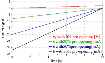
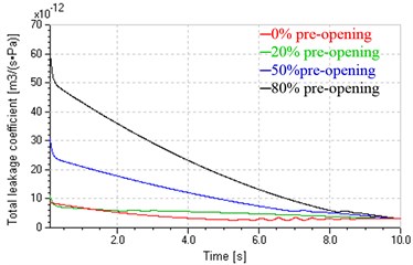
Fig. 12 shows influences of different pre-openings on start performance when the system is in leaking control. Fig. 12(a) shows control signals of the valve and inverter. Keeping the control signal of inverter constant (2 V corresponding to 600 r/min and 7.2 L/min), the control signal of the valve respectively decreases from –8 mA, –20 mA, –32 mA to zero, corresponding to pre-opening decreasing from 20 %, 50 %, 80 % to zero, respectively. The red curve (0 % pre-opening) is the control signal of inverter when the system is in pump control. Figs. 12(b) and (c) indicate total leakage coefficients and damping ratios in leaking control vary wildly with the valve inputs and reach maximum at the beginning of start. As shown in Fig. 12(d), compared with the pump control, the leaking control could basically overcome the influence of Stribeck effect and obtain sound low-speed stability, in addition, could control start time and acceleration by regulating the pre-opening, the ruler is that greater pre-opening produces greater lag and acceleration.
Fig. 12System response in leaking control
a) Control signals
b) Total leakage coefficients
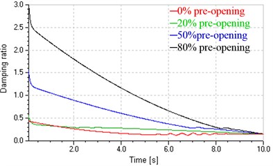
c) Damping ratios
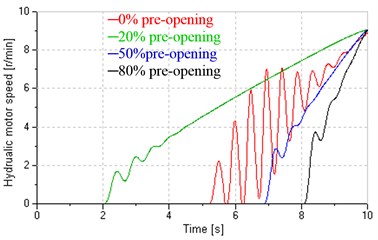
d) Hydraulic motor speed
Using leaking control at the stop stage will also obtain above similar property, here which is unnecessary to be verified in detail. Fig. 13 shows low-speed performance in closed loop control. It is clear that at the start and stop stages, single pump control can't obtain good low-speed performance because the instability in open loop control makes which in closed loop control worse. However, the leaking control could achieve good low-speed performance and good tracking in close loop control.
Fig. 13Low-speed performance in closed loop control
4.4. Rapid response performance analysis
According to the principle in section 2, the replenishing control is applied to improve response to load disturbance at the uniform stage with high speed. At this high speed stage, the Stribeck effect is ineffective and can be omitted. This section is carried out under closed loop control.
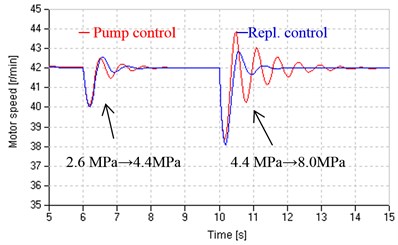
Fig. 14 shows dynamic responses in pump control and replenishing control to step loads, which are loaded by the proportional relief valve at 6 s and 10 s. These responses have following properties.
1) For any control manner, greater load causes larger speed drop and longer settling time.
2) For the same step load, the speed drop in replenishing control is larger than that in pump control, which illustrates that under closed loop control, the speed stiffness in replenishing control is still lower than that in pump control. That is because speed stiffness varies inversely with total leakage coefficients according to Eqs. (21)-(23), and there is , as shown in Fig. 14(b).
3) System parameters (total leaking coefficients and damping ratios) in replenishing control are comparatively stable, e.g. the damping ratio is round 0.5.
4) Replenishing control can achieve rapid response to load variation compared with pump control. There are two reasons: first, the systems in pump control and Replenishing control have the same natural frequency, i.e., , as discussion in Section 4.1; second, comparing Eqs. (4) and (7), there is , which means that valve SPDV responds faster than variable speed pump and could regulate flow more quickly.
Fig. 14Responses for step loads
a) Hydraulic motor speed
b) Total leakage coefficient
c) Damping ratio
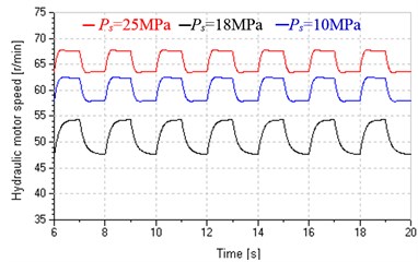
As shown in Fig. 15, the system in replenishing control could obtain two benefits by raising supply pressure .
1) Accelerating response. Referring flow gain and Eq. (20), increasing will increase and open loop gain and improve system response at last.
2) Improving closed stiffness. Referring flow-pressure coefficient , increasing will reduce and and increasing and reducing will enhance closed stiffness according to Eq. (23).
Fig. 15Hydraulic motor speed response for step loads under different Ps
4.5. Variable structure control
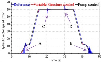
Based on the system principle in Section 2 and performance analyses in section 4.3 and 4.4, we apply variable structure control to the whole regulation process. As shown in Fig. 4, the system is loaded by the friction model with Stribeck effect and loading pump, set supply pressure of SPDV to 15 MPa, and step loads are respectively loaded at 20 s and 30 s and produces step load pressure of 3.8 MPa. The variable structure controller is also established and modes are switched according to the desired speed (, 60 r/min). When , the leaking control mode is put to use; when , the replenishing control mode is adopted; other else, the pump control mode is used. This section is carried out under closed loop control.
Fig. 16System response in a duty circle
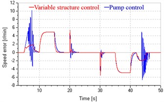
b) Speed error
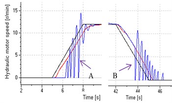
Start and stop stages (enlarged view)
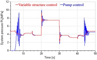
c) System pressure
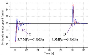
Uniform stage with high speed (enlarged view)
d) Damping ratios
The switch point at low speed (12 r/min) is determined by deviation of the flow produced by the variable speed pump working above its minimum stable speed (500 r/min) and leakages of pump and hydraulic motor. Therefore, set inverter input to 2 V, corresponding to pump initial speed of 600 r/min and flow of 7.3 L/min. The pre-opening of the valve should be set to permit the flow leaks entirely. Hence the initial current of the valve is –13 mA, corresponding to 32.5 % of opening. The switch point with high-speed should be slightly less than , and is set to 58 r/min.
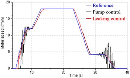
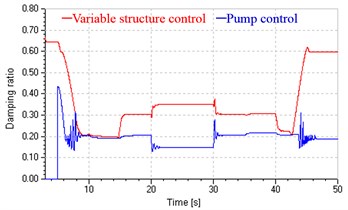
Compared with the system in single pump control, the system in variable structure control achieves good low-speed performance by leaking control at start and stop stages and rapid response to load variation by replenishing control at the uniform stage (shown in Fig. 16(a)), and gets smaller speed error in above three stages (shown in Fig. 16(b)), and could basically avoids pressure impact at start and stop (shown in Fig. 16(c)), and has more stable and greater damping ratios, which increase with decreasing speed at the start and stop stages and reach maximum value (shown in Fig. 16(d)).
Fig. 16(a) also shows the proposed system has a good speed tracking in the overall regulating process, and achieves smooth switch between different control modes, which can be explained from Fig. 17, which presents the valve and pump response in a duty circle. During the closed loop control process, both the variations of valve input and pump speed match previous supposition, and these inputs and corresponding flow are continuous without mutation.
Fig. 17Valve and pump responses in a duty circle
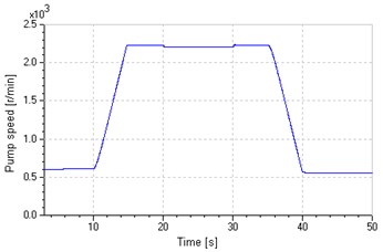
a) Pump speed
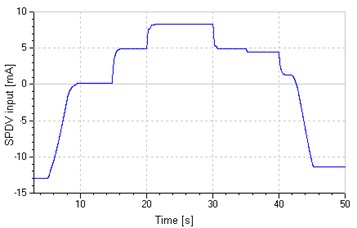
b) SPDV input
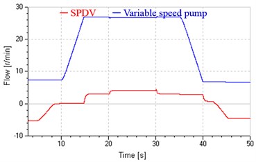
c) SPDV flow and pump flow
4.6. Efficiency analysis
Transmission of energy in hydraulic systems behaves as the flow of fluid with pressure, and the power is the product of flow and pressure. Pressure matches loads without human intervention. Hence the control of energy is essentially the control of flow. If the flow controlled by the pump and valve is assigned reasonably in the valve-pump parallel system, effective energy saving will be obtained. Here is defined as energy saving coefficient, where is output flow of the variable displacement pump and is flow passing through SPDV. Of course, the greater the value of is, the better the effect of energy saving will be. As shown in Fig. 17(c), majority of flow is supplied by the variable speed pump and only minority of flow is supplied by SPDV or leak through the valve in the whole process. So it is obvious that the variable structure control system possesses comparatively high efficiency while achieving good dynamic response. Moreover, the coefficient will become greater and the proposed system will be more efficient if the maximum speed rises. That is because the majority of flow corresponding to maximum speed is supplied by the pump not the valve, and the valve’s flow mainly varies with load variation.
5. Conclusions
This paper presents a new variable speed hydraulic system in valve-pump parallel variable structure control.
1) Compared with traditional pump control systems, valve-pump parallel control systems share the same natural frequency, but have greater total leaking coefficients and damping ratios, these vary widely with operating points (valve opening and load pressure).
2) At the start and stop stages, the leaking parallel valve control mode is employed to enhance low speed stability by increasing total leaking coefficients and damping ratios. Moreover, the increase of damping ratios caused by leakage controlled by the valve just compensates the reduction of damping ratios due to the friction negative slop, which further enhances low-speed performance.
3) At the uniform stage with high speed, the replenishing parallel valve control mode is employed to achieve fast response to load disturbance. Compared with the system in leaking control, that in replenishing control has more stable and suitable damping ratios and more flexibility, and could further improve dynamic response and speed stiffness by raising valve supply pressure.
4) In the whole process, control structures (modes) vary with control requirement and modes switch smoothly and a good speed tracking is obtained, moreover, the variable pump provides majority flow and the valve works at little flow status, so the proposed system still can work efficiently as pump control systems.
5) In all, the valve-pump parallel variable structure control establishes a flexible control mechanism by two channels of valve control and pump control, where control structures vary with control requirement, and could improve comprehensive performances of variable speed hydraulic systems with large power, such as low-speed performance, rapid response to load variation and high efficiency.
6. Prospect
In fact, we can improve system performances by two methods: control structure and control method, and this paper focus on the former. For emphasizing inherent superiorities of the proposed system, we just use simple internal corrections. For further improving dynamic characteristics of the proposed system, some advance control methods may be used, such as using friction compensation to improve low speed performance [30-31], and using adaptive robust control (ARC) to overcome the influence of timing variation and uncertainty of parameters [32-33].
References
-
Karunanidhi S., Singaperumal M. Mathematical modelling and experimental characterization of a high dynamic servo valve integrated with piezoelectric actuator. Proc. IMechE, Part I, J. Systems and Control Engineering, Vol. 224, Issue 4, 2010, p. 419-435.
-
Shi Z. R., Parke G., Granstrom J. Kinematic analysis of a swash-plate controlled variable displacement axial-piston pump with a conical barrel assembly. ASME Journal of Dynamic Systems, Measurement and Control, Vol. 132, Issue 1, 2010, p. 1-8.
-
Ding H. G., Zhao J. Y. Characteristic analysis of pump controlled motor speed servo in the hydraulic hoister. Int. J. Modelling, Identification and Control, Vol. 19, Issue 1, 2013, p. 64-74.
-
Kazuo N., Yutaka T. Energy saving type electrohydraulic servo system. Journal of Fluid Control, Vol. 18, Issue 3, 1988, p. 35-51.
-
Yutaka T., Tetsuji M., Kazuo N. Speed and displacement control of pump system for energy saving. Proc. of 2nd International Symposium on Fluid Power Transmission and Control, Shanghai, China, 1995, p. 12-16.
-
Yang H. Y., Yang J., Xu B. Computational simulation and experimental research on speed control of VVVF hydraulic elevator. Control Engineering Practice, Vol. 12, Issue 5, 2004, p. 563-568.
-
Manasek R. Simulation of an eletcro-hydraulic load-sensing system with AC motor and frequency changer. Proc. of 1st FPNI-PhD Symposium, Slovakia, 2000, p. 311-324.
-
Shen H. K., Jin B., Chen Y. Research on variable speed electro-hydraulic control system based on energy regulating strategy. Proc. of ASME International Mechanical Engineering Congress and Exposition, Chicago, USA, 2006, p. 230-236.
-
Shen H. K., Jin B., Chen Y. Variable speed hydraulic control system based on energy regulation strategy. Journal of Mechanical Engineering, Vol. 45, Issue 5, 2009, p. 210-213, (in Chinese).
-
Jin B., Shen H. K., Chen Y. Energy-regulation based variable speed hydraulic cylinder position control system. Journal of Mechanical Engineering, Vol. 44, Issue 1, 2008, p. 25-30.
-
Qi X. Y., Fu Y. L., Wang Z. L. Scheme analysis of power-by-wire airborne actuation system. Journal of Beijing University of Aeronautics and Astronautics, Vol. 25, Issue 4, 1999, p. 426-430, (in Chinese).
-
Cochoy O., Carl U., Thielecke B. F. Integration and control of electromechanical and electrohydraulic actuators in a hybrid primary flight control architecture. Proc. of International Conference on Recent Advances in Aerospace Actuation Systems and Components, 2007, p. 1-8.
-
Kang R. J., Jiao Z. X., Wang S. P. Design and simulation of electro-hydrostatic actuator with a built-in power regulator. Chinese Journal of Aeronautic, Vol. 22, Issue 6, 2009, p. 700-706, (in Chinese).
-
Ding H. G., Zhao J. Y., Li G. Z. Analysis of valve-pump combined high power hydraulic speed regulation schemes. Journal of China Coal Society, Vol. 38, Issue 9, 2013, p. 1703-1709, (in Chinese).
-
Ding H. G., Zhao J. Y., Zhao L. Analysis on electrohydraulic speed servo control schemes for anti-explosion hydraulic hoisters. Journal of China Coal Society, Vol. 36, Issue 8, 2011, p. 1407-1411, (in Chinese).
-
Manring N. D. Hydraulic control systems. New York, John Wiley & Sons, 2005.
-
Alessandro R., Salvatore M., Nicola N. Modelling a variable displacement axial piston pump in a multibody simulation environment. ASME J. Dynamic Systems, Measment and Control, Vol. 129, Issue 4, 2007, p. 456-468.
-
Karnopp D. Computer simulation of stick-slip friction in mechanical dynamic systems. Journal of Dynamic Systems, Measurement and Control, Vol. 107, 1985, p. 100-103.
-
Liu L. L., Liu H. Z., Wu Z. Y., et al. An overview of friction models in mechanical systems. Advances in Mechanics, Vol. 38, Issue 2, 2008, p. 201-213.
-
Armstrong B., Dupont P., Canudas de Wit C. A survey of models, analysis tools and compensation methods for the control of machines with friction. Automatica, Vol. 30, Issue 7, 1994, p. 1038-1183.
-
Cheok K. C., Hu H., Loh N. K. Modeling and identification of a class of servomechanism system with stick-slip friction. Transactions of the ASME Journal of Dynamic Systems, Measurement, and Control, Vol. 110, Issue 3, 1988, p. 324-328.
-
Ding Q., Zhai H. M. The advance in researches of friction dynamics in mechanics system. Advances in Mechanics, Vol. 1, 2013, p. 112-131.
-
Bo L. C., Pavelescu D. The friction-speed relation and its influence on the critical velocity of stick-slip motion. Wear, Vol. 82, Issue 3, 1982, p. 277-289.
-
Yanada H., Hibi A., Ichikawa T. Investigation of the low speed stability of oil hydraulic motors (3rd report, the case of pump-controlled axial piston motors). Transactions of the Japan Society of Mechanical Engineers, Part B, Vol. 52, Issue 476, 1986, p. 1657-1664.
-
Wang X. Y., Fu Y. L., Wang X. Y. Analysis on the low speed performance of electrohydraulic servo motors in hydraulic simulator with three shafts. Journal of Astronautics, Vol. 17, Issue 2, 1996, p. 85-90, (in Chinese).
-
Jiang Y. X. A study on the problem of low speed jump of servosystems. Acta Automatica Sinica, Vol. 8, Issue 2, 1982, p. 136-144, (in Chinese).
-
Zeng Q. S., Qin J. C. Analysis on the low speed function of turntable servo system. Journal of Chinese Inertial Technology, Vol. 9, Issue 2, 2001, p. 64-69, (in Chinese).
-
Wang X. Y., Liu Q. H. Investigation of mechanism of low speed in electrohydraulic position servomotor system. Journal of Harbin Institute of Technology, Vol. 25, Issue 2, 1993, p. 60-68, (in Chinese).
-
Wang M. Z., Xie W. M. An investigation into low speed stability of piston motors. J. Gansu Univ. Technol., Vol. 15, Issue 2, 1989, p. 1-7, (in Chinese).
-
Zeng H., Sepehri N. Tracking control of hydraulic actuators using a LuGre friction model compensation. Asme J. Dynamic Systems, Measment and Control, Vol. 130, Issue 1, 2008, p. 145021-145027.
-
Tomei P. Robust adaptive friction compensation for tracking control of robot manipulators. IEEE Trans. Auto Contr., Vol. 45, Issue 6, 2000, p. 2164-2169.
-
Yao B., Tomizuka M. Adaptive robust control of MIMO nonlinear systems in semi-strict feedback forms. Automatica, Vol. 37, 2001, p. 1305-1321.
-
Yao B. Integrated direct/indirect adaptive robust control of SISO nonlinear systems in semi-strict feedback form. Proceedings of the American Control Conference, Denver, Colorado, June, 2003, p. 3020-3025.
About this article

This work is supported in part by the National Nature Science Foundation of China (51175497), the Qing Lan Project of Jiangsu, China and the Innovation Foundation for Graduate Students of Jiangsu, China (CX10B_135Z). We also give our great thanks to Zhu Quan Min, University of the West of England, UK, for his valuable suggestions.
