Abstract
The purpose of this paper is to present a 2-D equivalent finite element model of a quadratic linear electromagnetic actuator that can save space and power as it does not employ an energy conversion system. A 2-D model, while being fairly accurate, is preferable to a 3-D finite element analysis for the design and analysis of a quadratic linear electromagnetic actuator as it requires significantly lower computing resources and results in faster calculations. We calculate the effective coil length for the equivalent 2-D finite element model and validate the accuracy of this model with experimental data.
1. Introduction
Voice coil actuator are demanding applications as precision actuators widely in IT, automobile, defense and medical systems and so on. It has numerous designs as the application. The flat coil actuaor has being used in IT systems as computer hard disk, camera module, semiconductor equipment and etc. [1-3] and the cylindrical actuator has being used in automobile as electromagnetic engine valve, vibration absorber and etc. [4, 5] Especially, the quadratic linear electromagnetic actuators leads to higher magnetic force due to large number of permanent magnets compared to other voice coil motors [6]. A 3-D Finite element (FE) model is a rather effective approach to model quadratic liear electromagnetic actuators [7-9], but a 3-D simulations utilize significant computer resourses and typically, 3-D dynamic simulations cannot be performed on personal computers. Therefore, it is often convinient to employ simpler 2-D equivalent model to simulate static and dynamic behavior of linear electromagnetic actuators; simulations that can be preformed using personal computers [10]. In this paper, we present and validate an equivalent 2-D FE model that replaces the 3-D FE model. To determine the depth of equivalent 2-D model, the effective coil length is calculated. The prototype of the quadratic electromagnetic actuator is manufactured, and the accuracy of the proposed equivalent 2-D FE model is verified experimentally.
2. Structure and operation principle of electromagnetic linear actuator
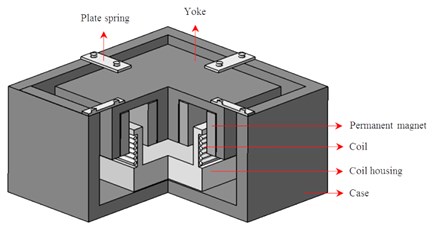
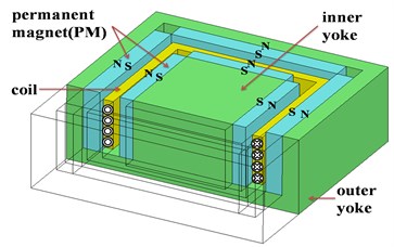
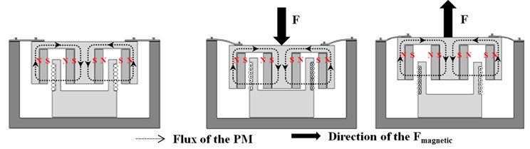
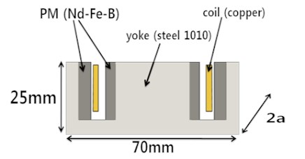
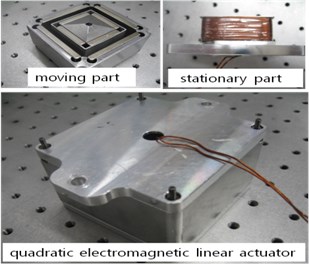
Figs. 1(a) and 1(b) show a schematic diagram and a cross-section of the quadratic linear electromagnetic actuator respctively. The moving part consists of an inner steel yoke with four small magnets and an outer steel yoke with four larger magnets [11-13]. The inner and outer magnets create a very dense magnetic field that a strong magnetic force. The stationary part consists of the electromagnetic coil and housing. Fig. 1(c) shows the operation principle of the quadratic linear electromagnetic actuator. The moving part is guided by mechanical plate springs and moves up and down by the stored spring energy and the magnetic Lorentz force as the electromagnetic coil remains fixed [14, 15].
Fig. 1Quadratic electromagnetic linear actuator: a) schematic diagram, b) cross section of magnetic actuator, c) operating principle
a)
b)
c)
3. Equivalent 2D FE Model
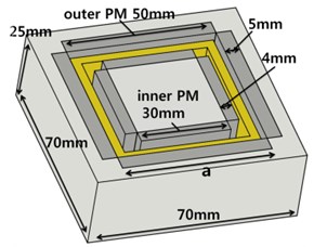
Fig. 2(a) is the 3-D FE model of the quadratic linear electromagnetic actuator. Each of the four sides of the square- shape coil interacts with the magnetic field of the outer and inner magnets. We assume that the magnetic force of the four sides of the coil in 3-D model is twice the magnetic force of FE model. Therefore, we set the depth of the equivalent 2-D model to be twice the length of the inner magnet and outer magnet or the mean length of the inner and outer magnets. The length of the permanent inner magnet is 30 mm, that of the permanent outer magnet is 50 mm and the average length is 40 mm. Therefore, the corresponding depths of the equivalent model are 60 mm, 100 mm, and 80 mm, respectively. We have created a 2-D static FE equivalent model and a 3-D static FE full model utilizing the commercial “MAXWELL” FEA software. The resulting magnetic force calculated by these two models are then compared. The nonlinear B-H characteristic of steel 1010 is applied to the steel yoke and the magnetic properties of the permanent magnet are shown in Table 1. The modeling results are presented in Table 2.
Fig. 2Simulation model: a) 3-D model, b) equivalent 2-D model
a)
b)
Table 1Specification of the Neodymium permanent magnet
Neodymium permanent magnet | ||
Symbol | Parameter | Value |
Residual induction | 1.23 T | |
Coercive | –890 kA/m | |
Relative permeability | 1.1 | |
Table 2Result of the FE analysis with 2-D and 3-D FE models
Case | 3D model | 2D equivalent model | |
Magnetic force (N) | Magnetic force (N) | Ratio | |
Inner PM (60 mm) | 11.7 | 9.6 | 0.82 |
Average (80 mm) | 12 | 1.1 | |
Outer PM (100 mm) | 16 | 1.367 | |
The ratios of magnetic forces calculated for the 2-D equivalent models to that of the full 3-D model are 0.82 if the depth is of the system is assumbed to be double the length of the inner PM and that ratio is 1.367, if the depth of the system is double the legth of the outer PM. In the case when the depth of the modelled system is assumed to be twice the average length of PM, the ratio is 1.1. There is at least 10 % error using this method. Accordingly, we need to find a new way to calculate the depth of the equivalent 2-D model. The depth of the equivalent 2-D FE model to replace the 3-D model is proposed. The Lorentz force to drive the actuator is expressed by a cross vector between the flux density and coil length in the Eq. (1) [16]:
where is the number of coil turns, is the residual flux density of the PM in the air gap, is the input current and l is the effective length of coil in the air gap.
Fig. 3Direction of flux at part1 and part2
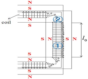
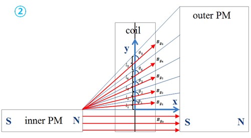
Fig. 4The direction of the flux in five divided edge parts
The 2-D FE model considers the geometry of the coils presented in Fig. 3 where the magnetic field is perpendicular to the long axis of coil wire, a situation where Lorentz force is maximized. We subdivide each side of the coil into part 1 where the magnetic field is perpendicular to the direction of coil length and part 2 where it is not.
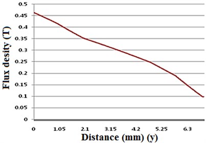
Accordingly, the total coil length of part 1, which is equal to the length of the inner magnet, is fully converted to the depth of the 2-D model while the coil length of part 2 cannot be accurately converted to the depth of the 2-D model. In order to arrive at the accurate conversion of the coil length of part 2, it first needs to be modified to the effective coil length, which can be considered to be perpendicular to the magnetic field and then it will be directly converted to the depth of 2-D model. In order to calculate the effective coil length of part 2, we divide the coil at part 2 into five segments. Fig. 4 shows the direction of the magnetic field in the five segments of the coil. through are defined as the length of each coil and is defined as the angle of the magnetic field at each segment with respect to the direction of the long axis of the wire of the coil. Using finite element analysis, the magnetic flux distribution at part 2 was evaluated. Fig. 5 demonstrates the calculated flux density in the airgap in the edge parts. The magnitude of flux density from to varies. We will use the weight () defined as the ratio of to , to calculate the effective coil length, from which result we will deduce the depth of the 2-D model. The weight () is:
Fig. 5The flux density at the airgap of edge parts 2 (Fig. 4)
4. Verification of equivalent 2-D model by experiment
In this section, we validate the 2-D equivalent model. In section 4.1, FE dynamic simulation is performed based on the 2-D equivalent model. In section 4.2, the simulation results are validated against the empirical data collected using the fabricated quadratic linear electromagnetic actuator.
4.1. 2-D Dynamic finite element analysis
The dynamic FE analysis calculated the coupled system composed of magnetic, electric and mechanical subsystems. Table 4 and Table 5 summarize the data for the electric and mechanical subsystems, respectively. The current through the coils was of a sine waveform described by Eq. (5) below and the resultant magnetic force oscillated as a sine waveform [17]:
Table 4Specification of the electric subsystem
Electric subsystem | ||
Symbol | Parameter | Value |
Input current | 3 A | |
Input current frequency | 50 Hz | |
Turns | Number of coil turns | turns |
Table 5Specification of the mechanical subsystem
Mechanical subsystem | ||
Symbol | Parameter | Value |
Yoke and PM mass | 2.15 kg | |
Spring coefficient | 110 kN/m | |
Natural frequency | 22 Hz | |
Eq. (6) below describes the motion of the mechanical subsystem:
where is a total mass of the moving part, is the damping coefficient, is the spring coefficient and is the natural frequency of the actuator. In this FEA, the damping force is neglected.
The initial conditions are: , .
To solve the coupled system, the dynamic FEA is performed with a time step of 0.1 millisecond for a time period of 0.1 seconds.
Fig. 6Plot of the magnetic force at the input frequency of 50 Hz
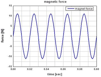
Fig. 7Plot of the spring force at the input frequency of 50 Hz
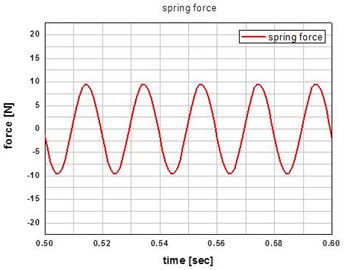
Fig. 8Plot of the excitation force at the input frequency of 50 Hz
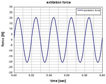
Figs. 6 and 7 show the resultant magnetic force and spring force, respectively. The total excitation force of the actuator is calculated by subtracting the spring force from the magnet force. Excitation force is shown in Fig. 8.
Fig. 9Prototype of the quadratic linear actuator
4.2. Experiment
In order to verify the result of dynamic 2-D finite element analysis, a prototype of the quadratic linear actuator (see Fig. 9) was manufactured.
Fig. 10 demonstrates the experiment setup consisting of power supply, load cell, NI-board and a personal computer [18]. With the power supply, a sinusoidal wave of 3 A 50 Hz is applied to the coil and the force of moving part versus time is measured by the load cell every 0.1 millisecond [19, 20].
Fig. 10a) Schematic diagram of experimental set up, b) Experimental set up
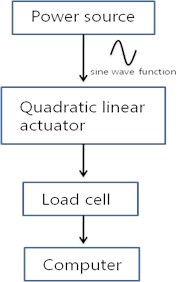
a)
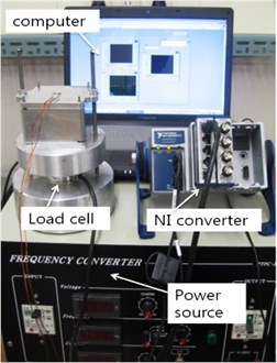
b)
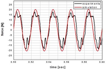
Fig. 11 shows the measured excitation force and the simulated excitation force with the equivalent 2-D FE model. The graph of experiment is not smooth due to the error of experiment, but the difference between the model results and the experimental data is less than 5.6 % which shows the validity of 2-D FE model.
Fig. 11Plot of experimental vs. simulated force
5. Conclusion
In this work, we propose an equivalent 2-D FE model of the quadratic actuator to replace the 3-D FE model. The accuracy of the equivalent 2-D FE model was verified with experimental data and the deviation of the experimental results from the 2-D FEA model was below 5.6 %. The equivalent 2-D FE model can be used to design and analyze the performance of quadratic linear electromagnetic actuators by employing low computational power resources such as personal.
References
-
Nakazato Hiroshi Rotary voice coil motor with a flat coil. U.S. Patent No. 5, 122, 702, 1992.
-
Oveyssi Kamran, Alireza Rahimi Dual coil voice coil motor. U.S. Patent No. 5, 621, 591, 1997.
-
Yeom D. H., Park N. J., Jung S. Y. Digital controller of novel voice coil motor actuator for optical image stabilizer. International Conference on Control, Automation and Systems, 2007.
-
Boldea Ion, Syed A. Nasar Linear electric actuators and generators. Electric Machines and Drives Conference Record, 1997.
-
Chen Yi-De, Chyun-Chau Fuh, Pi-Cheng Tung Application of voice coil motors in active dynamic vibration absorbers. Magnetics, Vol. 41, Issue 3, 2005, p. 1149-1154.
-
Stratton Julius Adams Electromagnetic Theory. John Wiley & Sons, Vol. 33, 2007.
-
Kuk J. Y., Lim J. H. A study on vibration characteristic of engine mount system of a medium duty truck at the key on/off. Trans. of KASE, Vol. 16, Issue 4, 2008, p. 97-102.
-
Choi J. Y., Lee W. H., Shon H. C., Kim S. S., Kim J. H. A study on decoupler of active engine mount for vehicle vibration reduction. Conference KASE, 2009, p. 1142-1426.
-
Citipitioglu A. M., Haj-Ali R. M., White D. W. Refined 3D finite element modeling of partially-restrained connections including slip. Journal of Constructional Steel Research, Vol. 58, Issue 5, 2002, p. 995-1013.
-
Bastos João Pedro A., Nelson Sadowski Electromagnetic Modeling by Finite Element Methods. CRC press, 2003.
-
Liang Tian-Ye, Shi Wen-Ku Study on electromagnetic actuator active engine mount with fuzzy control. International Conference on Mecahtronics and Automation, 2009, p. 3010-3014.
-
Sumali Hartono, Harley Cudney An active engine mount with a piezoelectric stacked actuator. Proceedings of the 35th SDM Conference, 1994.
-
Bohn C., et al. Active control of engine-induced vibrations in automotive vehicles using disturbance observer gain scheduling. Control Engineering Practice, Vol. 12, Issue 8, 2004, p. 1029-1039.
-
Sohn J. W., Paeng Y. S., Choi S. B. An active mount using an electromagnetic actuator for vibration control: experimental investigation. Proceedings of the Institution of Mechanical Engineers Part C, Journal of Mechanical Engineering Science, Vol. 224, 2009, p. 1-9.
-
Chai Hi-Dong Electromechanical Motion Devices. Prentice Hall, 1998.
-
Hwang K. I., Kim J. H. Single-axis flat electro-magnetic actuator using shorted turn for fast initial response. Journal of Korean Medical Science, Vol. 19, Issue 6, 2009, p. 222-226.
-
Yoon S. M., Kim J. H., Kim J. H. Mathematical modeling and analysis of vibration characteristics of smart-phone. International Journal of Precision Engineering and Manufacturing, Seoul, South Korea, p. 135-010.
-
Gene F. Franklin, Powell J. David, Abbas Emami-Naeini Feedback Control of Dynamic System. 4th ed., Prentice Hall, 2004, p. 368-500.
-
Fuller C. R., Elliott S. J., Nelson P. A. Active Control of Vibration. Academic Press Limited, London, 1996.
-
Rao S. S. Mechanical vibration. Pearson Education International, p. 409-422, 2004.
About this article

This research was supported by Yeungnam University research grant in 2014.
