Abstract
A nonlinear vibration isolator with High-Static-Low-Dynamic-Stiffness (HSLDS) characteristic comprised of vertical spring and horizontal spring is presented in this paper. Response of the nonlinear vibration isolator under three different kinds of base shock excitations is considered, the dynamic motion can be approximately described by the classic Duffing equation. A transformation function and ultra-spherical polynomial approximation method are employed to determine the shock response and compared with numerical method. Then performance of the nonlinear vibration isolator under shock excitations is evaluated by three performance indicies (Maximum Absolute Displacement Ratio (MADR), Maximum Relative Displacement Ratio (MRDR) and Maximum Acceleration Ratio (MAR)), and also compared with a linear one. Results show that the analytic method suits for weak nonlinearity and the performance of the nonlinear vibration isolator under shock excitations is greatly influenced by the input shock magnitude and structural parameters.
1. Introduction
Passive vibration isolators are widely used to attenuate unwanted vibrations in the engineering industry [1, 2]. A simple linear spring-damper passive vibration isolator can provide an effective isolation when the excitation frequencies are greater than times the natural frequency of the isolation system. As is well known, in order to achieve a better isolation performance, one can reduce the spring stiffness or increase the mass. But these two strategies are undesirable in practical engineering. Reduce spring stiffness can cause a larger static displacement on the application of a static load, increase the mass is limited by practical conditions. In order to overcome this limitation, nonlinear vibration isolator with High-Static-Low-Dynamic-Stiffness (HSLDS) can be used. HSLDS means the nonlinear vibration isolator have a high static stiffness with a small static displacement to withstand a static load, and a small dynamic stiffness to achieve a low natural frequency [3].
Nonlinear vibration isolators that have HSLDS property have been studied by many authors. Ibrahim [4] summarized many different kinds of nonlinear vibration isolators in detail. Carrella and Kovacic et al. [5-8] proposed a nonlinear vibration isolator using a vertical spring in parallel with two oblique springs to get the HSLDS property, and studied force and displacement transmissibility of this nonlinear vibration isolator. Zhou and Liu [9] used a mechanical spring and magnetic spring to build a tunable HSLDS vibration isolator. Le and Ahn [10] considered a vibration isolation system in low frequency excitation region with HSLDS property for vehicle seat isolation. Liu et al. [11] used a vertical spring in parallel with Euler buckled beam to build this nonlinear vibration isolator. A. D. Shaw et al. [12] proposed a HSLDS vibration isolator using nonlinear spring mechanism incorporated with a bistable composite plate.
In these previous researches, they studied response and transmissibility of this HSLDS vibration isolator under sinusoidal excitation for both force and displacement excitations, few studies have drawn attention to the random excitation [13,14] and shock excitation [15,16], which are common forms of excitations in practice. Shock excitation is considered in this paper. Linear shock isolation problems are studied fully by many authors [1, 15]. Snowdon [16] presented the response of nonlinear shock isolator and concluded that a soft spring performs better than a hard spring. Balandin [17] reviewed optimal shock and vibration isolation including mathematical foundations of both optimal open-loop and optimal feedback isolation systems. N. Chandra Shekhar et al. [18] considered the response of nonlinear dissipative shock isolators with non-linear spring and non-linear damper, and showed that the non-linearity in the stiffness has less effect on the response of the isolator than the non-linearity in the damping. They [19] also considered the performance of four different types of non-linear isolators and absorbers to shock excitations, and concluded that the three-element and two-stage isolators are preferable in the presence of non-linear cubic damping. Liu et al. [20] investigated the performance of a zero stiffness isolator under shock excitations using numerical methods, but failed to consider using analytic methods to indicate the shock response.
Various analytic methods have been studied for transient analysis of nonlinear systems. In this paper, a transformation function with ultra-spherical polynomial approximation method [21, 22] are used. In Section 2, a nonlinear passive vibration isolator with HSLDS characteristic comprised of vertical spring and horizontal spring is presented and three different kinds of base shock excitations are considered. In Section 3, analytic results obtained by using ultra-spherical polynomial method are compared with numerical results. In Section 4, three performance indices are considered to evaluate the performance of the nonlinear isolator and compared with a linear one. Conclusions are drawn in Section 5.
2. Modeling of nonlinear vibration isolator with HSLDS characteristic
A nonlinear vibration isolator with HSLDS characteristic comprised of vertical spring and horizontal spring is shown in Fig. 1. This model has been studied in detail in [5, 8], so only brief description is presented in this section.
Fig. 1Model of a nonlinear vibration isolator with HSLDS characteristic
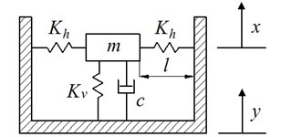
The force-displacement characteristic of the system is given as:
where is the stiffness of the vertical spring, is the stiffness of the horizontal spring. is the initial length of the horizontal springs, is the length when they are in the horizontal position and is the displacement from the static equilibrium position.
When the amplitude of the displacement is limited to about 40 % of the static displacement, the approximation of Eq. (1) is given by:
Eq. (2) can be written in non-dimensional form as:
where is the static displacement of the system after being loaded with mass.
It can be seen from Eq. (3) that if 1, the horizontal springs reduce the linear stiffness of the isolator such that the stiffness is less than the stiffness of the vertical spring alone. If 1, then must be greater than or equal to 2/3 so that the stiffness of the isolator can keep positive and have a snap-through characteristic [6, 8].
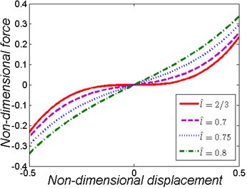
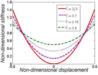
The non-dimensional force-displacement curves and stiffness-displacement curves of the nonlinear vibration isolator for various values of when 1 are shown in Fig. 2. It can be clearly seen that when 1, decrease can reduce the linear stiffness which is less than the stiffness of the vertical spring alone, but with the penalty for an increase in the nonlinearity and the stiffness region where the dynamic stiffness smaller than the linear one reduces. Overall, the nonlinear vibration isolator with HSLDS characteristic can expand the isolation frequency range without losing the support capacity, which is superior to the linear isolator.
Fig. 2Non-dimensional force-displacement and stiffness-displacement curves of the nonlinear vibration isolator for various values of l^ when k^=1
a)
b)
When the base of the system is subjected to shock excitations, the dynamic motion equation of the system is given as:
where and are the absolute displacements of the mass and base respectively, and the dots denote derivatives with respect to time . The initial conditions on are taken as . Eq. (4) can be written in non-dimensional form as:
where , , , , , , . The primes denote derivatives with respect to is the maximum magnitude of the shock input.
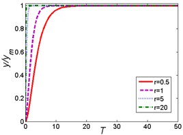
Three common kinds of base shock excitations [18, 19, 23] are considered: rounded displacement step, rounded displacement pulse and oscillatory displacement step. The three common base shock excitations are used to represent a discrete irregularity on the road, such as a bump or a vertical mismatch between sections of the pavement. The three shock excitations are shown in Fig. 3 and the mathematical expressions are given as:
The non-dimensional function can be obtained as follows:
where is the severity parameter. Greater means a more severe shock signal.
Fig. 3Three common kinds of base shock excitations: a) rounded displacement step; b) rounded displacement pulse; c) oscillatory displacement step
a)
b)
c)
3. Response of the nonlinear vibration isolator under shock excitations
Eq. (5) can be expressed in a general form:
where denotes the nonlinear function. The initial conditions of Eq. (12) are taken as . The solution of Eq. (12) can be solved by using the transformation:
Substitution of Eq. (13) in Eq. (12) yields:
Choosing function satisfies the condition:
Substituting Eq. (15) into Eq. (14) gives:
where Eq. (16) subjected to the initial conditions , .
Ultra-spherical polynomial approximation method [21, 22] can be applied to Eq. (16). The solution of Eq. (16) is assumed as:
where , .
Then gives:
which subjected to the initial conditions:
where , . The right-hand side of Eq. (18) and Eq. (19) are periodic functions of with period . The left-hand side of Eq. (18) and Eq. (19) are proportional to the small parameter , so they are slowly varying functions of time. So the right-hand sides are expanded in ultra-spherical polynomials in range , the expansions are only restricted to the first term, which gives:
where is the ultra-spherical polynomial index. Combining Eq. (20)-(23) and Eq. (15) can determine the function , . Then the response of the system can be obtained.
The nonlinear function in Eq. (5) equals , using the transformation gives:
Expanding the right-hand sides of Eq. (24) and Eq. (25) in ultra-spherical polynomials and retaining the first term yields:
where , is the gamma function, is the Bessel function of the first kind of order .
The solution of Eq. (26) can be easily obtained:
Response of the nonlinear vibration isolator under rounded displacement step shock excitation is first considered. Combing Eq. (6) and Eq. (15) gives:
Then can be obtained:
where , .
Combing Eq. (15), Eq. (27) and Eq. (30) yields:
where . Integrating Eq. (31) and applying the initial conditions lead to:
where is defined in the Appendix.
Using Eq. (13), Eq. (28), Eq. (30) and Eq. (32), the response of the nonlinear vibration isolator under rounded displacement step shock excitation can be obtained.
Response of the nonlinear vibration isolator under rounded displacement pulse shock excitation is then considered. Combing Eq. (7) and Eq. (15) gives:
Then can be obtained:
where:
Combing Eq. (15), Eq. (27) and Eq. (34) yields:
Integrating Eq. (35) and applying the initial conditions lead to:
where is defined in the Appendix.
Using Eq. (13), Eq. (28), Eq. (34) and Eq. (36), the response of the nonlinear vibration isolator under rounded displacement pulse shock excitation can be obtained.
Finally, response of the nonlinear vibration isolator under oscillatory displacement step shock excitation is considered. Combing Eq. (8) and Eq. (15) gives:
Then can be obtained:
where:
Combing Eq. (15), Eq. (27) and Eq. (38) yields:
Integrating Eq. (39) and applying the initial conditions lead to:
where is defined in the Appendix.
Using Eq. (13), Eq. (28), Eq. (38) and Eq. (40), the response of the nonlinear vibration isolator under oscillatory displacement step can be obtained.
The ultra-spherical polynomial index is used. Choosing the parameter , , , and different are used when conducting the following investigation.
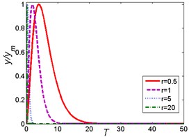
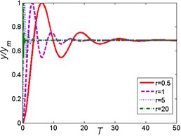
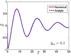
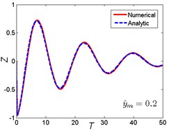
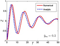
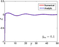
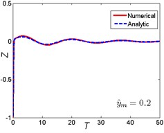
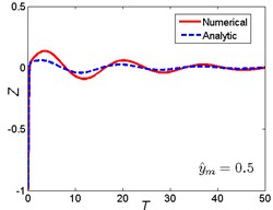
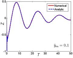
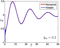
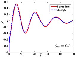
Approximate results using ultra-spherical polynomial method are compared with numerical results. The numerical results can be obtained by solving Eq. (5) using the classical fourth order Runge-Kutta method. The comparison is shown in Fig. 4. It can be seen that when the magnitude ratio is a smaller one (), which indicates that the nonlinear parameter is small, the ultra-spherical polynomial approximation method gives very well results compared with the numerical results for the three base shock excitations cases. When the magnitude ratio increases to a lager one (0.5), which indicates that the nonlinear parameter becomes larger, the analytic results depart from the numerical results, the error becomes larger for the three base shock excitations cases. But compared to the rounded displacement step and rounded displacement pulse cases, the error between analytic results and numerical results for the oscillatory displacement step is smaller than these two cases. So from these comparisons, it can be seen that the ultra-spherical polynomial approximation method suits for the smaller nonlinear parameter and weak nonlinearity.
Fig. 4Comparison between analytic and numerical results: a) rounded displacement step; b) rounded displacement pulse; c) oscillatory displacement step
a1)
a2)
a3)
b1)
b2)
b3)
c1)
c2)
c3)
4. Performance of the nonlinear vibration isolator under shock excitations
As is shown in Eq. (5), the responses of the nonlinear vibration isolator under different base shock excitations are determined by the stiffness ratio , the length ratio , the magnitude ratio and the severity parameter . When the stiffness ratio is fixed, the response are determined by the other parameters.
In this section, considering two cases: (1) 1, is taken as the value , , , investigate the performances of the nonlinear vibration isolator under varied severity parameter with same and different magnitude ratio , the value of is varied with , , . The effect of the magnitude ratio on the performances of the nonlinear vibration isolator is studied and compared with a linear one. (2) 1, is taken as the value , , , investigate the performances of the nonlinear vibration isolator under varied severity parameter with same and different length ratio , the value of is varied with , , . The effect of the length ratio on the performances of the nonlinear vibration isolator is studied and compared with a linear one. For all of the cases considered, the damping ratio coefficient is taken as .
The performances of the nonlinear and linear vibration isolator are evaluated by three performance indices [19, 20], which defined as follows:
Maximum absolute displacement ratio ;
Maximum relative displacement ratio ;
Maximum acceleration ratio .
The Maximum acceleration ratio (MAR) is expressed in dB scale as .
As is shown in the previous part, the ultra-spherical polynomial approximation method suits for weak nonlinearity and small nonlinear parameter, so the numerical method using Runge-Kutta method is used in this section.
4.1. Maximum absolute displacement ratio (MADR)
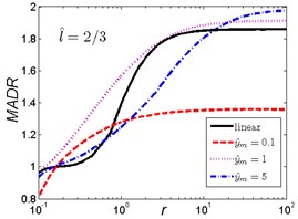
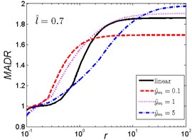
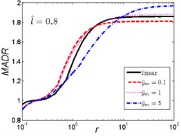
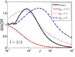
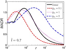
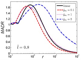
The MADR curves of the nonlinear vibration isolator under rounded displacement step shock excitation of the two cases are shown in Fig. 5 and Fig. 6. The MADR curve of the linear one is also plotted in the same figure for comparison.
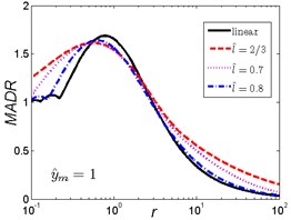
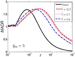
Fig. 5MADR curves of HSLDS vibration isolator under rounded displacement step excitation varied with shock parameter r when l^ takes a fixed value and y^m varies
a)
b)
c)
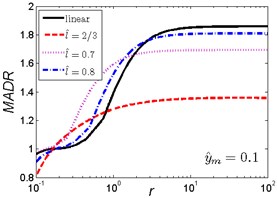
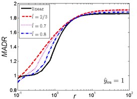
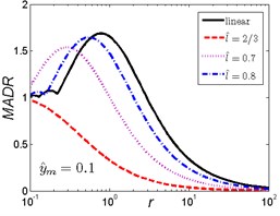
Fig. 6MADR curves of HSLDS vibration isolator under rounded displacement step excitation varied with shock parameter r when y^m takes a fixed value and l^ varies
a)
b)

c)
As can be seen in Fig. 5, when the length ratio is fixed, the effect of the magnitude ratio on the performances of the nonlinear vibration isolator under rounded displacement step is almost the same in the three cases. When the severity parameter is a small one (), the MADR of the nonlinear vibration isolator is lower than the linear one; but when increases to a certain range, different and corresponds to the different range (e.g. 0.1, 0.2 ), the MADR of the nonlinear vibration isolator is higher than the linear one; when continues to increase, the nonlinear vibration isolator can have a lower MADR over the linear one; if reaches to a higher value, the MADR of the nonlinear vibration isolator maintains a constant value, the MADR becomes larger with the increase of magnitude ratio , when is a smaller one, the MADR is lower than the linear one and falling the most, this is because smaller provides a larger lower dynamic stiffness region and the overall actual damping ratio is larger.
As is shown in Fig. 6, when the magnitude ratio is fixed, the effect of the length ratio on the performances of the nonlinear vibration isolator is not the same in each case. When is a small one, the MADR of the nonlinear vibration isolator can reach a lower value than the linear isolator after approaches to a value, the MADR becomes larger with the increase of the length ratio ; When , the MADR of the nonlinear vibration isolator is always higher than the linear one; When is a larger one , the MADR of the nonlinear isolator is higher than the linear one except increases to a certain range (about ), and the MADR becomes larger with the increase of the length ratio .
The MADR curves of the nonlinear vibration isolator under rounded displacement pulse shock excitation of the two cases are shown in Fig. 7 and Fig. 8. The MADR curve of the linear one is also plotted in the same figure for comparison.
Fig. 7MADR curves of HSLDS vibration isolator under rounded displacement pulse excitation varied with shock parameter r when l^ takes a fixed value and y^m varies
a)
b)
c)
Fig. 8MADR curves of HSLDS vibration isolator under rounded displacement pulse excitation varied with shock parameter r when y^m takes a fixed value and l^ varies
a)
b)
c)
As can be seen in Fig. 7, when the length ratio is fixed, the effect of the magnitude ratio on the performances of the nonlinear vibration isolator under rounded displacement pulse is almost the same in three cases, but is different from the rounded displacement step shock excitation. For and small magnitude ratio , the MADR of the nonlinear vibration isolator is always lower than the linear one. Except this special case, the MADR of the nonlinear vibration isolator first increases, reaches a peak value and then decreases with the increase of . For small parameter , the MADR of the nonlinear vibration isolator is larger than the linear one; when increases to a certain range, different and corresponds to the different range (e.g. 2/3, 1, ), the MADR of the nonlinear vibration isolator is lower than the linear one; when continues to increase, the nonlinear vibration isolator can have a higher MADR over the linear one, the MADR becomes larger with the increase of magnitude ratio . The maximum response of the linear isolator occurs at approximately, but the maximum response of the nonlinear vibration isolator will shift to greater with the increase of magnitude ratio .
As is shown in Fig. 8, when the magnitude ratio is fixed, the effect of the length ratio on the performances of the nonlinear vibration isolator is not the same in each case. When is a small one (), the MADR of the nonlinear vibration isolator can reach a lower value than the linear isolator after approaches to a value, the MADR becomes larger with the increase of the length ratio ; When increases, the MADR of the nonlinear isolator is higher than the linear one except increases to a certain range, and becomes smaller with the increase of the length ratio .
The MADR curves of the nonlinear vibration isolator under oscillatory displacement step shock excitation are similar to the rounded displacement pulse one, so it is no longer described in this paper.
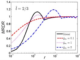
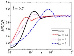
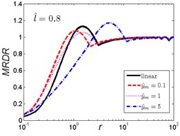
4.2. Maximum relative displacement ratio (MRDR)
The MRDR curves of the nonlinear vibration isolator under rounded displacement step shock excitation of the two cases are shown in Fig. 9 and Fig. 10.
Fig. 9MRDR curves of HSLDS vibration isolator under rounded displacement step excitation varied with shock parameter r when l^ takes a fixed value and y^m varies
a)
b)
c)
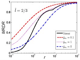
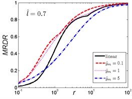
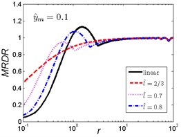
Fig. 10MRDR curves of HSLDS vibration isolator under rounded displacement step excitation varied with shock parameter r when y^m takes a fixed value and l^ varies
a)
b)
c)
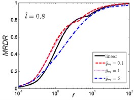
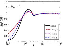
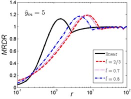
As can be seen in Fig. 9, when the length ratio is fixed, the effect of the magnitude ratio on the performances of the nonlinear vibration isolator under rounded displacement step is almost the same in the three cases. When is a small one (), the MRDR of the nonlinear vibration isolator is always higher than the linear one; but when increases, the trends are opposite, the MRDR of the nonlinear vibration isolator is lower than the linear one when increases to a higher value (), and becomes smaller with the increase of magnitude ratio .
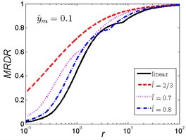
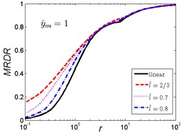
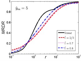
As is shown in Fig. 10, when the magnitude ratio is fixed, the effect of the length ratio on the performances of the nonlinear vibration isolator is not the same in each case. When is a small one (), the MRDR of the nonlinear vibration isolator is always higher than the linear one and decreases with the increase of the length ratio ; when increases, the trends are opposite, the MRDR of the nonlinear vibration isolator is lower than the linear one when increases to a higher value (), the MRDR becomes larger with the increase of length ratio .
The MRDR curves of the nonlinear vibration isolator under rounded displacement pulse shock excitation of the two cases are shown in Fig. 11 and Fig. 12.
Fig. 11MRDR curves of HSLDS vibration isolator under rounded displacement pulse excitation varied with shock parameter r when l^ takes a fixed value and y^m varies
a)
b)
c)
Fig. 12MRDR curves of HSLDS vibration isolator under rounded displacement pulse excitation varied with shock parameter r when y^m takes a fixed value and l^ varies
a)
b)
c)
As can be seen in Fig. 11, when the length ratio is fixed, the effect of the magnitude ratio on the performances of the nonlinear vibration isolator under rounded displacement pulse is almost the same in the three cases, but is different from the rounded displacement step shock excitation. For small parameter , the MRDR of the nonlinear vibration isolator is larger than the linear one; when increases to a certain range, different and corresponds to the different range (e.g, , , ), the MRDR of the nonlinear vibration isolator is lower than the linear one; when continues to increase, the nonlinear vibration isolator can have a higher MRDR over the linear one, the MRDR becomes larger with the increase of magnitude ratio ; when reaches a higher value, the MRDR is more or less the same for both isolators. The peak response of the nonlinear vibration isolator will shift to greater with the increase of magnitude ratio .
As is shown in Fig. 12, when the magnitude ratio is fixed, the effect of the length ratio on the performances of the nonlinear vibration isolator is almost the same in each case. The MRDR of the nonlinear vibration isolator is higher than the linear one except increases to a certain range, and becomes larger with the increase of the length ratio .
The MRDR curves of the nonlinear vibration isolator under oscillatory displacement step shock excitation are similar to the rounded displacement pulse one, so it is no longer described in this paper.
4.3. Maximum acceleration ratio (MAR)
The MAR curves of the nonlinear vibration isolator under rounded displacement step shock excitation of the two cases are shown in Fig. 13 and Fig. 14.
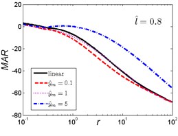
Fig. 13MAR curves of HSLDS vibration isolator under rounded displacement step excitation varied with shock parameter r when l^ takes a fixed value and y^m varies
a)
b)
c)
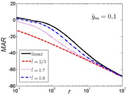
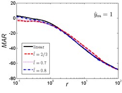
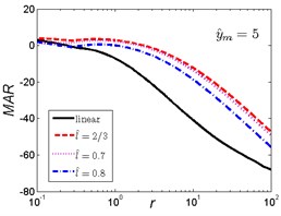
Fig. 14MAR curves of HSLDS vibration isolator under rounded displacement step excitation varied with shock parameter r when y^m takes a fixed value and l^ varies
a)
b)
c)
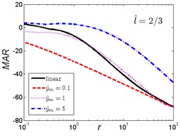
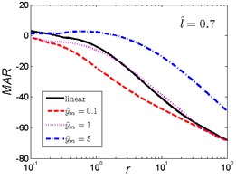
As can be seen in Fig. 13, when the length ratio is fixed, the effect of the magnitude ratio on the performances of the nonlinear vibration isolator under rounded displacement step is almost the same in three cases. When is a small one, the MAR of the nonlinear vibration isolator is lower than the linear one; but when increases, the trends are opposite, the MAR of the nonlinear isolator is higher than the linear one, and becomes larger with the increase of magnitude ratio .
As is shown in Fig. 14, when the magnitude ratio is fixed, the effect of the length ratio on the performances of the nonlinear vibration isolator is not the same in each case. When is a small one, the MAR of the nonlinear vibration isolator is lower than the linear one and becomes larger with the increase of the length ratio . When increases, the trends are opposite, the MAR of the nonlinear vibration isolator is higher than the linear one and becomes larger with the decrease of length ratio .
The MAR curves of the nonlinear vibration isolator under rounded displacement pulse and oscillatory displacement step shock excitations are similar to the rounded displacement step one, so it is no longer described in this paper.
5. Conclusions
In this paper, a nonlinear vibration isolator with HSLDS characteristic comprised of vertical spring and horizontal spring is presented, and the response of the nonlinear vibration isolator under three different kinds of base shock excitations is considered. A closed form solution has been approximated by using a transformation function and ultra-spherical polynomial approximation method, and then compared with numerical results. The compared results show that the method suits for weak nonlinearity, when the nonlinear parameter is a small one, the method gives very well results compared with numerical results and can predict the shock response well; but when the nonlinear parameter increases, the error between analytic and numerical results becomes larger.
Three performance indices are defined to evaluate the performance of the nonlinear vibration isolator and compared with a linear one, results show that the shock performance of the HSLDS vibration isolator depends on not only the performance indices, but also the structural parameters and input shock magnitude. When designing the nonlinear vibration isolator with HSLDS characteristic for shock isolation, the excitation type and input severity parameter should be considered, and choose the structural parameters based on the performance indices and input shock magnitude ratio to satisfy the requirements and provide a better shock isolation performance than the linear vibration isolator.
References
-
Harris C. M., Piersol A. G. Shock and Vibration Handbook. McGraw-Hill, New York, 2002.
-
Rivin E. I. Passive Vibration Isolation. ASME Press, New York, 2003.
-
Alabudzev P., Gritchin A., Kim L., Migirenko G., Chon V., Stepanov P. Vibration Protecting and Measuring Systems with Quasi-Zero Stiffness. Hemisphere Publishing, New York, 1989.
-
Ibrahim R. A. Recent advances in nonlinear passive vibration isolators. Journal of Sound and Vibration, Vol. 314, Issue 3, 2008, p. 371-452.
-
Carrella A., Brennan M. J., Waters T. P. Static analysis of a passive vibration isolation with quasi zero-stiffness characteristic. Journal of Sound and Vibration, Vol. 301, Issue 3, 2007, p. 678-689.
-
Carrella A. Passive vibration isolators with high-static-low-dynamic stiffness. Ph.D. thesis, University of Southampton, 2008.
-
Kovacic I., Brennan M. J., Waters T. P. A study of a nonlinear vibration isolator with a quasi-zero stiffness characteristic. Journal of Sound and Vibration, Vol. 315, Issue 3, 2008, p. 700-711.
-
Carrella A., Brennan M. J., Waters T. P., V. Lopes Jr. Force and displacement transmissibility of a nonlinear isolator with high-static-low-dynamic-stiffness. International Journal of Mechanical Sciences, Vol. 55, Issue 1, 2012, p. 22-29.
-
Zhou N., Liu K. A tunable high-static low-dynamic stiffness vibration isolator. Journal of Sound and Vibration, Vol. 329, Issue 9, 2010, p. 1254-1273.
-
Le T. D., Ahn K. K. A vibration isolation system in low frequency excitation region using negative stiffness structure for vehicle seat. Journal of Sound and Vibration, Vol. 330, Issue 26, 2011, p. 6311-6335.
-
Liu X., Huang X., Hua H. On the characteristics of a quasi-zero stiffness isolator using Euler buckled beam as negative stiffness corrector. Journal of Sound and Vibration, Vol. 332, Issue 14, 2013, p. 3359-3376.
-
Shaw A. D., Neild S. A., Wagg D. J., Weaver P. M., Carrella A. A nonlinear spring mechanism incorporating a bistable composite plate for vibration isolation. Journal of Sound and Vibration, Vol. 332, Issue 24, 2013, p. 6265-6275.
-
Kirk C. L. Non-linear random vibration isolators. Journal of sound and vibration, Vol. 124, Issue 1, 1988, p. 157-182.
-
Kihong Shin Experimental investigation of the vibration transmissibility of a magnet-spring vibration isolator under random excitation. Journal of Vibroengineering, Vol. 16, Issue 4, 2014, p. 1745-1752.
-
Mallik A. K. Principles of Vibration Control. Affiliated East-West Press, New Delhi, 1990.
-
Snowdon J. C. Vibration and Shock in Damped Mechanical Systems. Wiley, New York, 1968.
-
Balandin D. V., Bolotnik N. N., Pilkey W. D. Review: Optimal shock and vibration isolation. Shock and Vibration, Vol. 5, Issue 2, 1998, p. 73-87.
-
Chandra Shekhar N., Hatwal H., Mallik A. K. Response of nonlinear dissipative shock isolators. Journal of Sound and Vibration, Vol. 214, Issue 4, 1998, p. 589-603.
-
Chandra Shekhar N., Hatwal H., Mallik A. K. Performance of non-linear isolators and absorbers to shock excitations. Journal of Sound and Vibration, Vol. 227, Issue 2, 1999, p. 293-307.
-
Liu X., Huang X., Hua H. Performance of a zero stiffness isolator under shock excitations. Journal of Vibration and Control, 2013.
-
Anderson G. L. Application of ultra-spherical polynomials to non-linear, non-conservative systems subjected to step function excitation. Journal of Sound and Vibration, Vol. 32, Issue 1, 1974, p. 101-108.
-
Srirangarajan H. R., Srinivasan P. The pulse response of non-linear systems. Journal of Sound and Vibration, Vol. 44, Issue 3, 1976, p. 369-377.
-
Snowdon J. C. Isolation from mechanical shock with a mounting system having nonlinear dual-phase damping. 41st Shock and Vibration Bulletin, 1970, p. 21-45.
About this article

This work was supported by Aviation Science Foundation of China (Grant No. 2012ZD52054). Also supported by Funding of Jiangsu Innovation Program for Graduate Education (Grant Number KYLX_0243) and the Fundamental Research Funds for the Central Universities.
