Abstract
A single-point fatigue loading system of wind turbine blade driven by an unbalanced shaft was designed. To determine whether the vibrating performance of the loading system satisfied the fatigue test demanding, the blade was driven by different frequency under open-loop control mode in on-site flapwise fatigue test. The results showed that the more the driven frequency close to the blade’s natural frequency, the more the amplitude of the blade increase. In resonance mode, the amplitude of the blade can reach the maximum value certainly. However, the peak values of the vibration have some fluctuation, which will influence the accuracy of fatigue test. To solve the unstable problem of blade’s amplitude, the amplitude of blade’s loading point obtained by laser range meter was taken as the control index, the deviation of the amplitude and its variation tendency were taken as the input and the loading frequency as the output, then an adaptive fuzzy control system based on multistage network was built to realize blade’s constant amplitude vibrating. The on-site test showed the adaptive fuzzy control algorithm put forward in this paper could maintain the error of the peak value of vibration less than 5 mm, which satisfied the fatigue test requirement.
1. Introduction
Wind power generation has many ecological and economic benefits. As an important renewable energy technology, more governments are giving wind power more attention in recent years. A wind turbine generator system is mainly composed of a blade, transmission gear, electric generator, energy storage device, and tower. Since the blade is the main part bearing the wind power, its fine designing, reliable quality, and excellent performance are key factors to ensure the stable operation of a wind turbine generator system [1].
Currently, megawatt (MW) power wind turbines are becoming more popular. As the capacity of these wind turbines increases, the size of the blade must increase accordingly. Thus, larger blades must be designed to have a higher strength and stiffness. Research on blade design and testing becomes more important. A large number of accidents and research results show that fatigue is one of the main failure mechanisms for blades [2-4]. So, fatigue testing of a wind turbine blade is the most effective and reliable method to find weaknesses in a blade’s design.
Fatigue tests on blades are typically conducted by imposing an excitation at the loading point (70 % of the blade length along the spanwise direction) and making the blade and excitation resonate together. It is well known that a structure can be damaged to maximum extent in a resonance state [5]. To reach a resonance state, the designer should firstly supply the bending moment distribution and the number of vibrations. Then the amplitude applied at the loading point, usually called the set amplitude, can be calculated. Finally, the fatigue test is performed under a constant set amplitude loading mode and equivalent quantity of vibrations. According to Li et al. [6] and White [7], a longer vibrating cycle of approximately 106 or more cycles is needed for a fatigue test of megawatt-class wind turbine blades.
Reports about fatigue testing of wind turbine blades are less now. Only a few countries have blade performance testing laboratories, and most fatigue related research focuses on simulation [8-9]. In this paper, a single-point fatigue loading system of a wind turbine blade driven by an unbalanced shaft was developed by collaborating with the Wind Turbine Blade Testing Center at Zhongfu Lianzhong Composite Material Company in Lianyungang, China. By on-site fatigue test under open-loop controlling, the loading system proved capable of resonating the blade and excitation together. However, the amplitude of the blade in the stable stage fluctuated compared to the set amplitude. To eliminate peak error of the vibration, an adaptive fuzzy control frequency system was built to maintain a constant amplitude vibration. The fatigue loading system developed was successfully applied on the fatigue test of an Aeroblade 1.5-40.3 wind turbine blade.
2. Vibration analysis on single-point fatigue loading system
2.1. Designing the single-point fatigue loading system
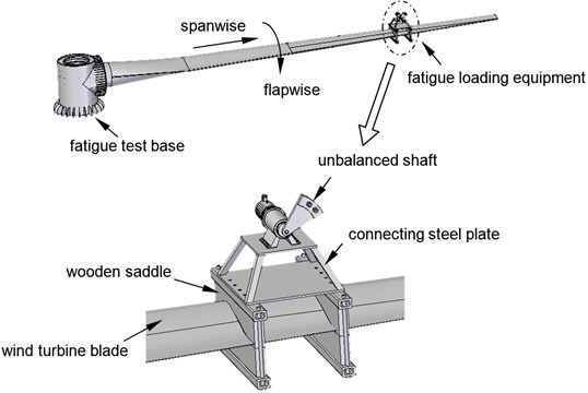
Referring to Risø DTU National Laboratory for Sustainable Energy and U.S. National Renewable Energy Laboratory (NREL) [10], the fatigue loading equipment was mounted at 70 % of the blade length along the spanwise direction. The system included two parts: the fatigue loading equipment and the fatigue test base. The fatigue loading equipment that generated vibrations mainly consisted of an unbalanced shaft, wooden saddle, motor, gear box, and electric control equipment. The fatigue loading equipment and the blade were connected by the wooden saddle and were stuffed with rubber to reduce the strain concentration. The root of the blade was fixed by high strength screw bolts to the barrel-type fatigue test base which was mounted on the ground. The single-point fatigue loading system is shown in Fig. 1.
Fig. 1The structure of a single-point fatigue loading system
2.2. Control system based on multi-level network bus
The power of the tested wind turbine was 1.5 MW and the blade type was Aeroblade 1.5-40.3. This blade is relatively popular in China at present. The length of the blade was 40.3 m and the weight of the blade was 4043 kg. Multi-level network was applied in the control part of the fatigue loading system to transmit data. The connection diagram of network is shown in Fig. 2. Open-loop control mode was adopted to drive the unbalanced shaft.
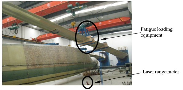
The loading point amplitude was measured real-time in flapwise direction by the laser range meter fixed on the ground. The cycle of the signal acquisition of the laser range meter was less than 33 ms, and the vibration period of the blade was between 1 and 2 seconds. At this resolution, the peak and valley amplitudes were easily identifiable. The on-site test is shown in Fig. 3. Several physical parameters are as follows:
• Power of frequency motor: 22 kW;
• Reduction ratio: 23;
• Controller: Siemens S7-200;
• Frequency motor: Shenyuan SY5000-G;
• Weight of the unbalanced shaft: 350 kg.
Equivalent arm length of unbalanced shaft: 0.8 m.
Fig. 2Control diagram of multi-level network
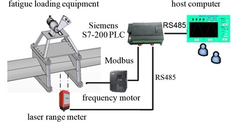
Fig. 3On-site wind turbine blade fatigue loading test
2.3. Vibrating analysis
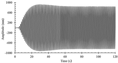
Three rotary driving speeds of the unbalanced shaft were selected: 45.6 RPM, 47 RPM, 46.5 RPM. The speed () of the unbalanced shaft caused resonance. The blade amplitude variations are shown in Fig. 4.
The rotary driving speed was 45.6 RPM. At this speed, the frequency was less than the natural frequency of the blade. After 10 s, the amplitude of the wind turbine blade dramatically increased, see Fig. 4(a). Approximately 24 s later, the excitation force impeded the vibration of the blade which caused the amplitude to decrease. After 70 s, the amplitude began to stabilize. After a period of several small fluctuations, the amplitude stabilized at approximately 350 mm.
In Fig. 4(b), the rotary driving speed was 47 RPM. At this speed, the frequency was larger than the natural frequency of the blade. At approximately 5 s, the amplitude of the blade also increased dramatically and gradually stabilized after minor fluctuations. Due to the small deviation between the rotary driving frequency and the natural frequency of the blade, the blade amplitude stabilized at approximately 800 mm.
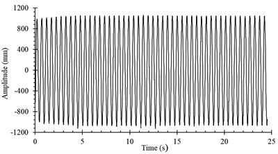
In Fig. 4(c), the rotary driving speed was 46.5 RPM. At this speed, the frequency equaled the natural frequency of the blade forming the resonance condition. The amplitude of the blade increased dramatically and stabilized at approximately 1000 mm. In the steady state, the amplitude of the blade fluctuated.
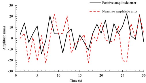
To obtain the fluctuation error of amplitude in resonance condition, amplitudes of some vibrating cycles were compared to the set amplitude. The amplitude error for a given range is shown in Fig. 5. The maximum amplitude error was 23 mm. The amplitude error influences the accuracy of the fatigue loading test. Amplitude error arises from inaccurate measurement of the natural frequency of the blade. Therefore, matching the rotary driving frequency with the natural frequency of the blade becomes difficult.
Fig. 4Amplitude variations of loading point on blade: a) n1= 45.6 RPM, b) n2= 47.0 RPM, c) n3= 46.5 RPM
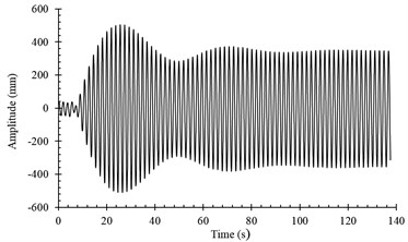
a)
b)
c)
Fig. 5Peak errors for a given range of time
3. The design of an adaptive frequency controller
3.1. Fuzzy control regulation
Traditional controlling theory can control accurate systems well. However, it is incapable for complicated systems difficult to build dynamical model. From the vibrating analysis of blade mentioned above, we can see that the vibration of fatigue loading test is non-linear. The output variable (the blade amplitude) does not be linear with the input variable (the motor frequency). Furthermore, the dynamical model of vibration is complicated and difficult to inflect the dynamic state of whole vibration system, see [11]. Fuzzy control is essentially a kind of non-linear controlling method and it belongs to the category of intelligent control. Fuzzy control is widely applied to the field that the dynamic behavior of system cannot be described correctly.
To improve the accuracy of fatigue loading test, an adaptive frequency controller based on fuzzy control theory was designed to make the wind turbine blade stay continuously in the resonance condition. In the resonance condition, the blade maintained stable amplitude. The controller was a double inputting and single outputting system. The two input variables were the 1) error and 2) rate of change of the error between the measured amplitude and the set amplitude. The single output variable was the driving frequency.
For the input variables of the fuzzy controller, the amplitude’s error and its rate of change were divided into 7 levels: very small (PB), small (PM), a little small (PS), medium (ZE), a little big (NS), big (NM) and very big (NB) [12]. Since the blade was expected to have constant amplitude in fatigue loading test, the membership function of input variables used a symmetrical triangle function. The membership function is given by Eq. (1), where [, ] is the supported domain of the function. The membership function for the output variable was the same as input variables. However, the number of grade level was different according to the characteristics of each variable:
Anti-fuzzy adopted the centroid method. The centroid method takes the basic variable corresponding to the center of gravity of the area as the crisp value. The area mentioned above was enclosed by a fuzzy set membership function and basic variable axis. Centroid method is expressed by:
where is the crisp output variable, is the output variable, is the membership function of fuzzy set, is the lower limit of crisp value, and is the upper limit of crisp value [13].
The Mamdani decision method was adopted as the fuzzy decision. If the measured amplitude of the loading point was small compared to the set amplitude, and the rate of change of the measured amplitude was large, then the driving frequency was increased. When the amplitude remained relatively stable (within the same level) and the rate of change was insignificant, the driving frequency was held constant. Fuzzy rules were established, see Table 1. The variables and were the amplitude error and rate of change of the error between the measured amplitude and the set amplitude. According to the previous classifications of inputs and outputs, a total of 49 fuzzy control rules were established.
Table 1Fuzzy control regulation of frequency
NB | NM | NS | ZE | PS | PM | PB | |
NB | PB | PB | PB | PM | PM | PM | NS |
NM | PB | PB | PM | PM | PM | PS | NS |
NS | PB | PM | PM | PS | PS | NS | NS |
ZE | PM | PM | PS | ZE | NS | NM | NB |
PS | PS | PS | NS | NS | NM | NS | NB |
PM | PS | NS | NM | NM | NM | NS | NB |
PB | PS | NM | NM | NM | NB | NB | NB |
3.2. Fatigue loading test under adaptive fuzzy control
The connection diagram of the network is shown in Fig. 2. Closed-loop control mode was adopted to drive the unbalanced shaft and the adaptive fuzzy control algorithm mentioned above was applied in the control system. In closed-loop control mode, the discrete domains of the amplitude errorand rate of change in amplitude error were [–28 mm, 28 mm] and [–14 mm, 14 mm], respectively. The 7 levels of and are given in Table 2.
Table 2Levels of amplitude error (e) and rate of change in amplitude error (∆e)
NB | NM | NS | ZE | PS | PM | PB | |
[20, 28) | [12, 20) | [4, 12) | [–4, 4) | [–12, –4) | [–20, –12) | [–28, –20) | |
[14, 10) | [6, 10) | [2, 6) | [–2, 2) | [–2, –6) | [–6, –10) | [–14, –10) |
The amplitude signals were fed back real-time to the controller by the RS485 bus. The controller compared the actual amplitude value with the set value and modified the output frequency of the motor continually by adaptive fuzzy algorithm so that the blade and the loading equipment could resonate with the stable amplitude.
Through the Modbus, there was bidirectional data transmission between the controller and the frequency motor. Through RS485 bus, the controller transmitted the current feedback data to upper monitor which displayed information real-time. Due to the large amount of data acquired, the upper monitor saved the current amplitude and loading frequency applying the Access database.
In order to test the performance of the algorithm, four stages (stable-stop-start-stable) were used to observe amplitude variations of the blade. The curves of those phases are shown in Fig. 6. With the controlling of adaptive fuzzy algorithm, the loading point of blade was in a constant-amplitude vibration state and the blade’s amplitude remained at approximately 1 m in the steady state.
Fig. 6Blade amplitude variation on multi-stag
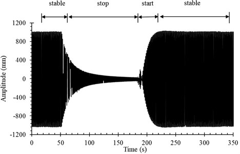
In stop stage, since there was no external power supplied, the blade’s amplitude decreased rapidly. In start stage, the blade’s amplitude increased rapidly. In order to present the variation of the blade’s amplitude more clearly, an enlarged view of the amplitude curve’s start stage is shown in Fig. 7. In approximately 20 vibration periods, the blade’s amplitude increased to the set value under the adaptive frequency controlling.
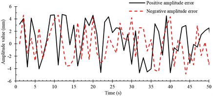
In the stable vibration stage, some peak values were compared to the set value. Amplitude errors for a given region are shown in Fig. 8. According to the error curves in the stable stage, all the upper and lower peak errors were less than 5 mm. This proved that the adaptive fuzzy control algorithm modified the driving frequency automatically while maintaining the blade in the resonance condition.
Fig. 7Amplitude variation in start stage
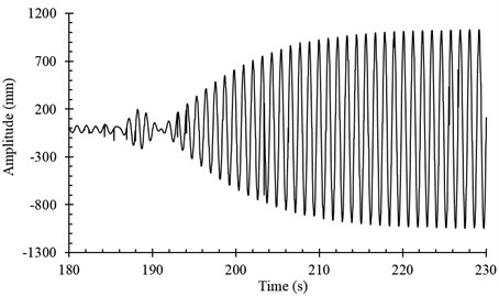
Fig. 8Peak errors for a given region of time
4. Conclusions
A fatigue loading test for MW wind turbine blades driven by an unbalanced shaft was designed based on an adaptive fuzzy control algorithm. Conclusions can be drawn as follows:
1) When a fatigue test was conducted under an open-loop control mode and the driving frequency was close to the natural frequency of the blade, the amplitude of the wind turbine blade dramatically increased. The value of the amplitude at stable stage depended on the close degree of the driving frequency to the natural frequency of the blade.
2) When the driving frequency under open-loop control mode was similar to the natural frequency of the blade forming the resonation, the amplitude reached the maximum value at stable stage. However, the amplitude has some fluctuation error because the driving frequency could not exactly match the natural frequency of the blade.
3) When the fatigue test was conducted in a closed-loop control mode, the applied adaptive fuzzy control algorithm guaranteed continuous resonation of the blade with relatively constant amplitude. This decreased the experimental period and improved the accuracy of the fatigue test.
4) The results of the fatigue test proved that the loading system developed in this article maintained the wind turbine blade’s amplitude error at less than 5 mm. Thus, an effective dynamic test method for the fatigue test of a wind turbine blade was provided.
References
-
Herbert G. M., Iniyan S., Revnalsan E. A review of wind energy technologies. Renewable Sustainable Energy Reviews, Vol. 11, Issue 6, 2007, p. 1117-1145.
-
Ackermann T., Soder L. Wind energy technology and current status. Renewable & Sustainable Energy Reviews, Vol. 4, 2000, p. 315-374.
-
Han Y. Q., Lü L. Y., Xing X. B. Research on analysis method of fatigue strength in wind blade boot. Energy Engineering, Vol. 3, 2009, p. 33-36.
-
Guo L., Wang W. Q., Ying X., He S. A system of wind turbine fatigue loads measurement based on virtual instruments. Acta Energiae Solaris Sinica, Vol. 29, Issue 3, 2008, p. 349-353.
-
Li D. Y., Ye Z. Q., Chen Y., et al. Fatigue life analysis of the glass reinforced plastic blade of horizontal axis wind turbine. Acta Energiae Solaris Sinica, Vol. 25, Issue 5, 2004, p. 592-597.
-
Li D. Y., Ye Z. Q., Chen Y., Bao N. S. Load spectrum and fatigue life analysis of the blade of horizontal axis wind turbine. Engineering Mechanics, Vol. 21, Issue 6, 2004, p. 118-123.
-
White D. New method for dual-axis fatigue testing of large wind turbine blades using resonance excitation and spectral loading. Technical Report, National Renewable Energy Laboratory, Golden, Colorado, 2004.
-
Zhou P. Z., Zeng J. C., Xiao J. Y., et al. Aerodynamic analysis of a large-scale wind turbine blade based on bladed software. Journal of Central South University, Vol. 41, Issue 5, 2010, p. 2022-2027.
-
Kong C., Band J., Sugiyama Y. Structural investigation of composite wind turbine blade considering various load cases and fatigue life. Wind Energy, Vol. 30, 2005, p. 2101-2114.
-
Kristensen O. J. D., Jørgensen E. R. Accelerated fatigue testing of LM 19.1 blades. Technical Report, Risø National Laboratory, Roskilde, Denmark, 2003.
-
Zhang L. A., Huang X. M. Design modeling and test of mw wind turbine blade fatigue loading system. Acta Energiae Solaris Sinica, Vol. 34, Issue 9, 2013, p. 1556-1560.
-
Bai J. B., Zhang X. S., Liu Q. J. Research on fuzzy PI adaptive controller in air-conditioning systems. Ciesc Journal, Vol. S2, Issue 61, 2010, p. 99-106.
-
Zhang J. H., Han J. L. Airfoil control surface LCO suppression with fuzzy logic control. Journal of Vibration and Shock, Vol. 31, Issue 6, 2012, p. 50-61.
About this article

This work is sponsored by National Natural Science Foundation of China (No. 51305243) and partially supported by the Taishan Scholar Program.
