Abstract
Several modern engineering materials are difficult to process with conventional machining methods. Ultrasonically assisted turning (UAT) is a novel machining technique, where high frequency vibration is superimposed on the cutting tool. Compared to conventional turning (CT), it demonstrated a range of benefits in processing many intractable materials. A decrease in the average cutting force, an improvement in the surface finish and noise reduction were observed. In this study a Lagrangian smoothed particle hydrodynamics (SPH) was introduced for the modeling of the vibro-assisted turning of this advanced alloy. The UAT was implemented into the model by using the user interface VUAMP, available in ABAQUS/Explicit. The model was validated with experimental data available in the literature. The influence of vibration parameters (i.e. amplitude and frequency) on the process variables such as cutting force, chip morphology, distribution of stresses and temperatures in the workpiece was investigated thoroughly.
1. Introduction
Ultrasonically-assisted turning (UAT) is an advanced machining technique, where high frequency vibration is superimposed on a cutting tool. Compared to conventional turning (CT), it allows significant improvements in the processing of many intractable materials such as high-strength aerospace alloys and composites by producing a noticeable decrease in cutting forces and a superior surface finish [1-3].
Over the last two decades, a significant amount of work has been carried out to elucidate the underlying mechanics of this process. Babitsky et al. [4] demonstrated improvements in the surface quality for UAT when compared with CT. Mitrofanov et al. [1] and Ahmed et al. [2] developed 2D and 3D FE model of UAT, respectively and investigated the influence of process parameters on the deformation response of the workpiece material. Volkov et al. [5] did energy-based analysis of UAT analytically based on the incubation-time concept and employing methods of fracture mechanics. Nategh et al. [6] developed an analytical model to investigate the kinematics of the ultrasonic-vibration assisted oblique turning. Study in [7] was dedicated for optimization of tool structure in vibration cutting. Maurotto et al. [8] introduced an improved UAT setup for a Ti alloy achieving substantial reductions in the cutting forces and a concomitant improvement in the surface quality. Recently, hot ultrasonically-assisted turning (HUAT) was introduced by Muhammad et al. [9] by combining conventional hot turning (HCT) with UAT. This enhancement enabled a significant reduction in cutting forces, often in excess of 80-85 % when compared with CT.
Numerical simulations are useful tools as they reduce effort in doing extensive experimentation when an adequate modeling framework is created. They are used in machining processes to study various physical mechanisms underpinning a material’s response to dynamic loads. This allows to interrogate stresses and temperatures of the process zone close to the cutting tool-workpiece interaction zone which is generally not possible in experimentations due to the opaque nature of the workpiece material [9]. Mesh-based and particle-based methods are two wide-used types of modeling frameworks used in machining simulations. In the first finite element based framework, Lagrangian, Eulerian and arbitrary Lagrangian-Eulerian are commonly used approaches. Each method has its own limitations. For instance, in the Eulerian approach it is not possible to accurately monitor the evolution of the process zone and due to a prior assumption of the chip shape, free boundaries of the chip cannot be predicted naturally via simulations. On the other hand, in Lagrangian-based approaches, severe deformation of the material in front of the tool edge leads to heavily distorted elements, often causing simulations to terminate prematurely. This calls for automatic remeshing techniques for simulaton fidelity. Research into robust remeshing techniques is ongoing [10].
The Smooth Particle Hydrodynamics (SPH) is a point based Lagrangian numerical method developed by Lucy [11], and Monaghan and Gingold [12] to avoid the limitations of traditional finite element techniques. In SPH, the prescribed set of continuum equations is discretized by interpolating the properties directly at a discrete set of points distributed over the solution domain without defining a spatial mesh [13]. There are several advantages using SPH method in machining simulations. For instance the particles move relative to each other in a disordered way during the deformation, i.e. particles are rearranged without topological restriction, thus, remeshing is not required. That also lead to the formation of free surfaces through the natural flow of the workpiece material around the tool tip, i.e. a natural separation occurs between chip and the workpiece. This method has attracted the attention of computational material engineering community in recent years. For instance Limido et al. [14] developed the two-dimensional SPH modelling of high speed cutting and investigated the influence of model parameters on the numerical results. Chen and Kulasegaram [15] investigated the fracture of particulate composites using this method. Recently Zahedi et al. [16] and Xi et al. [17] used the combination of SPH and FE methods to investigate the orthogonal micro-machining of f.c.c. single crystal and thermally assisted machining of Ti alloy, respectively.
In this study we developed an adiabatic three-dimensional SPH modelling of ultrasonically-assisted turning of a titanium-based beta-alloy. To the best of the author’s knowledge this is the first study of the UAT process in the literature investigating the influence of vibration parameters (i.e. amplitude and frequency) on the process variables such as cutting force, chip morphology, distribution of stresses, and temperatures in the workpiece. Ultimately, this work enables us to elucidate the underlying deformation mechanism in UAT.
The paper is organized as follows: the Lagrangian formulation of SPH method is presented in Section 2. Section 3 details the developed SPH modelling of UAT of Ti-based alloy. Validation of the model against experimental data and its predictive capabilities with related discussions are provided in Section 4. The paper ends with some concluding remarks in Section 5.
2. Smoothed particle hydrodynamics
In SPH method, due to the absence of the grid, the computational framework is the particles where the governing equations are resolved. In this method, a kernel (smoothing) formulation is used to estimate the value of a continuous function or its spatial derivatives on a particle based on known values on the surrounding particles, whereas in conventional Lagrange or Euler FE methods, connectivity between nodes is required for the calculations.
In SPH method, the scalar function of the three-dimensional position vector is defined as:
where is the volume of the integral that contains , is the position of the neighbourhood of the point , is a smoothing kernel function and is the smoothing length varying temporally and spatially. The cubic-spline integral approximation is most commonly used type in SPH method for the definition of . This function also satisfies the following conditions:
where is the Dirac delta function, is a constant defining the effective area of .
The discrete form of for the set of material particles representing the discretized continuum, the so-called particle approximation, can be written as follows:
where, is the number of neighbouring particles, and are the mass and density of the each particle, respectively. According to Eq. (3), is estimated using the average of those values of the function at all the particles in the support domain of this particle weighted by the smoothing function. Consequently, the conservation equations for mass, momentum and energy in their discrete form can be written as follows, respectively:
where and are the space indices, , , are the momentum, energy, stress values of particle , respectively, .
The SPH computational framework, available in ABAQUS/Explicit [13], was used in the following analysis. In SPH method the calculation steps are similar to FE method except the Kernel approximations are used to compute forces and strain rates from the spatial derivatives of stresses and velocity, respectively [14].
3. SPH model of ultrasonically-assisted turning
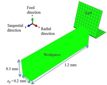
A three-dimensional explicit SPH model of CT and UAT was created using the commercial software ABAQUS 6.13 [13] (Fig. 1(a)). The dimensions of the workpiece used in simulations are 1.2 mm in length, 0.3 mm in height and 0.2 mm in width. The SPH domain was discretized with one-node PC3D particle elements. Our first analysis demonstrated that 36864 particles per cm3 of the workpiece sample, where the distance between two adjacent particles was 12.5 μm, was sufficient in obtaining convergence in the average cutting force value, hence this particle resolution was considered in the simulations. A fixed boundary condition was imposed on the bottom and left-hand face of the workpiece (Fig. 1(a)). The tool with a rake angle of 14.5°and a cutting edge radius of 25 μm is considerably stiffer than the studied workpiece, hence, is modelled as a rigid body. Its geometry was discretized into 190 four-node rigid elements (R3D4) with a refined mesh at the tip. Coulomb’s friction law with a friction coefficient of 0.6 was used to model the interaction between the tool and the workpiece material.
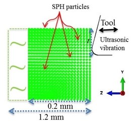
The relative movement between the tool and workpiece in CT is simulated by translation of the tool with a constant velocity () of 10 m/min. A depth of cut () of 200 μm and a constant feed rate of () 100 μm/rev were considered in the simulations. In UAT harmonic ultrasonic vibration with a vibration amplitude () ranging from 8 μm to 32 μm (peak-to-valley) and frequency () ranging from 10 kHz to 30 kHz is superimposed on the tool movement in the tangential direction (i.e. along -axis in Fig. 1(b)). Summary of the cutting parameters used in the SPH simulations is presented in Table 1.
Fig. 1a) 3D SPH model of the cutting process, b) relative movement of the workpiece and cutting tool (shown on the y-z plane) in simulations of UAT
a)
b)
Table 1Cutting parameters used in the SPH simulations
Parameters | Magnitude |
Cutting speed, (m/min) | 10 |
Depth of cut, (μm) | 200 |
Feed rate, (μm/rev) | 100 |
Frequency, (kHz) | 10, 20, 30 |
Amplitude, (μm) | 8, 16, 24, 32 |
Initial temperature, (°C) | 27 |
The tool displacement in UAT equals to , where the first term represents the tool displacement for CT (). The variation of tool displacement with time for CT and UAT analysis is presented in Fig. 2. Consequently, velocity of the tool in UAT can be expressed as In this enhanced process cutting occurs with multiple-impact interactions entailing a condition for the separation of the tool from workpiece material within each cycle of ultrasonic vibration [3]. This requires that the vibration velocity (a) should be larger than . This condition is satisfied in the present parameter setting. UAT was implemented into the SPH model by using user interface VUAMP, available in ABAQUS/Explicit.
A titanium-based beta-alloy Ti-15V-3Al-3Cr-3Sn (in short: Ti-15-3-3-3) was used as a workpiece material. Such alloys are used in the aerospace and other advanced engineering fields because of their high strength and toughness, light weight, extraordinary corrosion resistance, and ability to withstand extreme temperatures. The material parameters used in the simulation are tabulated in Table 2. Multi-linear material model was used to represent the response of the Ti-15-3-3-3 in post-elastic regime at various strain-rates and temperatures. The details of the data can be found elsewhere [9, 18-19].
As the thermal conductivity of Ti-15-3-3-3 is very low for a metal and the machining process is so rapid that the heat due to mechanical deformation has no time to diffuse through the material, an adiabatic thermal-stress analysis was used in the simulations. The workpiece was assumed to have an initial temperature of 20°C. It was assumed that there was no heat conduction between the tool and the workpiece.
Fig. 2Displacement-time relationship for the cutting tool in CT and UAT analysis
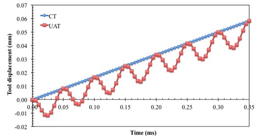
Table 2Material properties of Ti-15-3-3-3 [9]
Density (kg m-3) | 4900 |
Specific heat (J kg-1K-1) | 600 |
Thermal conductivity (W m-1K-1) | 8.10 |
Inelastic heat fraction | 0.9 |
Coefficient of thermal expansion (K-1) | 8.4 10-6 |
Young’s modulus (GPa) | 87 |
Poisson’s ratio | 0.3 |
4. Results and discussion
In this section the results obtained from SPH simulations of CT and UAT of Ti-15-3-3-3 including their validation against experimental data are presented and discussed extensively.
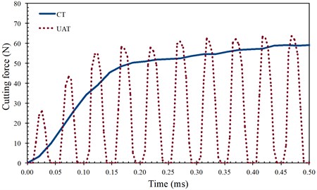
Fig. 3Comparison of force history acting on the cutting tool a) and average cutting forces in tangential direction b) for CT and UAT simulations (a= 8 μm, f= 20 kHz)
a)
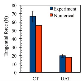
b)
One of the main parameters characterising the tool-workpiece interaction is the cutting force as it reflects a global response of the deformed material. A reduction in cutting force would result in improved surface finish, extension of the tool life and an increase in the amount of the material removed in unit time [3]. Fig. 3(a) demonstrates the change in the magnitude of cutting force in CT and UAT processes with an increase of tool penetration. It is noted that in CT with an increase of tool displacement, firstly an increasing cutting force is exerted on the tool (from 0 to 0.16 ms) followed by a region in which the force increase is significantly curtailed [20]. Indeed it seems that the force magnitude saturates to a constant magnitude with increasing cutting time. This is due to the size of the contact length between tool and workpiece. The cutting force for CT reaches its constant value when the length of the tool-workpiece interface has reached its stationary, non-changing size [21]. On the other hand in UAT the cutting force consists of many cycles following each other, where the maximum cutting force of each cycle increases firstly with an increase of deformation followed by an almost constant force magnitude (in the average sense), similar to CT. Within each single cycle of vibration, the cutting force start increasing with penetration from the moment of the first contact with the chip and attain a level higher than the average force in CT when the tool reaches the maximum penetration depth. The force magnitude then starts declining at the unloading stage until it vanishes when the tool separates from the process zone and starts moving away from it. Fig. 3(b) demonstrates the tangential component of the average cutting force values obtained by SPH simulations and experiments [9] for CT and UAT. Overall the numerical results are in good agreement with obtained experimental values. Numerical results proved the reductions in the average cutting force by the introduction of UAT. Namely, a drop in average cutting force of 62 % was observed for the change of turning mode from CT to UAT in tangential direction.
The current model enables us to study the influence of vibration parameters (i.e. amplitude and frequency) on the process variables such as cutting force, chip morphology and distribution of stresses, and temperatures in the workpiece. Fig. 4(a) presents the variation in cutting force for a single cycle of vibration for different -values (8 μm, 16 μm, 32 μm). An increase in the peak force within a shorter perid of contact, where the extent of separation between the tool and workpiece in one complete cycle increased, was observed with an increase in amplitude. This resulted in higher impact imposed by tool to the workpiece for a larger -value due to increased level of the relative velocity of the cutting tool for a given frequency of ultrasonic vibration. It was observed that with an increase in a decrease in the average cutting force occurred for the same cutting conditions (Table 3) [3].
Fig. 4Cutting force history acting on the cutting tool at various amplitudes a) and frequencies b) of vibration in UAT analysis
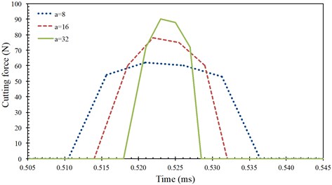
a)
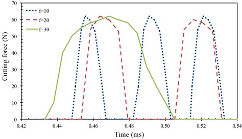
b)
Fig. 5 presents the distribution of stress and temperature on the - plane of the workpiece at the moment where the cutting force reaches its peak value in a single vibratory cycle post average force saturation. For comparison purposes, distributions for CT is also presented. In CT as the cutting tool is permanently in contact with the workpiece a non-changing stress and temperature distribution is observed after the initial tool engagement with the workpiece. In UAT the stresses attain levels somewhat higher than in CT when the tool reaches the maximum penetration depth; with tool retraction the stress levels in the workpiece drops below than of CT [2].
Table 3Average cutting forces at various amplitudes and frequencies of vibration in UAT analysis
Parameters | Average cutting force (N) | |
20 kHz | 8 μm | 20.4 |
16 μm | 16.4 | |
32 μm | 12.8 | |
8 μm | 10 kHz | 23.4 |
20 kHz | 20.4 | |
30 kHz | 17.5 | |
Fig. 5Distribution of von Mises stress and temperature in the workpiece for CT and UAT analysis with various a value (f= 20 kHz) at an instant where the cutting force reached its peak (at maximum penetration) around t= 1.18 ms
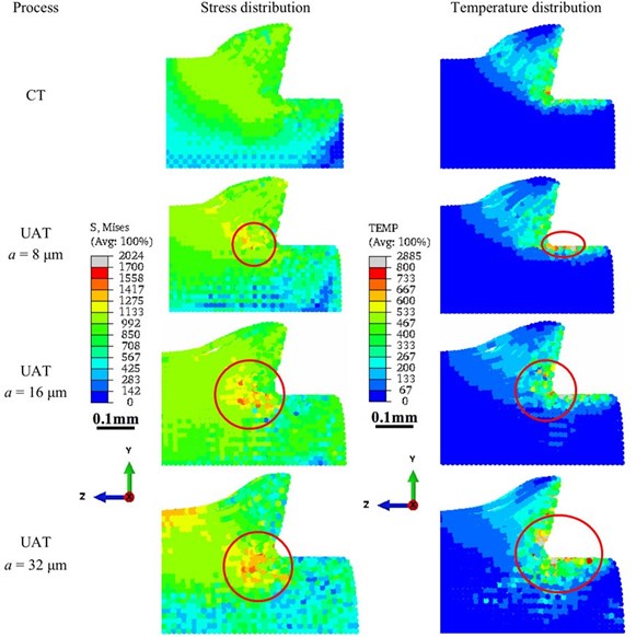
Fig. 5 demonstrates that in CT while an increase in the stress was observed not only in the primary deformation zone and in the chip but also in the far-field, an increase in the temperature occured only in the primary deformation zone and in the chip during the deformation. When the turning mode was changed from CT to UAT, for 8 μm, though the stress and temperature distribution do not change significantly, we observe some localized regions of high stresses and temperature (marked in red circle in Fig. 5). When was increased to 16 μm, an increase in the localized area was observed for both fields. For 32 μm, the localization became more prominent while far-fields in the workpiece experienced an increasing temperature. These observations demonstrated that an increase in value in UAT converted this process into a more impact-type deformation than a conventional cutting, which, in turn, led to localized stress and temperature distribution in the workpiece.
We also investigated the chip morphology for CT and UAT with different values. For detailed analysis, we considered larger cutting length in the simulations. Fig. 6 presents the respective chip shapes. We observed that while the chip morphologies for CT and UAT with 8 μm were similar, thinner chips were observed for UAT with 16 μm, 24 μm and 32 μm. We calculated the chip compression ratio (ratio of post-turning chip thickness to undeformed chip thickness) for all the cases investigated (Table 4). The chip compression ratio was ~1.60 for CT and UAT with 8 μm, while it was 1.52, 1.37 and 1.15 for UAT with 16 μm, 24 μm and 32 μm, respectively. The results demonstrated that the amplitude of vibration in UAT influenced the chip morphology significantly.
Fig. 6Obtained chip morphology in CT and UAT analysis (shown on the y-z plane) with various a values (f= 20 kHz) at t= 3 ms

a) CT

b) UAT, 8 μm

c) UAT, 16 μm

d) UAT, 24 μm

e) UAT, 32 μm
Table 4Chip compression ratio in CT and UAT analysis with various a values (f= 20 kHz) at t= 3 ms
Process | Chip compression ratio | |
CT | 1.63 | |
UAT | 8 μm | 1.59 |
16 μm | 1.52 | |
24 μm | 1.37 | |
32 μm | 1.15 | |
Fig. 7Distribution of von Mises stress and temperature in the workpiece for CT and UAT analysis with various f values (a= 8 μm) at an instant where the cutting force reached its peak (at maximum penetration) around t= 1.21 ms
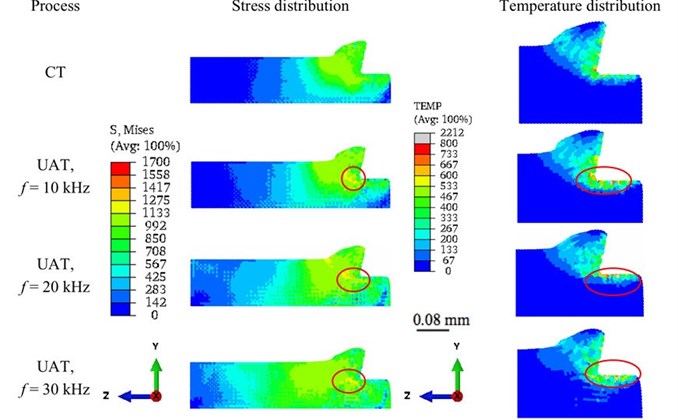
Then, we investigated the influence of vibration frequency () on the numerical results. Three levels of frequency (10 kHz, 20 kHz, 30 kHz) were analysed in SPH simulations. We found that with an increase in f, tool separation from the workpiece was accelerated. Fig. 4(b) presents the variation in cutting force for different values. The peak force remained nearly at the same level in all studied cases, but the average force decreased when frequency increased from 10 to 30 kHz (Table 3) [3]. Fig. 7 presents the distribution of stress and temperature on the - plane of the workpiece for CT and UAT (at the instant where the cutting force reaches its peak value) for different values. It was observed that when the cutting mode was changed from CT to UAT, larger far-field areas in the workpiece attained higher stress values and this was more prounced when the frequency of vibration was increased. Since UAT is a vibro-impact process, localization in the stress and temperature distribution was observed. Interestingly, a change in value did not influence the chip morphology.
5. Concluding remarks
In this study we have developed an adiabatic three-dimensional explicit SPH model for the vibro-assisted turning of a Ti-based alloy. Due to the absence of a fixed mesh in the SPH method, large deformations and workpiece-chip separation are resolved in a natural way. Thus, the technique provides an alternative to conventional finite element method for the numerical simulation of the machining simulations. The numerical results obtained from simulations were in good agreement with experimental data obtained previously. Notably, a significant reduction in the average cutting force was observed in UAT when compared to CT technique.
Our simulations demonstrated that when the cutting mode was changed from CT to UAT, localized stress and temperature distribution in the workpiece increased significantly. The main reason for the increase in the stress and temperature in the process zone especially in the localized regions was the additional amount of energy supplied to the cutting tool in UAT. We observed that while the magnitude of vibration amplitude influenced the chip morphology, the influence of its frequency on the chip shape was negligible.
References
-
Mitrofanov A., Babitsky V., Silberschmidt V. V. Finite element modelling of ultrasonically assisted turning of Inconel 718. Journal of Materials Processing Technology, Vol. 153-154, 2004, p. 233-239.
-
Ahmed N., Mitrofanov A. V., Babitsky V. I., Silberschmidt V. V. 3D finite element analysis of ultrasonically assisted turning. Computational Materials Science, Vol. 39, 2007, p. 149-154.
-
Ahmed N., Mitrofanov A. V., Babitsky V. I., Silberschmidt V. V. Analysis of forces in ultrasonically assisted turning. Journal of Sound and Vibration, Vol. 39, 2007, p. 149-154.
-
Babitsky V., Mitrofanov A., Silberschmidt V. Ultrasonically assisted turning of aviation materials: simulations and experimental study. Ultrasonics, Vol. 42, 2004, p. 81-86.
-
Volkov G. A., Bratov V. A., Gruzdkov A. A., Babitsky V. I., Petrov Y. V., Silberschmidt V. V. Energy-based analysis of ultrasonically assisted turning. Shock and Vibration, Vol. 18, 2011, p. 333-341.
-
Nategh M. J., Razavi H., Abdullah A. Analytical modelling and experimental investigation of ultrasonic-vibration assisted oblique turning, part1: Kinematics Analysis. International Journal of Mechanical Sciences, Vol. 63, 2012, p. 1-11.
-
Ostasevicius V., Gaidys R., Gyliene V., Jurenas V., Daniulaitis V., Liepinaitis A. Passive optimal tool structures for vibration cutting. Journal of Vibroengineering, Vol. 13, 2011, p. 769-777.
-
Maurotto A., Muhammad R., Roy A., Silberschmidt V. V. Enhanced ultrasonically assited turning of a β-titanium alloy. Ultrasonics, Vol. 53, 2013, p. 1242-1250.
-
Muhammad R., Maurotto A., Demiral M., Roy A., Silberschmidt V. V. Thermally enhanced ultrasonically assited machining of Ti alloy. CIRP Journal of Manufacturing Science and Technology, Vol. 7, 2014, p. 159-167.
-
Movahhedy M., Gadala M. S., Altintas Y. Simulation of the orthogonal metal cutting process using an arbitrary Lagrangian-Eulerian finite-element method. Journal of Materials Processing Technology, Vol. 103, 2000, p. 267-275.
-
Lucy L. B. A numerical approach to the testing of the fission hypothesis. The Astronomical Journal, Vol. 82, 1977, p. 1013-1024.
-
Monaghan J. J. Smoothed particle hydrodynamics. Reports on Progress in Physics, Vol. 68, 2005, p. 1703-1759.
-
Systemes D. Abaqus 6.13 Analysis User Manual, 2013.
-
Limido J., Espinosa C., Salaun M., Lacome J. L. SPH method applied to high speed cutting modelling. International Journal of Mechanical Sciences, Vol. 49, 2007, p. 898-908.
-
Chen Y., Kulasegaram S. Numerical modeling of fracture of particulate composites using SPH method. Computational Materials Science, Vol. 47, 2009, p. 60-70.
-
Zahedi S. A., Demiral M., Roy A., Silberschmidt V. V. FE/SPH modeling of orthogonal micro-machining of f.c.c. single crystal. Computational Materials Science, Vol. 78, 2013, p. 104-109.
-
Xi Y., Bermingham M., Wang G., Dargusch M. SPH/ FE modelling of cutting force and chip formation during thermally assisted machining of Ti6Al4V alloy. Computational Materials Science, Vol. 84, 2014, p. 188-197.
-
Demiral M., Roy A., Silberschmidt V. V. Effect of loading conditions on deformation process in indentation. Computers Materials and Continua, Vol. 19, 2010, p. 199-216.
-
Muhammad R., Ahmed N., Roy A., Silberschmidt V. V. Numerical modeling of vibration-assisted turning of Ti-15-333. Procedia CIRP, Vol. 1, 2012, p. 347-352.
-
Zorev N. N., Shaw M. C. Metal Cutting Mechanics. Pergamon Press, USA, 1996.
-
Demiral M., Roy A., Silberschmidt V. V. Deformation processes of advanced alloy in indentation and turning. Computers Materials and Continua, Vol. 31, 2012, p. 157-171.
About this article

The research leading to these results received funding from KAUST baseline fund.
