Abstract
For enhancing drilling efficiency and controlling drilling direction, it is necessary to predict and control dynamic behavior of drilling mechanism effectively. In view of the coupling vibration and low drilling efficiency of auger drilling machine, a dynamic coupling model of multi-drilling mechanism was established to analyze the vibration characteristics under different coal hardness, drilling depths and rotating speeds. Simultaneously, the vibration tests of drilling process were conducted on the coal cutting test bed, and the results correspond with the simulation results. The results show that: the vibration displacement magnitude and fluctuation of multi-drilling mechanism increase with the coal hardness, while decrease then increase with the drilling depth, and increase then decrease with the rotating speed. The increases of coal hardness and drilling depth result in difficulty for coal cutting. The cutting torque decreases with rotating speed, while there is little influence on the feeding resistance.
1. Introduction
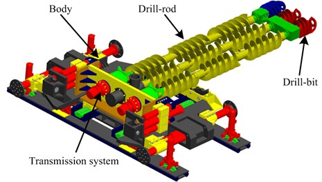
Auger drilling machine is a new type of thin seam coal mining equipment that can realize unmanned, non-supported mining, which will bring a broad application prospects in the future. At present, three bit structure is generally adopted for the multi-drilling mechanism of auger drilling machine to improve the efficiency of coal mining. And the main structure is shown in Fig. 1.
Fig. 1Schematic structure of auger drilling machine
Under the combined effects of the gravity, feeding resistance, resistance torque, damping, impacting force and frictional resistance between drill-rod and coal wall, the multi-drilling mechanism working condition is very harsh, and sometimes the drilling system even deviates from the set direction, which caused by the vibration in drilling. Vibration can reduce the drilling rate, and thereby increase the time and cost of well drilling. It can also cause premature failure of drill bits and other drillstring components. Furthermore, vibrations can interfere with measurement drilling. In order to solve this problem, it is necessary to understand the vibration regularity of multi-drilling mechanism that can predict and control dynamic behavior of drilling mechanism effectively. There is little material or literature about the vibration characteristics for the auger drilling machine is new thin seam mining equipment and the drill-rod is multiple. However, a lot of researches have been carried out about the vibration characteristics of drilling system of other machines similar to auger drill, which can be as a reference for this research.
The bottom hole assembly (BHA) three-dimensional dynamic finite element model was built which considered the inertia force and the friction, and pointed out that the intermittent contact between BHA and wall, dynamic torque and friction have important influence on vibration characteristics [1-2]. Considering the drill-rods and ground as a hole, the influence of boundary conditions on the drill-rods vibration was discussed, where the ground was simplified to mass-spring-damper system, and the bottom-hole was simplified to equivalent spring-damper system [3]. A dynamics model of the pipe-bit-rock interaction system was built to study the effect of drilling pressure, rotating speed, torque and other parameters of the drilling process [4]. A nonlinear model was developed for a drillstring system in deviated well with axially moving motion and axial loading, using the perturbation techniques. Primary and parametric resonance that was investigated for the first time was studied on the nonlinear vibration of the drillstring system [5]. Considering the gyroscopic effect the torsional/bending inertia coupling, and the effect of the gravitational force field, the dynamic model of the drill-rod including the drill collars was established [6-7]. Through analyzing vibration characteristics of the drill-rod under different non-Newtonian flow velocities and densities, a piecewise-smooth model of three degrees of freedom, which exhibits friction-induced stick-slip oscillations, was considered which can be used to describe bit-sticking phenomena [8]. A new method called ‘time history shape function method’ was proposed to study the boundary condition between drill-rod and borehole wall, which proved the method to be accurate and reasonable [9]. Using dynamical analysis tools, the operation recommendations and the detection of safe drilling parameters in a conventional oil well drill-rod was presented, which took into account the fact that the drill-rod length increased as drilling operation and analyzed the reasons of the sliding motion giving rise to self-excited drill-bit stick-slip oscillations and drill-bit sticking phenomena at the bottom-hole assembly [10]. Considering the the self-excited vibrations of rotary drilling systems, a coupling between the axial and torsional modes of vibrations and a state-dependent delay in the governing equations was introduced, and the self-excited response of the drillstring was detected, which indicates that stick-slip vibrations were predicted to occur at natural frequencies [11]. The drill-rod vibrations with differential quadrature method were analyzed, which indicated the method was efficiency and accuracy in dealing with drill-rod vibration problems [12]. A nonlinear model of the drill-rod system in the axial motion and axial load condition was established to study the influence of rotating speed, axial load, unbalance mass and nonlinear fluid forces on the drill-rod vibration characteristics [13]. A finite element model of the drill-rod transverse vibration was built to study the effects of auxiliary support position, drill depth and diameter of borehole on the drill-rod vibration characteristics [14]. Considering the collision conditions of drill-rod and rock, the interacted system coupling dynamics model of multi-drilling mechanism and rock was built and the vibration was acquired under different compression strength rocks and different rotary speeds of drill. The result shown that with the decrease of coal compression strength, the transverse vibration radius, longitudinal vibration frequency and amplitude were all reduced [15]. A method that through adjust the processing parameter to reduce the drill-rod stick-slip vibration and bit bouncing was put forward [16]. The influence of contact conditions between the drill string and the outer shell on the drill-string dynamics, rotation speed and mass imbalance were examined. The findings suggest that small changes in the system rotation speed can have a significant influence on the nature of drill-string motions and provide guidelines for maintaining drill-string motions close to the center of a borehole [17].
The above literature studied the vibration characteristics of single bit multi-drilling mechanism under different boundary conditions, drilling parameters, cutting load etc. However, the vibration characteristics of multi-drilling mechanism under different conditions have not yet been studied, which makes it difficult to predict the drilling vibration, and facilitate the control of the drilling direction. This study is aimed at the dynamic analysis of the drilling system using dynamic modeling and test as a comprehensive approach towards the modeling of a complex system. In this study, for the first time, coupled simulation model of multi-drilling mechanism was established. Then simulation and test research were carried out under different rock hardness, drilling depths and rotating speeds to find out the vibration regularity of multi-drilling mechanism, which will provide references for effectively predicting the vibration of multi-drilling mechanism and improving drilling efficiency.
2. Simulation model
2.1. Basic assumptions
The multi-drilling mechanism is influenced by the gravity, feeding resistance, resistance torque, impacting force and frictional resistance between drill-rod and coal wall in the drilling process. Under these external loads, there are not only longitudinal, transverse and torsional vibrations, but also coupling vibration due to the disturbance phenomenon between three rows of drilling tools and the collision between drill-rod and coal wall. The following hypotheses were put forward for the convenience of analysis [18-19].
1) The cross-section of drilling hole is circular, and the diameter of the hole stays the same.
2) The drill-bit is regarded as a rigid body, while the drill-rod an elastomer.
3) Drill-rod will be subject to constraints of hole wall, and the collision happening between drill-rod and the coal wall is multi-directional and random.
4) Friction resistance between the drill-rod and the broken coal is not considered, as well as the influence of detail structure of multi-drilling mechanism.
5) The transverse vibration is researched through decomposing into and directions on the cross-section. as the horizontal direction, while vertical direction.
2.2. Coupled model
The dynamic model of multi-drilling mechanism was established for the study of multi-drilling mechanism vibration characteristics under different conditions. Research objects are coal hardness, drilling depth and rotary speed, and the corresponding simulation parameters are shown in Table 1. The parameter , known as the coal solid coefficient and fastening coefficient, represents the consistence coefficient of coal, and its value is 1/10 of the limit of the coal uniaxial compressive strength. Different drilling depths corresponds to different number of drill-rod, which followed by 3, 6, 9 and 12. In addition, the multi-drilling mechanism of the feeding speed is 1 m/min. The main dimensions of cutting device are that: diameter of drill bit is 380 mm, length of drill bit is 500 mm, diameter of drill-rod is 380 mm, length of drill-rod is 1268 m. The cutting torque and feed resistance force are shown in Fig. 2 and Fig. 3.
Table 1Research parameter of the multi-drilling mechanism
Parameter | Value | |||
Hardness | 1.43 | 2.07 | 2.88 | 3.6 |
Drilling depth | 4.7 m | 8.5 m | 12.3 m | 16.1 m |
Rotating speed | 40 r/min | 50 r/min | 60 r/min | 70 r/min |
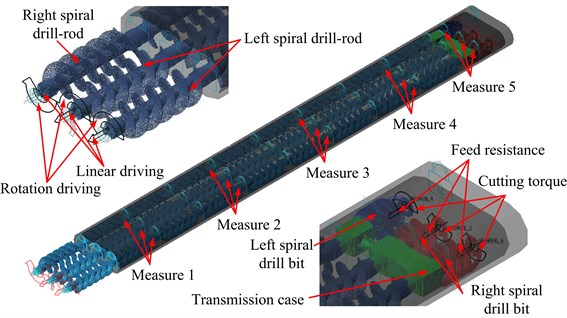
Based on the above assumptions and parameters, the drill-rod is replaced with a flexibility body. The constraints of multi-drilling mechanism and the contacts between the flexible drill-rod and coal wall are set. The rotary driver and line driver are added on the end of drill-rod, and the torque resistance and feeding resistance are added on the drill-bit. The coupled model of multi-drilling mechanism is shown in Fig. 4. Under the different simulation conditions, the coupling dynamic simulation is done. The simulation time is 10 seconds, and the simulation steps are 100.
Fig. 2Cutting torque of difference coal
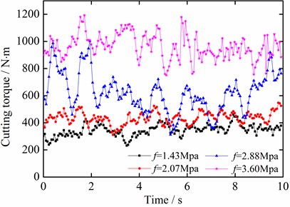
Fig. 3Feed resistance force of difference coal
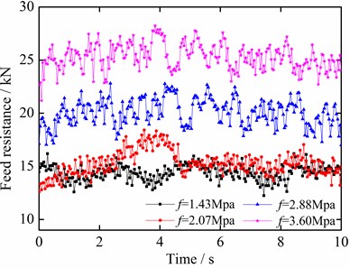
Fig. 4Multi-drilling mechanism coupled model
3. Simulation results analysis
3.1. Vibration characteristics of different coal hardness
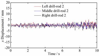
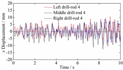
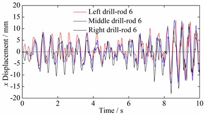
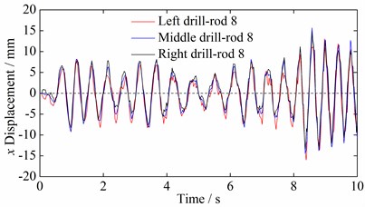
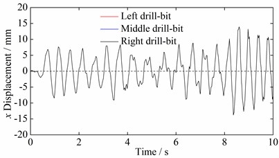
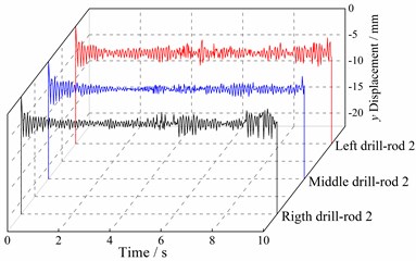
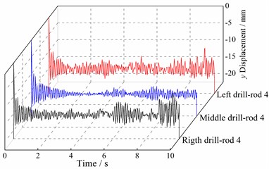
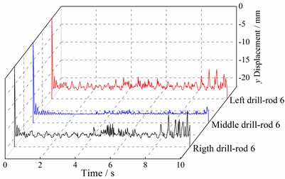
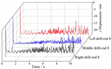
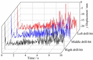
Fig. 5 and Fig. 6 are vibration displacement time domain curves of multi-drilling mechanism of different simulation measuring points (1, 2, 3, 4, and 5) in and directions, respectively. Simulation measuring points 1-5 correspond to the centroids of drill-rod 2, 4, 6, 8 and drill bit.
Fig. 5 shows that the vibration amplitudes of drill-rod in direction near to the drill body section are smaller, and the vibration amplitude and direction are slightly different. The more close the drill-rod to the drill bit, the larger the simulation measuring point vibration amplitude in direction. Meanwhile, the vibration amplitudes and direction tend to be the same. Fig. 6 shows that the vibration amplitudes of drill-rod in direction near to the drill body section are smaller, the more close the drill-rod to the drill bit, the larger the simulation measuring points vibration amplitude in direction.
Due to that the vibration amplitude of simulation measuring point 5 is the maximum, and the vibration condition was the most serious, the vibration displacement at left drill-rod simulation measuring point 5 of multi-drilling mechanism was statistical analyzed. The relationship between vibration displacement of left drill-rod simulation measuring point 5 and coal hardness is shown in Fig. 7. It shows a linear relationship between the statistics of vibration displacement in left drill bit of multi-drilling mechanism and coal hardness. The fluctuations of vibration can be measured by standard deviation. According to the statistics curves, with the increase of coal hardness, vibration magnitude and fluctuation of multi-drilling mechanism increases, and the vibration condition becomes more serious.
Fig. 5Time domain curves of multi-drilling mechanism vibration displacement in x direction
a) Simulation measuring point 1
b) Simulation measuring point 2
c) Simulation measuring point 3
d) Simulation measuring point 4
e) Simulation measuring point 5
3.2. Vibration characteristics of different drilling depths
Fig. 8 shows the movement trajectory of multi-drilling mechanism different simulation measuring points (1, 2, 3, and 4) at the drilling depth of 9 sections drill-rods. Simulation measuring points 1-4 are the centroids of drill-rod 3, 6, 9 and the drill bit.
From Fig. 8, multi-drilling mechanism mainly moves at the lower half of the coal wall hole, and there are frequent collision contacts between the multi-drilling mechanism and the coal wall hole. Thus, its trajectory is quite complex. Comparison of the three rows of drill-rods vibration displacements shows that the vibration displacements on both sides of drilling tool are very close, and the amplitude is larger than that of middle drilling tool. The analysis indicates that the vibration of side drill bit will inevitably make the rest drill bits vibrate to the same direction since the front ends of the multi-drilling mechanism are connected by the box. When the right drill bit vibrates to upper right under the role of gravity and cutting resistance, the middle and left drill bit vibrations also tend to the upper right, and the vibration displacement of right drill bit is maximum and the left is the minimum. Similarly, when the left drill bit vibrates to upper left, the middle and left drill bit vibrations also tend to the upper left. Meanwhile, the vibration displacement of left drill bit is maximum and the right is the minimum. Therefore, the vibration displacements are substantially the same on both sides of the drill bit, but the vibration displacement of middle drill bit is smaller than that of side drill bit.
Fig. 6Time domain curves of multi-drilling mechanism vibration displacement in y direction
a) Simulation measuring point 1
b) Simulation measuring point 2
c) Simulation measuring point 3
d) Simulation measuring point 4
e) Simulation measuring point 5
Fig. 7Relationship between vibration displacement of left drill-rod simulation measuring point 5 and coal hardness
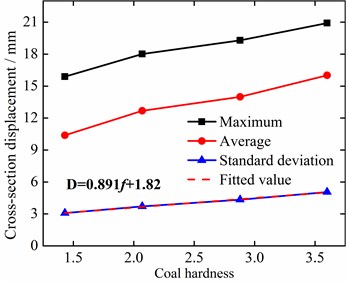
Fig. 9 shows the relationship between the vibration displacement of left drill-rod simulation measuring point 4 and drilling depth. It can be seen from Fig. 9 that the vibration displacement statistics of multi-drilling mechanism left drill bit first decrease then increase with drilling depth, which displays a quadratic polynomial relationship. This indicated that in early drilling, the vibration displacement and fluctuation of multi-drilling mechanism are larger, and the vibrations are violent; with the increase of drilling depth, vibration displacement and fluctuation of multi-drilling mechanism first decrease then increase.
Fig. 8Movement trajectory of multi-drilling mechanism different simulation measuring points at the drilling depth of 9 sections drill-rods

a) Simulation measuring point 1

b) Simulation measuring point 2

c) Simulation measuring point 3

d) Simulation measuring point 4
3.3. Vibration characteristics of different rotating speeds
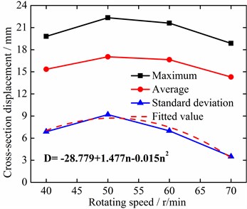
Fig. 10 shows the relationship between the vibration displacement of left drill-rod simulation measuring point 4 and rotating speed. It shows that with the increase of rotating speed, the vibration displacement statistics of multi-drilling mechanism left drill bit first increase then decrease, and have quadratic polynomial relationship with rotating speed. This indicated that when the rotating speed is lower, the vibration displacement and fluctuation of multi-drilling mechanism are smaller, and with the increase of rotating speed, vibration displacement and fluctuation of multi-drilling mechanism first increase then decrease.
Fig. 9Relationship between the vibration displacement of left drill-rod simulation measuring point 4 and drilling depth
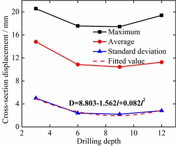
Fig. 10Relationship between the vibration displacement of left drill-rod simulation measuring point 4 and rotating speed
4. Test study
4.1. Test principle
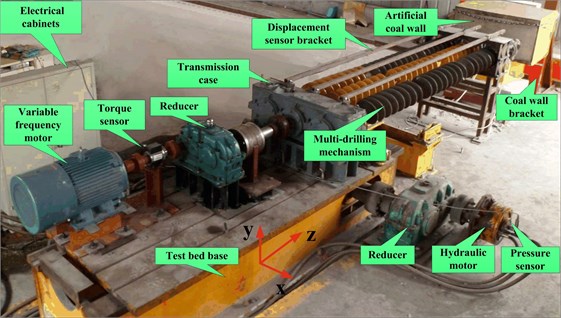
The concrete contents of coal auger multi-drilling mechanism cutting test are coal breaking tests under different coal hardness, drilling depths and rotating speeds basing on the coal cutting test bed [20]; multi-drilling mechanism vibration displacement, cutting torque and feeding resistance were measured through the HZ-891 eddy current displacement sensor, GB-DTS200 digital torque sensor and JNBP-10MPa pressure sensor, respectively. Coal cutting test bed is shown in Fig. 11, in which, the variable frequency motor provides torque for the coal cutting of multi-drilling mechanism through the gear box, and hydraulic motor provides power for the multi-drilling mechanism through rack and pinion mechanism.
Fig. 11Coal cutting test bed
The compressive strengths of test coal wall are 14.3 MPa, 20.7 MPa, 28.8 MPa, 36 MPa; the rotating speeds of multi-drilling mechanism are 40 r/min, 50 r/min, 60 r/min, 70 r/min; the drill-rod sections are 1, 2, 3, and 4. Test measuring points 1, 2 and 3 correspond to the junctions between the first, second and third drill-rod with the drill bit, respectively.
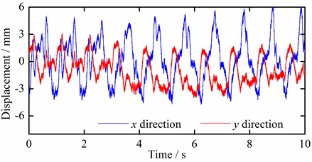
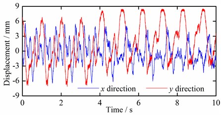
Fig. 12Time domain curves of test measuring point 3 vibration displacements under different conditions
a) Coal hardness (1.43)
b) Drilling depth (3 drill-rods)
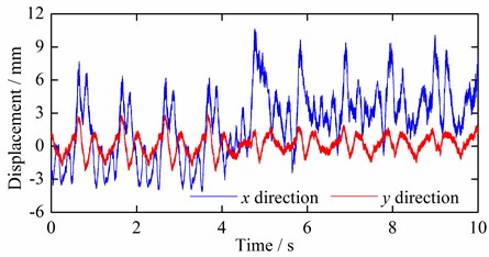
c) Rotating speed (60 r/min)
4.2. Test results
4.2.1. Vibration displacements under different conditions
The displacements of multi-drilling mechanism test measuring point 3 in and directions under different conditions are shown in Fig. 12.
In order to illustrate the vibration laws of multi-drilling mechanism more clearly under different conditions, the cross section displacement is calculated based on the displacement curves in and directions, and the statistical values of test measuring point 3 under different conditions are calculated, which are shown in Fig. 13.
Fig. 12 and Fig. 13 show that with the increase of coal hardness, the vibration displacement statistical values of test measuring point 3 increase gradually, and have linear relationships with coal hardness; with the increase of drilling depth, the vibration displacement statistical values first decrease then increase, and have quadratic polynomial relationship with drilling depth; with the increase of rotating speed, the vibration displacement statistical values first increase then decrease, and have quadratic polynomial relationship with rotating speed. It indicates that the vibration displacement and fluctuation of multi-drilling mechanism increase with the coal hardness, while decrease then increase with the drilling depth, and increase then decrease with the rotating speed. The test results are consistent with simulation results, verifying the correctness of the simulation results.
Fig. 13Statistical values of test measuring point 3 vibration displacements under different conditions
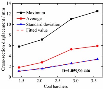
a) Coal hardness
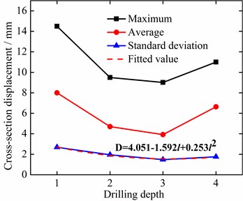
b) Drilling depth
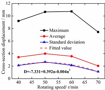
c) Rotating speed
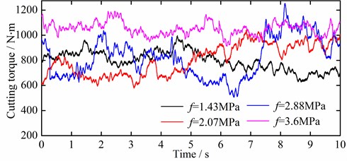
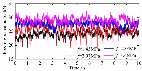
Fig. 14Cutting torque and feeding resistance under different coal hardness
a) Cutting torque
b) Feeding resistance
4.2.2. Cutting loads under different conditions
The cutting torque and feeding resistance of multi-drilling mechanism under different conditions are measured through torque sensor and pressure sensor, and the cutting torque and feeding resistance of multi-drilling mechanism under different coal hardness are shown in Fig. 14.
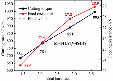
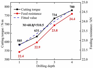
Fig. 15Cutting load averages under different conditions
a) Coal hardness
b) Drilling depth
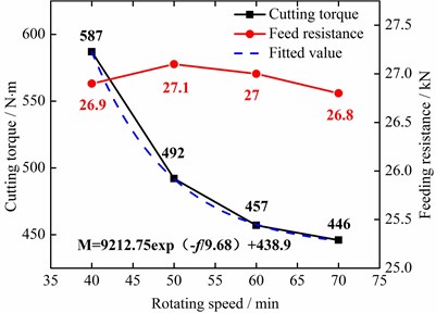
c) Rotating speed
In order to illustrate the variation laws of cutting loads under different conditions, the test load data statistic is conducted out, and the variation curves of cutting load averages under different conditions are obtained, which are shown in Fig. 15.
Fig. 15 shows that the coal hardness and drilling depth have basically linear relation to the cutting torque and feeding resistance of multi-drilling mechanism. As the rotating speed increases, the cutting torque decreases gradually, in exponential relation, but the feeding resistance basically remains consistent. It means that the increases of coal hardness and drilling depth lead to more difficulty for coal cutting. However, the increase of rotating speed can reduce the torque in coal cutting but has little influence on the feeding resistance.
Combining with the tests and simulation results, it indicate that for a certain hardness seam, blindly increasing the drilling depth will not only decrease the drilling efficiency, but also intensity of the vibration and energy loss of multi-drilling mechanism; while under the condition of ensuring coal conveying efficiency, the increase of multi-drilling mechanism rotating speed can effectively reduce vibration and energy loss, and protect the drilling efficiency of shearer.
5. Conclusions
1) A dynamic coupling simulation model of coal auger multi-drilling mechanism was established, and vibrations under different conditions were analyzed. The results show that the vibration displacement magnitude and fluctuation of multi-drilling mechanism increase with coal hardness, while decrease then increase with the drilling depth, and increase then decrease with the rotating speed.
2) The vibration tests of multi-drilling mechanism under different conditions were conducted on the coal cutting test bed, and the variation laws of vibration displacement and cutting load of multi-drilling mechanism were analyzed through measuring the vibration displacement, torque and feeding resistance. The results show that the variation laws of the vibration displacement magnitude and fluctuation of multi-drilling mechanism under different conditions are consistent with simulation results, verifying the correctness of the simulation results. The increases of coal hardness and drilling depth result in more difficulty for coal cutting. The cutting torque decreases with rotating speed, while there is little influence on the feeding resistance.
3) For a certain hardness seam, the blindly increase of drilling depth not only decreases the drilling efficiency, but also intensities the vibration and energy loss of multi-drilling mechanism. While under the condition of ensuring coal conveying efficiency, the increase of multi-drilling mechanism rotating speed can effectively reduce vibration and energy loss, and protect the drilling efficiency of shearer.
References
-
Millheim K. K., Apostal M. C. The effect of bottomhole assembly dynamics on the trajectory of a bit. Journal of Petroleum Technology, Vol. 33, 1981, p. 2323-2338.
-
Macdonald K. A., Bjune J. V. Failure analysis of drillstrings. Engineering Failure Analysis, Vol. 14, Issue 8, 2007, p. 1641-1666.
-
Kovalyshen Y. A simple model of bit whirl for deep drilling applications. Journal of Sound and Vibration, Vol. 332, Issue 24, 2013, p. 6321-6334.
-
Kuang Yuchun, Ma Dekun, Liu Qingyou, Wu zebing Dynamic behavior simulation of the drill string-bit-rock system. Acta Petrolei Sinica, Vol. 22, Issue 3, 2001, p. 81-85.
-
Sahebkar S. M., Ghazavi M. R., Khadem S. E., Ghayesh M. H. Nonlinear vibration analysis of an axially moving drillstring system with time dependent axial load and axial velocity in inclined well. Mechanism and Machine Theory, Vol. 46, 2011, p. 743-760.
-
Khulief Y. A., Al-Naserb H. Finite element dynamic analysis of drillstrings. Finite Elements in Analysis and Design, Vol. 41, 2005, p. 1270-1288.
-
Khulief Y. A., Al-Sulaiman F. A., Bashmal S. Vibration analysis of drillstrings with self-excited stick–slip oscillations. Journal of Sound and Vibration, Vol. 299, 2007, p. 540-558.
-
Navarro-López E. M. An alternative characterization of bit-sticking phenomena in a multi-degree-of-freedom controlled drillstring. Nonlinear Analysis: Real World Applications, Vol. 10, 2009, p. 3162-3174.
-
Zhu Xiaohua, Tong Hua, Liu Qingyou, Feng Linxian Research on the dynamic boundary condition between revolving drill string and borehole wall. China Mechanic Engineering, Vol. 18, Issue 15, 2007, p. 1833-1837, (in Chinese).
-
Navarro-Lopez Eva M., Cortes Domingo Avoiding harmful oscillations in a drillstring through dynamical analysis. Journal of Sound and Vibration, Vol. 307, 2007, p. 152-171.
-
Germay C, Denoël V, Detournay E. Multiple mode analysis of the self-excited vibrations of rotary drilling systems. Journal of Sound and Vibration, Vol. 325, 2009, p. 362-381.
-
Hakimi H., Moradi S. Drillstring vibration analysis using differential quadrature method. Journal of Petroleum Science and Engineering, Vol. 70, 2010, p. 235-242.
-
Sahebkar S. M., Ghazavi M. R., Khadem S. E., Ghayesh M. Nonlinear vibration analysis of an axially moving drillstring system with time dependent axial load and axial velocity in inclined well. Mechanism and Machine Theory, Vol. 46, 2011, p. 743-760.
-
Kong Lingfei, Li Yan, Lv Yanjun, Tang Aofei Dynamic stability domain research on deep hole machining cutting tool system. Journal of China Ordnance, Vol. 5, 2013, p. 611-619, (in Chinese).
-
Liu Songyong, Cui Xinxia, Liu Xiaohui Coupling vibration analysis of auger drilling system. Journal of Vibroengineering, Vol. 15, Issue 3, 2013, p. 1442-1453.
-
Jasem M. Kamel, Ahmet Y. Modeling and analysis of axial and torsional vibrations of drillstrings with drag bits. Society of Petroleum Engineers, 2014, p. 549-560.
-
Liao C. M., Vlajic N., Karki H., Balachandran B. Parametric studies on drill-string motions. International Journal of Mechanical Sciences, Vol. 54, Issue 1, 2012, p. 260-268.
-
Zhu Caichao, Feng Daihui, Lu Bo, Yang Yingxin Nonlinear study on dynamic action of integrated drill string-well rock system. Chinese Journal of Mechanical Engineering, Vol. 43, Issue 5, 2007, p. 145-149, (in Chinese).
-
Su Hua, Wang Guangyuan, Zhang Xuehong Dynamic gap element method for contact-impact problem between slender rod and wall of a round hole. Earthquake Engineering and Engineering Vibration, Vol. 16, Issue 1, 1996, p. 79-86, (in Chinese).
-
Liu Songyong, Du Changlong, Cui Xinxia Research on the cutting force of a pick. Mining Science and Technology, Vol. 19, Issue 4, 2009, p. 514-517.
About this article
This project is supported by National Natural Science Foundation of China (No. 51375478) and Qing Lan Project.
