Abstract
Resource reserves can be effectively controlled through slim borehole horizontal drilling, which can significantly reduce costs and enhance efficiency. Therefore, it has been widely used in petroleum, geothermal, shale gas and water resources exploration. But the large friction between the drilling string and borehole can cause downhole accidents. In this paper, a new method of vibrating drag reduction is proposed, with using turbine to drive the rotary valve to control flow. Axial vibration excitation produced by high-pressure water can greatly reduce the friction. Firstly, a rotary valve mathematical model with flow hydraulic oscillation and vibration is established, whose work characteristics are simulated using numerical methods. And then lab experiments are conducted to verify the design.
1. Introduction
For slim borehole drilling [1], the borehole curvature is often large with long horizontal-section. The wall is exerted by greater pressure and friction, easily causing the drill string buckling [2]. This will result in the weight on bit lose and induce the well accident, seriously affecting the drilling speed. The friction plays a key role in improving the penetration rate, which should be well controlled. The current methods for reducing friction of the horizontal and small diameter wells are primarily consisted of the followings: adding additives to improve the drilling fluid lubricity, controlling the drilling track, and installing anti-friction systems [3]. Generated by high pressure drilling mud axial vibration force of the hydraulic oscillator, the static friction can be converted to kinetic friction, increasing the dynamic stiffness of the tool [4], which is regarded as the best drag reduction mode and has great prospective.
Since the 1990s, many international oil companies are committed to study hydraulic oscillator, which has been commercialized application as a representative is the Axial-oscillation Generator Tool (AGT) [5], which was developed by National Oilwell Varco (NOV), and originally used in coiled tubing drilling. However, due to the better vanquishing effect [6], the soft longitudinal reciprocating vibration can be produced at the bottom of the column [7], reducing the friction between the drilling string, and making the borehole wall during drilling weight on bit (WOB) effective delivery. It can also reduce the torque gradually, which allows it tobe used in highly deviated wells, and multi-branch horizontal well drilling [8]. In 2001, Rasheed W. et al., In a well in the North Sea for Andergauge Ltd introduced downhole vibration tool (Agitator) on-site applications, and the hydraulic oscillator was first put into use in China’s domestic Su 36-8-18H wells where the drilled rate was increased by 30 %-40 % [9]. In 2012, Xin sha well 21-28 [10], Reach well Zhang 29-38L wells and horizontal wells in Sichuan and Chongqing also used this tool, achieving good effects. In the same year, Daqing Drilling Engineering Company developed a new hydraulic oscillator, the power section and the valve shaft portion with a structure instead of the blade achieving power and functionality with streaming capabilities [11].
The paper [12] compares a number of field runs with and without an AGT and quantifying the actual downhole accelerations caused by adding the oscillation system to the drill string. The results show that the addition of an effective axial oscillation tool positively influences drilling performance while maintaining compatibility with all drill string components. The paper [13] focuses on expansion of the tool application with both conventional rotary and rotary steerable BHA's. Significant improvements in drilling performance are revealed when combining AGT and RSS. In the paper [14], the reach extension in the field trials with modeling predictions is compared by using tool output measured via a downhole force gauge. Zhang Hui [15], and Wang Guohua [16] designed a disc spring type hydraulic oscillator, and accomplished the laboratory and field test [17]. The paper [18] reviews the benefits and drawbacks of Axial Oscillation Tools and Lateral Vibration Tools. The research concludes that axial oscillation tools provide significantly more effective friction reduction. The paper [19] presents the benefits of utilizing the axial oscillation tool in conjunction with standard RSS drive systems in directional drilling applications. This provides a significant reduction in stick slip vibration levels and more stable drilling operation in all modes of drilling. Steve Jones [20] describes the operation and field-test results from a new axial oscillation tool, which uses a mud valve to generate pressure pulses in the string. These pressure pulses are magnified using a specifically designed stroke tool referred to as an amplifier. The mud valve is driven with a short power section from a Positive Displacement Motor (PDM). Experimental studies have been carried out on the valve disc parameters, such as, oscillation frequency,pressure drop,flow rate and the valve disk, the effects on the hydraulic oscillator performance have been studied by Luo Chaodong [21].
In summary, based on a variety of hydraulic oscillator field applications, the current problems are mainly in the following aspects: (1) Pressure drop loss is generally too large, leading to the local head loss significantly. Consequently, the pressure of the impact crushing caused by the drilling fluid will be reduced, which results in the rock drilling capacity decline. (2) The study unnatural frequency of the drill string and hydraulic vibrator is not adequate. The hydraulic oscillator or the hydraulic parameters should be placed properly to avoid resonance, reducing the damage of the MWD downhole and other precision instruments. (3) The research on hydraulic oscillator mechanism is short, so that the relevant hydraulic and structural parameters selection is not accurate. (4) Due to the presence rubber parts, the PDM cannot be used in high temperature drilling. (5) The materials used in hydraulic oscillator needs to be further optimized to reduce water erosion and increase the component life.
In this paper, we firstly propose a basic structure of the turbine-driven hydraulic oscillator whose flow is controlled by valve. A friction model, circulation valve vibration model, and drag reduction model were established by the use of dynamics, hydraulics and tribology theory. Based on the results made by numerical simulation analysis, lab experiments were conducted to verify whether its work mechanism is right. The influences of the structural parameters and hydraulic parameters on the hydraulic oscillator were researched out, which helps to determine the optimum vibration frequency, lying a good foundation for further research and application of drag reduction method.
2. Model of vibrating drag reduction
2.1. Model of friction
For the axial hydraulic oscillation, it can transform the coefficient of static friction to the kinetic, and by periodically lowering the drill string and the borehole wall positive pressure, the frictional resistance between the drilling string and the borehole wall can be reduced. According to the basic principles of tribology, the static friction and dynamic friction are expressed as:
In general, . The drill string can be stick due to the large friction. When it is performed as the static one, the axial vibration can be converted into the dynamic one to reduce the friction.
Fig. 1The change of the instantaneous velocity with friction
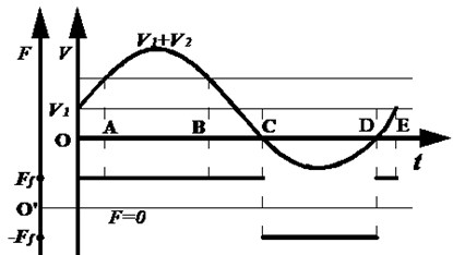
When the drill string vibrates in axial, the vibration speed will super impose on the drilling speed. Fig. 1 plots the change of the instantaneous velocity at one point of the drill string with friction and time. Studies have shown that the velocity varies by sine law. Let vibration period be , and the instantaneous velocity of a particle after being superimposed can be expressed as:
In Fig. 1, OC represents , CD represents , and DE represents . Then the vibration time in the positive direction within one period of time is:
In the negative, vibration time is:
Let the frictions be positive when the vibration occurs in the positive direction. Therefore, within a period of oscillation, the friction can be partly offset. So, an average friction force can be expressed as in Eq. (5), which is significantly less than the frictional force without the vibration friction:
2.2. Model of rotary valve
Fig. 2 plots the rotary valve model with hydraulic flow. - represent the annulus area of the spool connected parts, represented by where the pressure and flow rate with the corresponding positions are and (where 1, 2, 3, 4, 5, 6) respectively.
Fig. 2Rotary valve structure model
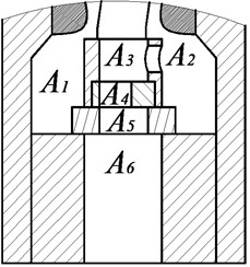
Let the local head loss through every flow area be . According to the law of energy conservation, the energy loss is:
The total loss and the local head loss of the fluid from the rotation valve to the static valve can be expressed respectively as:
According to the Bernoulli’s equation, the corresponding pressure at each point can be calculated by Eq. (8):
The force of the static valve is from the rotary valve outlet pressure difference, water hammer drilling fluid force and the axial force from the motor rotor, which is calculated by Eq. (9):
According to the force analysis, the pressure difference between inlet and outlet And can be calculated by Eq. (10):
The water hammer force produced by drilling fluid can be calculated by Eq. (11):
The axial force from the motor rotor is calculated by Eq. (12):
2.3. Flow area calculation model
The water hammer force is affected by the flow area of rotary valve and its structure. It uses the structure of eccentric hole in rotary valve, as shown in Fig. 3(a) and Fig. 3(b) respectively. Two ultimate states during rotation of the rotary valve and the valve with the static flow area of the shaded figure are the drilling fluid flow area in Fig. 3.
Fig. 3The limit position of the rotation valve
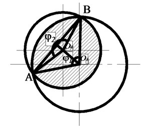
a) Max area
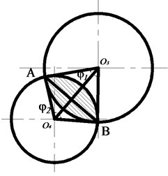
b) Min area
During the rotation, due to the relative position of the eccentric of radius 3 and 4, two circular flow areas have always been in change. Set is the center of the static valve hole, so the maximum flow area and minimum flow area can be calculated by Eq. (13):
If are much larger than , the two circles may not intersect when in a certain period of time. When circle is included in the inner circle of , the flow area can be calculated by Eq. (14):
If the center of circle is coincident with the center of the stator, the distance from the circle to circle is calculated by Eq. (15):
The intersecting chord of can be calculated by Eq. (16):
The central angle of and to arc CD are calculated by Eq. (17):
So, when , Flow area can be expressed as Eq. (18):
When , Flow area of drilling mud can be calculated by above-mentioned method, while the results must get by exchanging the r1 and r2 in Eq. (18).
2.4. Model of vibration drag reduction
Fig. 4 plots the model to simulate the vibration of the horizontal section. The left end is fixed, where the phenomenon of sticking is investigated under pressure. The right is exerted by the effect of hydraulic oscillator excitation, where the non-excited state and excited state are investigated respectively.
Resonance for the house of hydraulic vibrator oscillation frequency of the natural frequency of the drill string, must be analyzed on the natural vibration frequency of drill. Let and the total length of the drill string be fixed at one end, used to indicate displacement of a point on the drill string. The drill string is assumed due to the homogeneous elastomer, then the lines of constant density , cross-sectional area of the drill string , modulus of elasticity of the drill string material is .
Fig. 4Axial vibration model of drilling string
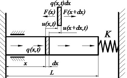
For periodic rotation, the total length of the drill string is constant. The vibration displacement amount changes over time can be considered as a harmonic function of time. To the drill string under tension, for example, by taking a short length of the analysis, you can get the drill string vibration equation is calculated by Eq. (19):
The natural oscillation frequency of the drill string is , and . Assuming fixed at one end of the drill string, and the other end is elastically supported, which supports that stiffness coefficient is , the following boundary conditions:
According to Eq. (19), the boundary condition , and substitute it into Eq. (20), we can get the formulate:
When the other end of the drill string is free to move, 0 and 0, whose solution is:
When the other end of the drill string is fixed, and , whose solution is:
Let the damping ration is . The natural frequency can be expressed as Eq. (24):
According to equations from Eqs. (22)-(24) and the conditions of the string itself, the natural frequency are related to and . As the drilling goes on, the value of and will also increase, which can result in the decrease of the natural frequency. Assume that the damping ratio is always the same. According to the conclusions obtained, the hydraulic oscillator should avoid the resonance frequencies within the range of different depth.
The represents the load distribution at point of when hydraulic oscillator’s works as is shown in Fig. 4. When the vibration excitation increases, the motion equation of the free vibration can be expressed as Eq. (25):
The general solution of Eq. (25) can be expressed as:
The vibration frequency after excitation is with its motion function . Substitute Eq. (26) into Eq. (25), we can get:
After one hydraulic oscillator of the model shown in Fig. 4 is added at the free end, the excitation force can be since the water generated by the oscillator is a sine wave excitation harmonic excitation. Based on Eq. (27), we can get:
After integrating the right part of Eq. (28), it can be changed into:
According to the Duhamel’s principle, we can get the solution of Eq. (29) as:
Substitute the solution on of Eq. (29) into Eq. (26), we can get the steady state response as:
According to the model calculated above, it is shown that the vibration displacement is closely related to the length of the drill string. When the total length of the borehole is given, the closer of the position of hydraulic oscillator to the bit, the larger the length is, which means the larger of the vibration amplitude. This can effectively overcome the friction, till up to the ground. The vibration can be gradually weakened and the energy can be absorbed by the drill string.
Let the string drilling speed per unit time is , and the instantaneous displacement of one place can be expressed as:
Let the drilling direction be positive when it agrees with the direction of and the displacementis positive when the friction is positive. When the reverse displacement caused by vibration is greater than , the negative frictional resistance will be produced, resulting in a less total friction.
3. Methodology
3.1. Simulation model parameters
According to the aforementioned mathematical model, the software AMESet is used to establish the valve element model. Set the port variables and parameters control valve. The simulation process can be expressed as: the drilling fluid flows from the vibration input into the model system, then enters the valve model. The control valve model is driven by motor to cause the flow area change. The changes feedback to the vibration model simultaneously. The vibration of the massive model can be achieved through the area difference between the upper and lower ends of the valve piston. The basic parameters of the simulation are shown in Table 1.
Table 1The basic simulation parameters
Items | Value | Unit |
Displacement of pump | 360 | cc/rev |
Ration speed of driven motor | 1000 | rev/min |
Stiffness coefficient of spring | 3100 | N/m |
Initial speed of mass | 0 | m/s |
Mass | 1000 | kg |
Static friction coefficient | 0.15 | null |
Dynamic friction coefficient | 0.12 | null |
Angle of rotation valve | 190 | degree |
Diameter of rotation | 40 | mm |
Rotation speed of valve | 600 | rev/min |
3.2. Experimental method
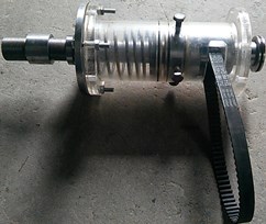
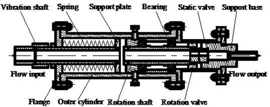
To verify the above mathematical model, in this paper, an independent design of the experimental apparatus is shown in Fig. 5. Both ends of the device are pressure transducer interface, with pump and water tank connected, respectively. The transparent glass-cylinder is used in the vibration device in order to observe the internal vibration process. The input shaft by the motor speed and torque through timing belt to simulate transient rotation characteristics and transient pressure and flow characteristics. Valve of a structure using an eccentric hole through the mud pump input flow constant pressure.
Fig. 5Experimental device
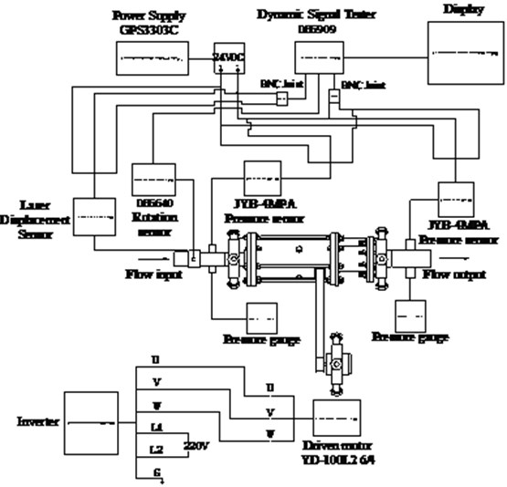
Experimental parameters that need to be tested include spring compression displacement, the amplitude of vibration, frequency of vibration, import and export pressure, flow of drilling pump, and rotation speed. JYB-4 MPa pressure transmitter is used to test the stress. CD33-120NV laser displacement sensor is used to collect the vibration displacement and vibration frequency. DH5909 handheld dynamic signal tester is used to acquire data, which is mainly suitable for IEPE sensors. In this paper, non-IEPE sensor is the mere tester to be used, so BNC connector is selected correspondingly. The experimental program is shown in Fig. 6.
Fig. 6Experimental program
4. Result and discussions
4.1. Simulation results
4.1.1. Vibration amplitude variation
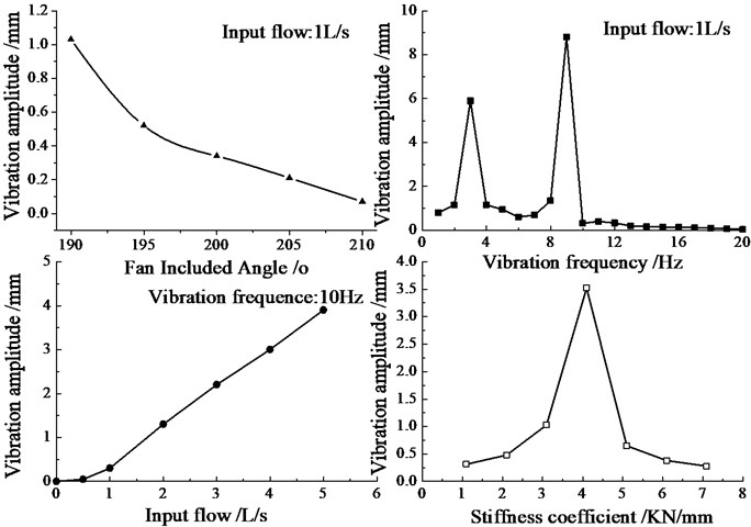
Fan included angle, valve orifice area flow area, vibration frequency, input flow, and equivalent stiffness have great influence on hydraulic oscillation amplitude. Through simulation, the influence of these factors can be obtained and shown in Fig. 7. The opening angle increases as the flow area increases, causing the amplitude decrease slowly at first and then rapidly to the end. The resonance occurs when the frequency is between 3 Hz and 9 Hz; the amplitude will increase linearly; when the equivalent stiffness coefficient is less than 4.1 KN/mm, the amplitude will increase, while when the stiffness coefficient is greater than 4.1 KN/mm, the amplitude will decrease, where there is a maximum.
Fig. 7Vibration amplitude variation
4.1.2. Vibration force variation
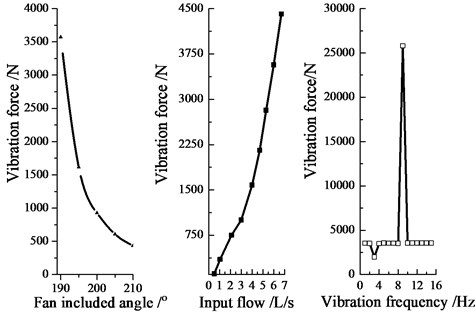
Hydraulic oscillation exciting force is decided by flow area of rotary valve, drilling fluid flow, and vibration frequency. Through simulation, the outcomes can be obtained as is shown in Fig. 8. The exciting force decrease with the flow area increases, with the reduced speed gradually slowing. Exciting force and amplitude vary with the flow are the same as a linear growth. Under the same condition, it can be seen that the amplitude indirectly reflects the exciting force. The influence of vibration frequency is little on the exciting force and amplitude. Fig. 8 shows that abnormal enlarged vibration forces appear at 3 Hz and 10 Hz, which means that the resonance occurs. Therefore, this area should be avoided. Based on the above analysis, the smaller flow area is, the greater the flow and the centrifugal force are.
Fig. 8Vibration force variation graph
4.2. Experiment results
4.2.1. Vibration amplitude and force variation
During the experiment, the vibration shaft will vibrate stable after it compresses near the equilibrium. According to the corresponding amount of compression spring, the exciting force can be calculated under this condition. Therefore, spring compression directly reflects the exciting force. Let the rotational speed be 300 rpm, 600 rpm and 900 rpm, with the flow being 0.5 L/min, 1 L/min and 1.6 L/min. The changing laws of the vibration amplitude and excitation force are examined through the experimental device, which will be compared with the simulation results.
Fig. 9 plots the displacement and vibration amplitude when the rotary speed is 600 rpm, that is, when the vibration frequency of 10 Hz, and flow rates are 1 L/s and 1.6 L/s respectively. When the rotational speed is 600 rpm with the flow rate of 1 L/s, the vibration amplitude generated by the oscillator is about 0.3 mm. When the flow rate is 1.6 L/s, the vibration amplitude is about 1.4 mm. With increasing flow, the spring compression becomes larger, reflecting the exciting force becomes larger. The experimental results well agree with the simulation results as shown in Fig. 8.
Fig. 9Vibration amplitude variation graph with flow
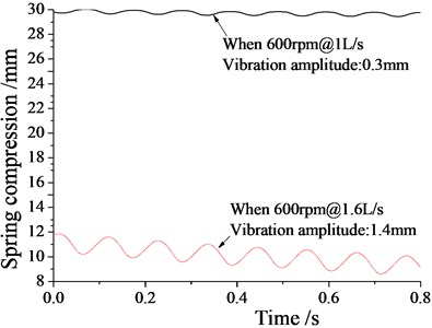
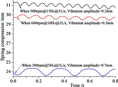
Fig. 10 shows vibration amplitude and displacement when theoretical speed is 300 rpm, 600 rpm and 900 rpm, and the vibration frequencies are 15 Hz, 10 Hz and 5 Hz with the same flow rate 1 L/s. The stable amplitude of the hydraulic oscillator are 0.7 mm, 0.3 mm and 0.2 mm, in line with the aforementioned simulation results. With increasing speed and vibration frequency, the vibration amplitude variation becomes smaller, but with gradual increase of the compression spring, reflecting that the exciting force also becomes larger.
Fig. 10Vibration amplitude variation graph with rotation speed
4.2.2. Pressure drop loss variation
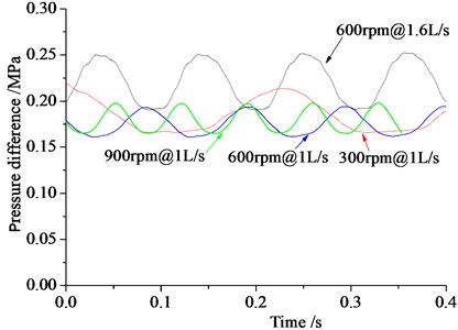
Fig. 11 shows the law of pressure drop with flow and speed. It can be seen from the figure that with a valve at the same speed, the pressure drop at the valve port becomes larger as the flow increases. When the flow rate is the same, as the speed increases, the valve opening pressure drop will slightly reduce. But the overall pressure drop is small, which is between 0.16-0.25 MPa. The results indicate that the design effectively reduces stress loss, helping to improve the drilling efficiency.
Fig. 11Pressure drop loss variation graph
5. Conclusions
Based on the rotary valve with flow, the hydraulic vibration drag reduction mechanism is studied through theoretical analysis and simulation. To verify the simulation results, an independent experimental device is designed. In the paper, we can get the following conclusions:
1. The natural frequency of the oscillation is related to the drill string mass and the total length of the drill string . With the increasing of borehole length, mass and length will increase, but with the decrease of the natural frequency. When the damping ratio is assumed under the same condition, a hydraulic oscillator with higher vibration frequency shall be selected when the horizontal section is longer.
2. The vibration amplitude and exciting force of drill string can be adjusted by the valve orifice area, vibration frequency, input flow, and other parameters. The exciting force and vibration amplitudes both become smaller as the area becomes larger. With the increase of the rotational speed of the rotary valve, the vibration amplitude becomes smaller, but the exciting force becomes larger. And with the increase of the flow rate, the amount of compression of the spring becomes larger, reflecting the exciting force can also become larger.
3. The hydraulic oscillator should be used at a frequency that is different from the resonant one of the drill string to avoid the damage to the drill string. The best frequency range is determined as 10-15 Hz when using the Ø89 hydraulic oscillators.
4. Based on the proposed flow rotary valve, the pressure drops of the hydraulic oscillators only 0.16-0.25 MPa, far lower than the one used currently. This can be used to effectively reduce the pressure loss, helping improve the drilling efficiency and proving the correctness of the program.
References
-
Cohen J. H., Leitko C. E., Long R. C. Slimhole drilling system doubles penetration rates. Oil and Gas Journal, Vol. 98, Issue 15, 2000, p. 67-69.
-
Gao Guohua, Miska Stefan Effects of friction on post-buckling behavior and axial load transfer in a horizontal well. SPE Journal, Vol. 15, Issue 4, 2010, p. 1110-1124.
-
Zhu Hai-yan, Liu Qing-You, Wang Teng Reducing the bottom-hole differential pressure by vortex and hydraulic jet methods. Journal of Vibroengineering, Vol. 16, Issue 5, 2014, p. 2224-2249.
-
Newman K. R. Vibration and rotation considerations in extending coiled tubing reach. SPE/ICoTA Coiled Tubing and Well Intervention Conference and Exhibition, The Woodlands, Texas, USA, 2007.
-
Bybee, Karen New downhole tool extends coiled-tubing reach. Journal of Petroleum Technology, Vol. 52, Issue 6, 2000, p. 32-33.
-
Rasheed W. Extending the reach and capability of non-rotating BHAs by reducing axial friction. SPE/ICOTA Coiled Tubing Roundtable, Houston, Texas, 2001.
-
Falodun S., Kellas M., Ehrunmwunsee K. Optimal horizontal wellbore placement using new drilling technology in the Niger Delta-Bonga field case study. 18th World Petroleum Congress, Johannesburg, South Africa, 2005.
-
Maidla Eric, Haci Marc Understanding torque: the key to slide-drilling directional wells. IADC/SPE Drilling Conference, Dallas, Texas, 2004.
-
Shi Chongdong, Dang Kejun, Zhang Jun, Zhu Caihua, Gao Long, Yang Bixue Application of the hydraulic oscillator in Well 36-8-18H of the Sulige block. China Petroleum Machinery, Vol. 40, Issue 3, 2012, p. 35-38.
-
Xu Hao, Niu Hongbo, Tang Honglin, Zhang Xiaoming Application of hydraulic oscillators to the development of well Xinsha 21-28H in the Xinchang gas field. Western Sichuan Basin. Natural Gas Industry, Vol. 33, Issue 3, 2013, p. 64-67.
-
Li Bo, Wang Yuxi, Sun Zexin, Liu Guo-heng Development and Application of Ø178 Hydro-oscillator. Oil Field Equipment, Vol. 42, Issue 8, 2013, p. 55-57.
-
McCarthy John Patrick, Stanes Brett, Rebellon Jorge Eliecer, Leuenberger Greg, Clark Kevin, Kollker Colin, Grabski Lauren A step change in drilling efficiency: quantifying the effects of adding an axial oscillation tool within challenging wellbore environments. SPE/IADC Drilling Conference and Exhibition, Amsterdam, The Netherlands, 2009.
-
Alali Aref, Barton Steven Paul Unique axial oscillation tool enhances performance of directional tools in extended reach applications. Brasil Offshore, Macaé, Brazil, 2011.
-
Wicks Nathan, Pabon Jahir Alfonso, Zheng Andrew S. Modeling and field trials of the effective tractoring force of axial vibration tools. SPE Deepwater Drilling and Completions Conference, 2014.
-
Zhang Hui, Yu Wen-tao, Chen Zhong-shuai, Cai Wen-jun Development of hydropluse axial-oscillation friction-reduce tool. Oil Field Equipment, Vol. 43, Issue 7, 2014, p. 73-76.
-
Wang Guohua, Chen Zhengmao, Qin Dawei, Dong Xuecheng, Li Yuanyuan Research on improving ROP by hydraulic pulse vibrating drilling tool. Drilling and Production Technology, Vol. 38, Issue 5, 2015, p. 25-27.
-
Zhang Hui, Wu Zhonghua, Cai Wenjun Development and field testing of hydraulic oscillator. China Petroleum Machinery, Vol. 42, Issue 6, 2014, p. 12-15.
-
Gee R., Hanley C., Hussain R., Canuel L., Martinez J. Axial oscillation tools vs. lateral vibration tools for friction reduction – what’s the best way to shake the pipe. SPE/IADC Drilling Conference and Exhibition, London, England, UK, 2015.
-
Altamimi Ibrahim M., Mokrani Samir, Zulkaf Ahmed H. Axial oscillation tool significantly mitigates the vibration level and enhances drilling performance in conjunction with standard rss systems. Abu Dhabi International Petroleum Exhibition and Conference, 2015.
-
Jones Steve, Feddema Chad, Sugiura Junichi, Lightey Jeff A new friction reduction tool with axial oscillation increases drilling performance: field-testing with multiple vibration sensors in one drill string. IADC/SPE Drilling Conference and Exhibition, Fort Worth, Texas, USA, 2016.
-
Luo Chaodong, Yan Biao, Xia Chengyu, et al. Experimental study on the factors impacting the performance of the hydraulic oscillator. China Petroleum Machinery, Vol. 44, Issue 1, 2016, p. 25-28.
About this article

This work is supported by National Natural Science Foundation of China (No. 41572360, 41672366), the National Key Technology Support Program (No. 2015BAD20B02) and the Fundamental Research Funds for the Central Universities (No. 292015061). Meanwhile, great thanks also go to former researchers for their excellent works, which give great help for our academic study.
Yu Wang and Bairu Xia establish the mathematics model. Yu Wang and Zhiqiao Wang conceived and designed the experiments, and they also wrote the paper. Zhiqiao Wang performed the experiments. Baolin Liu analyzed the data. Jun Zou contributed simulation results.
