Abstract
In this paper a nonlinear dynamic model for drill string in inclined well drilling is developed. Effects of drilling mud flow rate, weight on bit, angular velocity along with viscous damping on stability and vibration of the drill string are studied. Findings indicate the nonlinear effects are significant on the results. The effects of drilling mud flow rate and weight on bit on the natural frequencies and time responses are evaluated. Enhancement of drilling mud flow rate results in decreasing of natural frequencies and vibrational amplitude, while increasing the weight on bit, leads to decrease of the natural frequencies and increase the vibrational amplitude.
1. Introduction
Investigation of vibrations in drill string like every other rotary machine is very important. Impact and friction at the borehole/drill string, wall contact, stick-slip, initial curvature in the drill collar section and the deviation angle of the borehole are the main causes of drill string vibrations.
Drill string vibrations are generally complex because all axial, lateral and torsional vibrations are present and coupled linearly and nonlinearly. Dunayevsky et al. [1] studied modal characteristics of the drill string using finite element method to analyze instability. They considered linear coupling between the axial and transverse vibrations. Jansen [2, 3] studied the transverse vibrations of drill string caused by whirling considering contacts with the wellbore wall. In the next work, he designed a control system for reduction of torsional vibration using torsional pendulum model. He did not consider the effects of axial force. Yigit and Christoforou [4-6] worked on dynamic models of nonrotating and rotating drillstring. They studied coupled vibrations between axial-transverse and torsional-transverse separately.
Khulief and Al-Naser [7] used Lagrangian approach to formulate the finite element model of a rotating drill string considering the effect of the neutral point position. Apostal et al. [8] developed a three dimensional finite element model to study the forced frequency and harmonic response of a non-rotating BHA. Berlioz et al. [9] used finite element method with the rotor dynamics theory to formulate dynamic model for the drill string. Many researches were carried out regarding bending vibration and stability [10, 11], modeling of mud [12, 13] and modeling of rotating beam and its dynamics [14, 15].
In modeling the drilling mud, Paidoussis [12, 13] studied dynamics of a hanging tubular cantilever conveying fluid downwards in inner of the cantilever and upwards in the outer annular region contained by the cantilever and a rigid cylindrical channel.
The main purpose of this paper is to develop a nonlinear model and investigation of time response for a drill string system dynamics in an inclined well with considering mud flow rate by FEM. In this article for the first time nonlinear formulation of directional drilling dynamics is developed and effects of mud flow rate, WOB and angular velocity are considered simultaneously on drill string stability and time response.
2. Material and method
2.1. General method of solution
First kinetic and potential energies of an element of drill string are derived. In these equations the effect of geometrical shortening, which couples axial and lateral vibration, is considered and nonlinear coupling terms are retained. Because natural frequencies of axial vibrations are several orders of magnitude higher than those of the torsional vibrations [14], torsional vibrations are not considered. The motion equation of the drill string system is derived through Hamilton's principle. To find static stability first we have to find equilibrium points of the system. This would be done by taking the first order derivative of the potential energy. And after that to find the stability of equilibrium points, sign of the second order derivative should be examined.
In this paper the eccentricity of drill string is omitted and the system is assumed to be balanced. Also helical buckling is neglected and contact between the drill string and the wellbore is assumed to be only in the stabilizer’s position and the clearances between stabilizers and borehole wall are neglected. In deviated hole, drill string is supposed as a straight beam and the effect of well curvature is not being included. Numerical solutions obtained in this study are compared with the available experimental data to validate the theoretical results.
2.2. Equation of motion
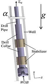
Each part of drill string (pipe or collar) is assumed to be hollow solid cylinder with uniform cross section (Fig. 1). Gyroscopic moments due to rotation of the drill string and transverse vibration are included through external virtual work terms.
Fig. 1Presentation of general model of drill string
2.3. Kinetic and potential energies
Kinetic and potential energies of a rotating beam element with constant angular velocity can be written as [15]:
where is the mass density of the drill string, is the length of the element whether in drill pipe or drill collar, is the global coordinate of the first node of element, is the element cross-sectional area, are components of mass center velocity of an element and denotes a partial derivatives with respect to . The potential energy of an element of drill string is expressed as below. Note that is the deviation angle of the borehole:
From Eq. (2) coupling between transverse and axial deformations is evident. Using finite element method to convert non-linear integral of energies to non-linear scalar ones, and finding the minimum path of variation by the equilibrium position of Lagrangian, equations of motion can be written. To model lateral and axial vibrations, beam’s and bar’s shape functions are used.
2.4. Virtual work
The virtual work due to gyroscopic moments can be written as [5]:
For the virtual work done by drilling mud, all of hydrodynamic forces on drill string which are in-viscid, viscid and frictional forces should be calculated. These forces are formulated in [12, 13]. By evaluation the works done by external forces associated to each element, the appropriate matrixes would be assembled and the final form of works done by external forces would be achieved.
2.5. Assembled potential and kinetic energy
Using Lagrangian principle by combination of kinetic and potential energy with works done by external forces, equations of motion can be developed. Stabilizers are assumed to limit any displacement in lateral directions and prevent drill collar from bending in or directions. To apply boundary conditions, the whole drill string is supposed to be a simply supported rotor. The equations of motion can now be derived by using Lagrangian method. In order to find the stability condition of the drillstring, it is needed to find the equilibrium position of the string, dropping time dependent terms from equations of motion.
2.6. Investigation of equilibrium regions
To find the stability of these positions, the second order derivative of the system’s Lagrangian should be examined. If the matrix of the second order derivatives of the system’s Lagrangian is positive definite, the equilibrium position is stable; otherwise it is unstable.
3. Results and discussions
3.1. Results
This simulation is based on Khulief’s drillstring model [7] in which inclination of the string is not included. The drill string configuration is listed in Table 1.
In drilling process, the angular velocity is about 100-300 rpm [6], consequently effects of angular velocity can be neglected for static stability analyses. In all figures, height of the neutral point which causes buckling is known as the critical height of neutral point and represented by (H).
In Fig. 2 effects of deviation angle of the well on drill strings stability is presented. Different flow rates and angular velocities are compared. It is shown increasing mud flow rate and angular velocity of drill string will decrease the ultimate of weight on bit for stable drilling.
Table 1Drill string configuration used by Khulief [7] (aside from lengths)
Drill pipe specification | Material specification | ||
Length (m) | 1000 | Drill string density kg/m3 | 7850 |
Outer diameter (mm) | 127 | Modulus of elasticity GPa | 210 |
Inner diameter (mm) | 95 | Drilling mud density kg/m3 | 1500 |
Drill collar specification | General specification | ||
Length (m) | 200 | Borehole diameter (mm) | 300 |
Outer Diameter (mm) | 228 | Gravity acceleration m/s2 | 9.81 |
Inner Diameter (mm) | 76 | Deviation angle rad | 0.0524 |
Fig. 2Stability threshold of drill string with parameters according to Table 1 and length which are 20 m for drill pipe and 100 m for drill collar with one stabilizer at xstab= 70 m from the top
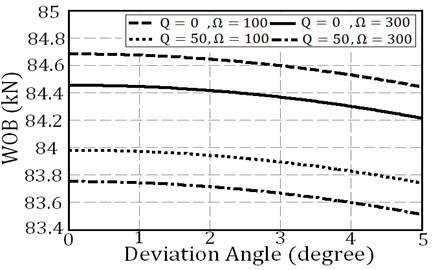
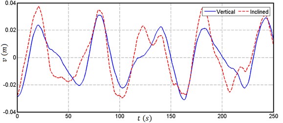
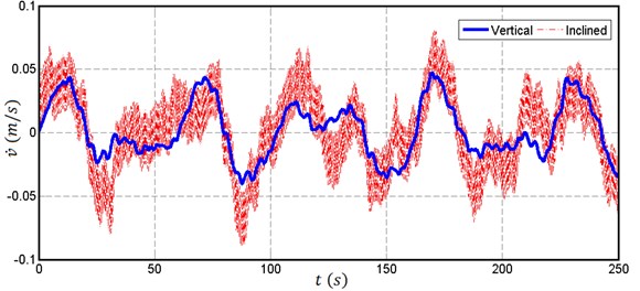
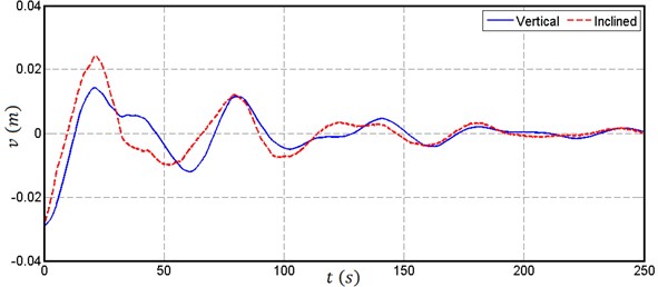
Fig. 3Comparing a) amplitude and b) velocity of vibration in vertical and inclined drill string with deviation angle 3 degree in response to H=10+10sin(10πt/3) with Ω= 100 rpm and Q=0
a)
b)
Time response of a drill string in deviated well is compared to vertical well. To discuss the nonlinear response of drill string in deviated wells, time responses of vibration in deviated and vertical drilling are compared in Fig. 3. In this comparison the mud flow rate is neglected so that the effects of deviation are easier to follow. As the Fig. 3 indicates, damping of system is low due to static mud around the drill string and Fig. 4 shows that how mud flow rate would damped the vibration of drill string either in vertical or deviated drilling.
Fig. 4Comparing a) amplitude and b) velocity of vibration in vertical and inclined drill string with deviation angle 3 degree in response to H=10+10sin(10πt/3) with Ω= 100 rpm and Q= 50 lit/s
a)
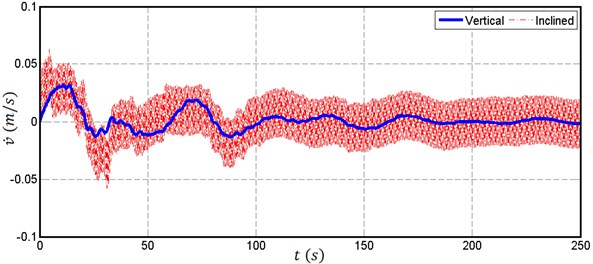
b)
Also in deviated drilling, natural frequency of drill string would decrease, and amplitude of lateral vibration would increase in comparison to vertical drilling. This behavior is the result decrease of WOB.
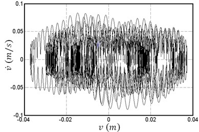
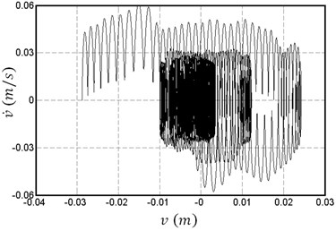
In Fig. 5 velocity variation versus lateral deflection with and without mud flow rate in deviated and vertical drillings are compared. It is shown damping effect of mud flow rate cause the drill string to vibrate around its stable position as time passes. In vertical drilling, drill string vibrates in an elliptical way around its stable point, however in deviated drilling not only it vibrates around its stable center, but also it vibrates continuously around its temporary stable center with very low frequency.
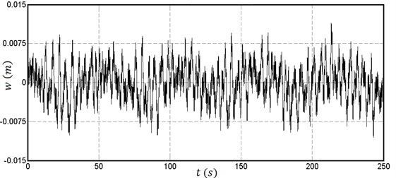
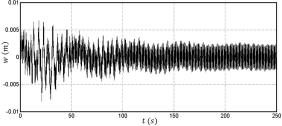
In Fig. 6, time response of the system in the lateral axis normal to the direction of the initial displacement is shown. It should be noted that in deviated drilling aside of gyroscopic effects which cause the drill string to vibrates in another axis, the components of weight force would vibrate between two axes. This force causes vibrations with low frequencies and high amplitudes compared to vertical drilling. In Fig. 6 effects of mud flow rate is not considered so that other effects can be observed.
Instability and time response of a deviated drill string is considered using finite element method and effects of drilling mud flow rate is studied which acts like a damper. Because of deviation angle, weight of drill string causes deflection in drill string which rotates and makes whirling in vibration. The results show how change of weight on bit, mod flow rate, angular velocity and deviation angle makes drill string instable.
Fig. 5Phase plan for a point in drill pipe (x= 200 m) in response to a H=10+10sin10πt/3 with Ω= 100 rpm: a) α= 0, Q=0, b) α=0, Q= 50 lit/s, c) α= 3°, Q=0, d) α= 3°, Q= 50 lit/s
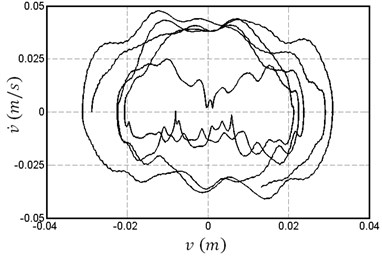
a)
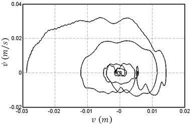
b)
c)
d)
Fig. 6Amplitude of transverse vibration in the direction of w in response to H=10+10sin10πt/3 with Ω= 100 rpm: a) Q=0, b) Q= 50 lit/s
a)
b)
4. Conclusions
In this paper effects of mud flow rate, weight on bit, angular velocity and deviation angle on stability and time response of an inclined drill string are analyzed. Considering rotation and deviation angle and using Paidoussis formulations for modeling mud flow rate around drill string makes this model unique and give results which is not considered yet. Finite element method is used to discrete formulations. Angular velocity, mud flow rate and weight on bit are the main parameters affecting the stability of the drill string. It is found that deviation angle causes stability criteria curvature to be lower. This means the system is more sensitive to drill string parameters. This phenomenon is more critical when nonlinear terms are considered. It should also be noted that decreasing weight on bit and increasing mod flow rate as well as deviation angle lead to lower natural frequencies.
References
-
Abbassian F., Dunayevsky V. A., Judzis A. Dynamic stability of drill strings under fluctuating weight on bit. SPE Drilling and Completion, Vol. 8, Issue 2, 1993, p. 84-92.
-
Jansen J. D., van den Steen L. Active damping of self-excited torsional vibrations in oil well drillstrings. Journal of Sound and Vibration, Vol. 179, Issue 4, 1995, p. 647-668.
-
Jansen J. D. Non-linear rotor dynamics as applied to oil well drill string vibrations. Journal of Sound and Vibration, Vol. 147, Issue 1, 1991, p. 115-135.
-
Yigit A. S., Christoforou A. P. Coupled axial and transverse vibrations of oil well drill strings. Journal of Sound and Vibration, Vol. 195, Issue 4, 1996, p. 617-627.
-
Christoforou A. P., Yigit A. S. Dynamic modelling of rotating drill strings with borehole interactions. Journal of Sound and Vibration, Vol. 206, Issue 2, 1997, p. 243-260.
-
Yigit A. S., Christoforou A. P. Coupled torsional and bending vibrations of drill strings subject to impact with friction. Journal of Sound and Vibration, Vol. 215, Issue 1, 1998, p. 167-181.
-
Khulief Y. A., Al-Naser H. Finite element dynamic analysis of drill strings. Finite Elements in Analysis and Design, Vol. 41, Issue 13, 2005, p. 1270-1288.
-
Apostal M. C., Haduch G. A., Williams J. B. A Study to determine the effect of damping on finite-element-based, forced-frequency-response models for bottom hole assembly vibration analysis. Proceedings of the 65th SPE Annual Technical Conference and Exhibition, Orleans, LA, 1990.
-
Berlioz A., der Hagopian J., Dufour R., Draoui E. Dynamic behavior of a drill string: experimental investigation of lateral instabilities. Journal of Vibration and Acoustics, Vol. 118, 1996, p. 292-298.
-
Vandiver J. K., Nicholson J. W., Shyu R. J. Case studies of the bending vibration and whirling motion of drill collars. SPE Drilling Engineering, Vol. 5, Issue 4, 1990, p. 282-290.
-
Gulyaev V. I., Lugovoi P. Z., Gaidaichuk V. V., Solov’ev I. L., Gorbunovich I. V. Effect of the length of a rotating drill string on the stability of its quasi-static equilibrium. International Journal of Applied Mechanics, Vol. 43, Issue 9, 2007, p. 1017-1023.
-
Paidoussis M. P., Luu T. P., Prabhakar S. Dynamics of a long tubular cantilever conveying fluid downwards, which then flows upwards around the cantilever as a confined annular flow. Journal of Fluids and Structures, Vol. 24, 2008, p. 111-128.
-
Paidoussis M. P. Fluid Structure Interactions, Slender Structure and Axial Flow. Vol. 1. Academic Press, London, UK, 1998.
-
Yigit A. S., Scott R. A., Ulsoy A. G. Flexural motion of a radically rotating beam attached to a rigid body. Journal of Sound and Vibration, Vol. 121, 1988, p. 201-210.
-
Choi S. H., Pierre C., Ulsoy A. G. Consistent modeling of rotating Timoshenko shafts subject to axial loads. Journal of Vibration and Acoustics, Vol. 114, 1992, p. 249-259.
Cited by
About this article

