Abstract
The creeping behaviors between hoisting rope and friction lining in the process of deep coal mine friction transmission are investigated in this study. Rope tension during the hoist lifting and lowering process is obtained first. Then, the calculation models of creeping area, creeping quantity and creeping velocity are established. The rope tension and creeping quantity are measured by a self-designed experiment device to verify the model validity. Subsequently, effects of the kinematic parameters on creeping behaviors are explored. The results show that increases of the terminal mass ratio, terminal mass, maximum acceleration, maximum speed cause expanding trends of overall ranges of the maximum creeping velocity, respectively. Less creep is beneficial to improve the friction transmission safety, service life of friction lining and good anti-slip properties. The most effective way to decrease the creep is to increase the container weight.
1. Introduction
More than 90 % of the coal output relies on the underground mining in China. Among this, mines with the depth of more than 500 m are 40 %, and the depth of 40 more mines has exceeded 1000 m. The mining depth presents an increasing trend with an annual rate of 8-12 m [1]. A multi-rope friction hoist, which is operated by friction between ropes and friction lining fixed on the surface of a pulley, have wide applications in deep (> 700 m) large modern coal mines [2, 3].
During friction lifting, as the great mining depth, changing rope length and elastic characteristics of steel wire rope result in dynamic rope tensions [4, 5]. A rope with dynamic tensions wrapped around a pulley cause elastic deformation of the rope and the friction lining, thus a small local slip between the rope and friction lining, i.e. creeping [6, 7], occurs. The accumulation of this creeping result in sliding friction, and this is a source of friction force between the rope and friction lining. Appropriate creeping is the precondition for hoist lifting capacity. While, the excessive creeping will induce rope slipping accidents due to the insufficient friction force, which might cause the destruction of mine equipment and even casualties. Therefore, it is of great significance to study the creeping behaviors between the rope and friction lining in the process of friction transmission.
In recent years, many scholars have performed researches on sliding friction between the rope and friction lining, Peng et al. [8]studied the effect of contact stress on the friction coefficient under low sliding speed and found that an increase in contact stress of lining within a certain range will increase the friction coefficient. In his recent article [9], the friction heat conduction and entrainment of two friction linings in the high-speed slide accident of a mine friction hoist were analyzed. Ma et al. [10, 11] studied the sliding friction and wear properties of the friction lining under different contact stress, with friction-promoting grease applied, and found that grease can effectively reduce the lining’s wear and tear in the process of sliding. The rheological characteristics of newly-developed friction-promoting grease in China were also studied. Zhang et al. [12] studied the effects of the microstructure and basic properties of different friction linings on friction. Three commercial grade linings with similar compositions were investigated (trade names: K25, G30, and GM-3). Reciprocating sliding friction and wear tests indicated that higher contents of methylene and filler improve the friction coefficient. Hao et al. [13] calculated the real contacting area with the adoption of the in-situ observation method (using a VW9000 high-speed microscope camera) and the gray-scale method. The results of the experiments show that the friction coefficient was proportional to the real conducting area. Wang et al. [14] investigated the roles of hoisting parameters on contact states, slip amplitude and stress distributions along the contact path using finite element analyses. From literature studies mentioned above, previous efforts have been focused on the sliding friction between the friction lining and rope. However, the researches of sliding friction are most based on the rope slipping. The research purposes are mostly focused on the mechanism of friction and material properties. Few studies of creeping behaviors and the correlation of creeping parameters and safety between the rope and friction lining during dynamic hoisting have been reported.
This study aims to investigate the creep state between the rope and friction lining before rope slipping. Creeping behaviors, including creeping area, creeping velocity and creeping quantity between the rope and friction lining are obtained in the present study. The results are conducive to reveal the creep mechanism between the rope and friction lining. The risk of rope skid can be predicted by measuring the creeping velocity. The results also consist in the guiding significance in the aspect of friction experimental parameters between the rope and friction lining. Simulink simulations and experimental device are employed in Section 2 to investigate the dynamic rope tension during lifting and lowering processes in a deep coal mine. The creeping area between the steel rope and friction lining are investigated. A simulation model of creeping velocity between the rope and friction lining is established in Section 3. Then the effects of different parameters of friction lining, terminal mass and kinematics on dynamic creeping behaviors between the rope and friction lining are discussed.
2. Creeping area between steel rope and friction lining
2.1. Theoretical models
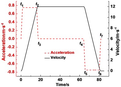
Fig. 1 shows the principle and structure of multi-rope friction hoist. Several wire ropes wrap around the friction pulley. The friction lining with rope grooves is attached to the surface of the pulley. The friction hoist system applies the friction force between the ropes and corresponding rope grooves on the friction lining to lift and lower the containers, respectively. The tail ropes hanging at the shaft bottom connect the two containers to balance the tension difference caused by the gravity of the ropes. The container speed curve on the lift side is shown in Fig. 2. The dedicated tension-balance device is required in the multi-rope friction hoist. The purpose is to ensure the tension balance between the ropes [15]. Therefore, for research convenience, several ropes are simplified into one assuming that the vertical ropes have the same dynamic properties [16]. Movement coordinates are located at the left and right tangents of the friction pulley with positive directions of coordinate axes pointing upwards and downwards, respectively.
Differential equations of the tension, , of one simplified rope at the left tangent (point A) of the friction pulley during hoisting stages of acceleration (0-), constant speed (-) and deceleration (-) are written as[17, 18]:
where, is the rope tension of a tangent point (Fig. 1 point A or B). is the elastic modulus (MPa). is the rope cross sectional area (mm2). is the acceleration of gravity. is the acceleration. is the terminal mass (kg). is the lifting rope linear density (kg∙m−1). is the tail rope linear density (kg∙m−1). is the lifting rope length. is the tail rope length. - is the change moment of acceleration.
Fig. 1Schematic of multi-rope friction hoist system in coal mine
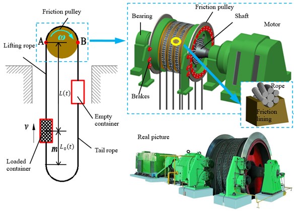
Fig. 2Hoisting speed and acceleration curve
When the parameter contains the mass of container and minerals according to the speed curve as shown in Fig. 2, is the rope tension of tangent point A. When the parameter contains the mass of container only and converts the speed of Fig. 2 to negative values, changes the rope tension of tangent point B. The Rayleigh-Ritz method [18] is employed to deal with the lifting rope and tail rope that one third of which is added to . The simulation model is established by MATLAB-Simulink [19].
Fig. 3(a) presents a rope wrapped around the friction pulley with the wrap angle, . The pull force at the left-end is (corresponding to the rope tension of point A), and the hold force at the right-end of the rope is (corresponding to the rope tension of point B). The problem is statically indeterminate, unless the pull force is increased to produce the state of impending gross slip of the rope over the friction pulley. In the latter case, rope tensions, and , satisfy the Euler formula as described in Eq. (2) [20, 21]:
where, is the friction coefficient. The friction coefficient is assumed to be constant during hoisting. The design value of the coefficient remains 0.25 in the mine friction hoist in China [8-11].
Fig. 3Rope tension distribution in instantaneous transmission in friction hoist
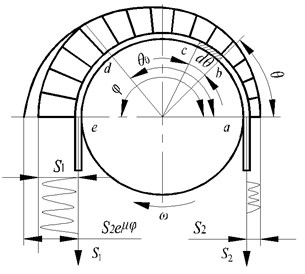
a)
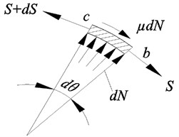
b)
In the actual working process of the friction hoist, the pull force of rope is not large enough to produce the state of impending gross slip. Hence, the wrap angle is divided into two parts, i.e. and -, respectively. The tension of one side of the infinitesimal section of wire rope (Fig. 3(b)) satisfies the Euler formula within [21]:
Wire rope and friction lining are elastomer. The changes of tension induce the stretch and shrink of the rope. The friction lining also produce elastic deformation under the action of the rope pressure. This induces the relative slip, i.e. creeping, between the friction lining and rope. The creeping occurs in the area . There is no creeping in area -because the rope tension is equal [22, 23]. When the difference between tension and increases, the creeping area increases to provide enough friction force. When the creeping area continue expanding and is equal to the wrap angle, the friction transmission reaches the critical state of impending gross slip. The friction force between the friction lining and the rope reaches the limit value. Once the tension difference fluctuates and exceeds the allowable value, the rope would produce a gross slip on the entire wrap angle and induce a transmission failure.
The creeping area changes with the variation of tension difference between and . The relationship between them is [24, 25]:
2.2. Experimental device
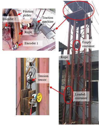
To verify the accuracy of the calculation results, an experimental device which can simulate the dynamic friction transmission of friction hoist is designed. The equipment can measure the rope tension and creeping quantity between the rope and friction lining. The principle is shown in Fig. 4. Photos of the experiment device are shown in Fig. 5. The friction pulley is driven by a traction machine according to a certain speed curve. The friction lining (K25) with rope groove is fixed on the pulley surface. The steel wire rope wrapped around the pulley with one end hanging a loaded container and the other end hanging an empty container. Tension sensors are installed between wire rope and the containers to measure the rope tension. The containers move along the vertical direction on the guide rail through the guide shoes. Encoder 1 is installed close to the tangent point of rope relative to the pulley to measure the vertical displacement of rope. A rubber roller is installed between the encoder and rope. The rubber roller with rope groove can ensure that there is no slip between the rope and the roller. Encoder 2 is installed at the friction pulley axle to measure the rotate angle. The arc length of the friction pulley can be obtained by multiplying the rotational speed by the friction pulley radius.
Fig. 4Schematic diagram of dynamic friction transmission experiment device of friction hoist
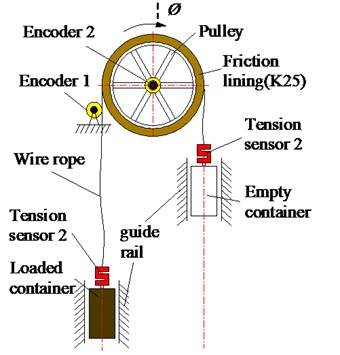
Fig. 5Photos of dynamic friction transmission experiment device
2.3. Results and discussion
Table 1 lists the parameters of the experimental system.
Table 1Parameters of experimental system
Shaft parameters | Load mass (kg) | 37.75 |
Container mass (kg) | 32.66 | |
Lifting height (m) | 2 | |
Multi-rope friction hoist | Friction pulley diameter (m) | 0.64 |
Wrap angle (°) | 180 | |
Friction coefficient of the friction lining | 0.25 | |
Lifting rope | Type | 6×19WS+FC |
Diameter (mm) | 8 | |
Mass per meter of lifting rope (kg) | 0.24 | |
Elastic modulus (MPa) | 93200 | |
Number | 1 | |
Kinematic parameters | Initial static tension of lifting side (N) | 691.22 |
Initial static tension of lowering side (N) | 369.95 | |
Acceleration (m/s2) | 0.8 | |
Maximum speed (m/s) | 1 | |
Acceleration time (s) | 1.1 | |
Constant speed time (s) | 1.1 |
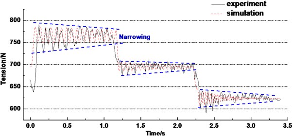
Set the parameters in the rope tension model according to Table 1. Fig. 6 shows the experiment and simulation results of rope tension of lifting side, respectively. It can be seen that the goodness of fit between the experiment and simulation results is high. Both the curves present the same change rule at acceleration, constant speed and deceleration stage, respectively. The rope tension value and the tension range are larger at the acceleration and deceleration stage. The tension is relatively stable at a constant speed stage. In addition, the range of rope tension presents a narrowing trend at the three stages. The reason can explain as follows, when the hoist system starts accelerating and decelerates, the friction force produced by the rope and friction lining does work on the rope which increases the tension range. Then the tension decays gradually and tends to be stable because of the good elasticity and damping characteristics of steel wire rope. The energy is absorbed and then is dissipated.
Fig. 6Rope tension of lifting loaded container
Typical hoisting parameters of a multi-rope friction hoist system of a main shaft in a mining corporation in China are shown in Table 2.
Table 2Parameters of hoist system
Shaft parameters | Load mass (t) | 40 |
Container mass (t) | 50 | |
Lifting height (m) | 800 | |
Height from tangent point to lock port (m) | 30 | |
Multi-rope friction hoist | Type | JKM-4.6×6 |
Friction pulley diameter (m) | 4.6 | |
Wrap angle (°) | 195 | |
Friction coefficient of the friction lining | 0.25 | |
Radial thickness of the friction lining (mm) | 115 | |
Elastic modulus of the friction lining (MPa) | 50 | |
Lifting Rope | Type | 6×36WS+FC |
Diameter (mm) | 46 | |
Mass per meter of lifting rope (kg) | 8.52 | |
Minimum breaking force (N) | 1650 | |
Elastic modulus (MPa) | 105 | |
Number | 6 | |
Tail rope | Type | Flat rope P8 × 4 × 19+FC |
Size(mm) | 196×31 | |
Mass per meter of tail rope (kg) | 17.04 | |
Number | 3 | |
Kinematic parameters | Initial static tension of lifting side (N) | 9.55×10⁵ |
Initial static tension of lowering side (N) | 5.63×10⁵ | |
Maximum acceleration (m/s2) | 0.75 | |
Maximum speed (m/s) | 12 |
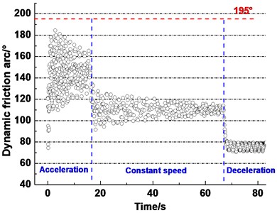
Set the parameters in the rope tension model according to Table 2 and calculate the creeping area according to the Eq. (4). It is clearly seen from Fig. 7 that the creeping area between the rope and friction lining always presents the fluctuating downward trend with increasing time and exhibits three stages corresponding to three lifting stages. The creeping area reached the largest point, 184.4°, at the acceleration stage among the three stages. And the minimum value is 70.7° at the decrease stage. During acceleration, the overall range of creeping area decrease from 74.3°-184.4° to 128.6°-165.3°. During the constant speed, the overall range of creeping area decreases from 91.5°-127.6° to 107.2°-114°. During deceleration, the overall range of creeping area varies between 70° and 80°.
Fig. 7Dynamic creeping area in typical work conditions in friction hoist
During acceleration, the overall range of creeping area is larger than the other stages. Thereby, enough friction force between the friction lining and rope is provided to overcome the inertia force [26]. In the other words, the transmission capacity between the rope and lining improves with the creeping area increasing. But, in order to avoid gross slip between the friction lining and rope, the creeping area should not be too large. Therefore, it is greatly necessary to find a suitable creeping area to obtain the best combination of high friction transmission capacity and good anti-slip property.
3. Creeping velocity and creeping quantity between steel rope and friction lining
3.1. Theoretical models
The creep source consists of two parts, i.e. the deformation of friction lining and the deformation of rope, respectively. In the real practice, the radial deformation of rope is small and slow enough that can be ignored [27]. Thus, let’s assume that the rope produces longitudinal deformation only. The deformation of friction lining is very small because of the compact size. In addition, the tangential force on the friction pulley is much smaller than the radial force [28]. Therefore, only the radial deformation of the friction lining is considered.
When the infinitesimal segment of rope is running within the creeping area , the different tension of both sides of the infinitesimal segment induces the different strain of rope. The strain of rope at angle is obtained by the Hooke’s law:
where, is the tensile stiffness of rope. Take the derivatives of Eq. (5) with respect to :
It can be seen from Eq. (6) that the rope strain rate is the ratio of tension strain rate and rope tensile stiffness along the direction of arc. Transform Eq. (6) into differential form and integrate from to :
and represent the strain at and , respectively. The creeping quantity is the length change of wire rope caused by the tension change. Assuming that the differential of length change is , then:
where, is the friction pulley diameter, is the number of lifting rope. Take the derivatives of Eq. (8) with respect to time, . The creeping velocity of rope relative to the friction lining can be obtained:
The rope tension is equal in each point when the infinitesimal segment of rope runs out of the creeping area (-). The deformation caused by the rope is 0. Therefore, the creeping velocity caused by deformation of rope can be divided into two parts:
The friction lining produce deformation under the rope pressure. The frictional stress and contact stress influence each other. Their interaction should be considered simultaneously [27]. Thus, the contact stress of friction lining of each position on the friction pulley are calculated. The contact stress of friction lining are different inside the creeping area and outside the creeping area. The contact stress of friction lining can be expressed as:
The radial deformation of friction lining infinitesimal segment can be expressed as:
where, is the radial thickness. is the elastic modulus.
The creeping velocity caused by deformation of friction lining can be expressed as:
where, is the operation angular velocity of the friction pulley.
If the origin of coordinates is located at tangent point A, the deformation of the wire rope is “shortened” when it closes to the tangent point B. The deformation direction of rope points to the origin of coordinates. The direction of creeping velocity caused by deformation of friction lining is consistent with the direction of . The direction of movement of the friction lining relative to the rope is departing from the origin of coordinates. Therefore, the actual creeping velocity between the rope and friction lining is the sum of both:
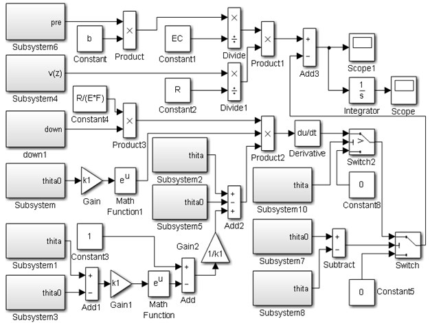
Fig. 8 shows the simulation model of the creeping velocity. A value of Scope is the creeping velocity between the rope and friction lining. Subsystem, Subsystem 3, Subsystem 5 and Subsystem 7 are the submodels of . Subsystem 1, Subsystem 2, Subsystem 8 and Subsystem 10 are the submodels of . Subsystem 6 is the submodel of , Subsystem 4 is the submodel of hoist speed. Subsystem 9 is the submodel of . The value of Scope1 is the creeping velocity.
Fig. 8Simulation model of creeping velocity between rope and friction lining
3.2. Results and discussion
Fig. 9(a) shows the creeping velocity between the rope and friction lining in a lifting cycle. The creeping velocity presents different patterns at stages of acceleration, constant speed and deceleration. The overall rule of creeping velocity presents a trapezoidal shape which is like the given speed curve, i.e. up-smooth-down. The creeping velocity reaches the maximum value (10.2 mm/s, –6.4 mm/s) at the start of acceleration stage. Forward and reverse creeping appears at the moment of hoist start. Then the creeping maintains a single direction and increases gradually at the acceleration stage. The creeping velocity change stable between 4 to 7 mm/s at the constant speed stage. At the deceleration stage, the creeping velocity declines gradually and tends to zero. The creeping velocity is set to 0 when the infinitesimal segment runs out of the wrap angle.
Fig. 9(b) shows the creeping quantity between the rope and friction lining in a lifting cycle. It is obtained by the integral of creeping velocity. It indicates the total creeping quantity of one point on the friction lining of the pulley. It can be seen that the creeping quantity also presents three variations, i.e. increases from slow to fast, increases steadily, decreases steadily and converges to zero, at stages of acceleration, constant speed, deceleration, respectively. The total creeping quantity is 178 mm over a lifting cycle. The creeping phenomenon is the most intense at the start of acceleration.
Fig. 9Creeping velocity and creeping quantity between rope and friction lining
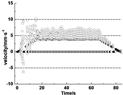
a) Creeping velocity
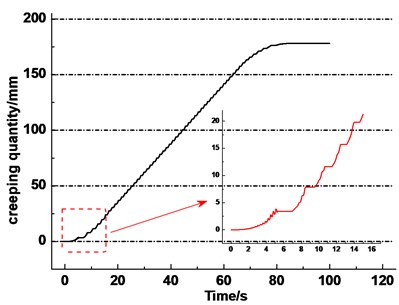
b) Creeping quantity
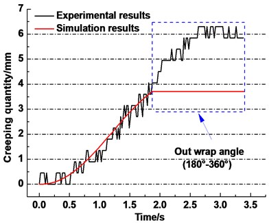
To verify the accuracy of the calculation results, the experiments are carried out with the device mentioned in Section 2.2. The displacement difference between the two encoders is considered to be the total creeping quantity between the rope and friction lining. The calculate target of the model is the meeting point (point A in Fig. 1) on the pulley. Then the lifting height is selected to be equal to 2 meters. So, the displacement difference values of half lifting process can be regarded as the creeping quantity of one point on the friction pulley.
Set the parameters in the simulation model according to Table 1 and calculation. Fig. 10 shows the results of the experiment and simulation of creeping quantity between the rope and friction lining, respectively. The curve in the blue dotted box represents that the selected point on the friction lining rolls out of the wrap angle. The experiment result is similar to the simulation result, i.e. the creeping quantity presents an increasing trend. And the curve is divided into three stages, i.e. acceleration, constant speed and deceleration, similar to the given displacement of the lifting.
Fig. 10Simulation and experimental results of creeping quantity between rope and friction lining
3.2.1. Effect of different parameters on creeping velocity
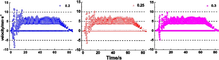
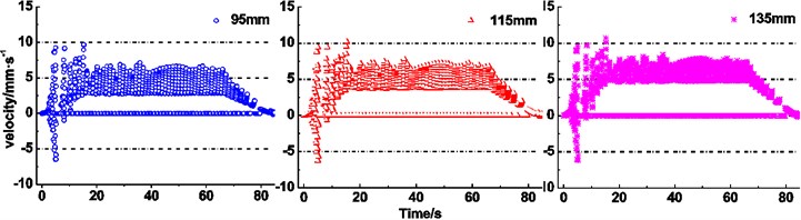
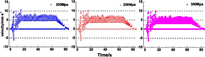
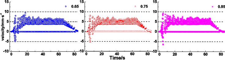
There are many varieties of friction lining used in the mine hoist [12, 13]. The creeping velocity of different lining performance parameters is obtained as shown in Fig. 11(a)-(c). It is clearly seen from Fig. 11(a) that an increase of friction coefficient between the rope and friction lining induces ranges of the maximum creeping velocity changing from –8.7-12.1 mm∙s-1 to –4.8-9.7 mm∙s-1, from 3.7-8.0 mm∙s-1 to 3.7-7.6 mm∙s-1, and from 0-6.6 mm∙s-1 to 0-6.7 mm∙s-1, respectively, during stages of acceleration, constant speed and deceleration, which indicates the narrowing trend. Meanwhile, during the stage of acceleration, creeping velocity presents the decentralized state. Fig. 11(b) presents the expanding trend of the creeping velocity range, i.e. varying from –6.5-9.7 mm∙s-1 to –6.1-10.8 mm∙s-1, from 2.8-7.1 mm∙s-1 to 4.6-8.4 mm∙s-1, and from 0-6.2 mm∙s-1 to 0-7.4 mm∙s-1, respectively, during stages of acceleration, constant speed and deceleration with increasing radial thickness of friction lining. It is obviously observed from Fig. 11(c) that an increase of elastic modulus of friction lining causes the maximum creeping velocity narrowing from –6.1-10.7 mm∙s-1 to –6.4-9.9 mm∙s-1 during acceleration. During the stage of the constant speed, the range of maximum creeping velocity varies from 4.6-8.4 mm∙s-1 to 3.1-7.4 mm∙s-1, which indicates the narrowing trend. But the constant interval of the creeping velocity expands. During deceleration, the range of maximum creeping velocity narrows from 0-7.4 mm∙s-1 to 0-6.4 mm∙s-1 with increasing elastic modulus.
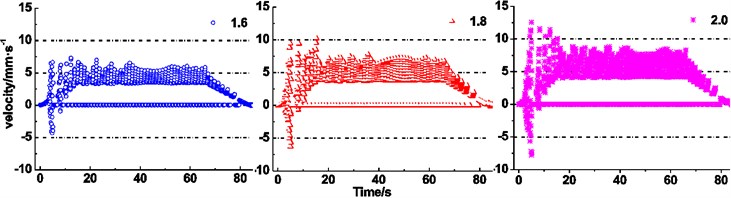
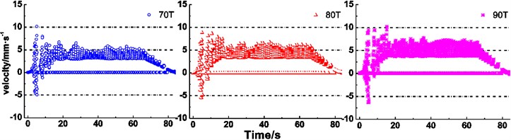
It is clearly seen from Fig. 11(d) that the ranges of the maximum creeping velocity changes from –4.3-7.3 mm∙s-1 to –7.8-12.6 mm∙s-1, from 3.4-7.0 mm∙s-1 to 4.1-8.8 mm∙s-1, and from 0-5.9 mm∙s-1 to 0-8.3 mm∙s-1, respectively, during stages of acceleration, constant speed and deceleration, when the terminal mass ratio between the lifting side and lowering side increases from 1.6 to 2.0. Meanwhile, the constant interval of creeping velocity presents the expanding trend during every stage. Fig. 11(e) presents the expanding trend of the creeping velocity range, i.e. varying from –5-10.1 mm∙s-1 to –6.3-10.1 mm∙s-1, from 3-6.5 mm∙s-1 to 3.7-7.8 mm∙s-1, and from 0-4.9 mm∙s-1 to 0-6.8 mm∙s-1, respectively, during stages of acceleration, constant speed and deceleration with increasing terminal mass of lifting side with the terminal mass ratio 1.8.
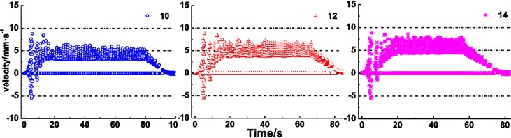
In the following discussion, the duration time of the acceleration or constant speed is adjusted to keep the hoist height of 800 m. It is obviously observed from Fig. 11(f) that the ranges of the maximum creeping velocity changes from –5-9.4 mm∙s-1 to –6.5-9.3 mm∙s-1, from 3.7-7.4 mm∙s-1 to 3.7-8.3 mm∙s-1, and from 0-6.3 mm∙s-1 to 0-6.8 mm∙s-1, respectively, with increasing of lifting maximum acceleration, which means that the increase of lifting maximum acceleration induce the expanding trend of the creeping velocity range. It is clearly seen from Fig. 11(g) that an increase of the maximum speed does not induce an obvious change in the overall range of the maximum creeping velocity in case of acceleration stage, which means that the overall range of maximum creeping velocity varies from –5.5 mm∙s-1 to 8.8 mm∙s-1. During the constant speed and deceleration, the overall ranges present an upward trend, i.e. changes from 3.1-6.4 mm∙s-1 to 4.3-8.5 mm∙s-1 and from 0-5.3 mm∙s-1 to 0-7.9 mm∙s-1, respectively.
Figs. 11(a)-(c) reveal the influences of relevant parameters of friction lining on creeping velocity between the rope and friction lining. It is obviously observed that increases of friction coefficient and elastic modulus, decreases of radial thickness cause narrowing trends of overall ranges of the maximum creeping velocity between the rope and friction lining, what reveals the deceleration of friction lining wear [29] and improvement of friction lining service life. The creeping velocity has a retroaction on the friction coefficient [30]. Therefore, the relationship between creeping velocity and friction coefficient is coupling. While the decrease of radial thickness reduces the wear of friction lining, the friction lining is easier to be lost than the wire rope in the friction pair. Hence, a sufficient thickness of friction lining is important to ensure the service life. Therefore, appropriate friction coefficient, size and elastic modulus of friction lining are beneficial to reduce the wear of friction lining and improve the service life. Figs. 11(d) and (e) show the influence of terminal mass on the creeping velocity. It is clearly seen from the figures that increases of terminal mass ratio and terminal mass of lifting side induce an increase of the creeping velocity between the rope and friction lining. While the decreases of terminal mass ratio and terminal mass of lifting side reduce the creeping velocity and thereby reduce the wear of friction lining, the terminal mass ratio and terminal mass of lifting side should be sufficient to ensure the hoisting efficiency [31]. Therefore, it is necessary to set an appropriate terminal mass to balance the relationship between the hoisting efficiency and the wear of friction lining. Figs. 11(f) and (g) show the influence of kinematic parameters of loaded container on the creeping velocity. It can be seen that the increases of maximum acceleration and maximum speed induce the increase of the creeping velocity between the rope and friction lining. Compared with the increase of maximum speed, the increase of maximum acceleration has remarkable influences on the intensification of creeping velocity at the acceleration stage. But the increase of maximum speed is more effective at the constant speed stage. The constant speed stage is longer than acceleration stage, thus the increase of maximum speed has more influence on the creeping velocity between the rope and friction lining. In addition, the increases of maximum acceleration and maximum speed are conducive to improve the transport efficiency of the friction hoist.
Fig. 11Creeping velocity between rope and friction lining under different parameters
a) Different friction coefficient
b) Different radial thickness
c) Different elastic modulus
d) Different terminal mass ratio
e) Different terminal mass
f) Different maximum accelerations
g) Different maximum speeds
The statistical results of creeping velocity are listed in Fig. 12. The figure shows the maximum creeping velocity and the range of creeping velocity of the constant speed, for the most of lifting time it is a constant speed. It can be seen that the maximum creeping velocity increases with increases of a radial thickness of lining, terminal mass and terminal mass ratio, respectively, and decreases with increasing the friction coefficient and elastic modulus, respectively. The maximum acceleration and maximum speed have no obvious effect on the maximum creeping velocity. The range of creeping velocity of constant speed presents moving up or expanding trend with increases of radial thickness of lining, terminal mass, terminal mass ratio, maximum acceleration and maximum speed, respectively. Only increases of the friction coefficient and elastic modulus induces the constant moving-down trend of the creeping velocity range, respectively. The results are divided into two categories using green and red arrows. Increases of the parameters corresponding to the red arrow are beneficial to the hoisting efficiency [31] but will cause an increasing creep. Increases of the friction coefficient and elastic modulus of friction lining material are the most effective ways to improve the hoisting efficiency and non-skid property.
3.2.2. Effect of different parameters on creeping quantity
The experiments of creeping quantity of different terminal mass, maximum accelerations and maximum speeds are carried out. The results are shown in Fig. 13. It is clearly seen from Fig. 13(a) that the creeping quantity rate presents an acceleration trend with the increasing terminal mass of lifting side. The total creeping quantity varies from 4 mm to 6 mm at the end of lifting. It is obviously observed from Fig. 13(b) that the creeping quantity starts from the same zero point and ends at the same point. The creeping quantity rates increase a little with the increasing acceleration. The total creeping quantity remains 5.5 mm with the increasing acceleration. It can be found from Fig. 13(c) that an increase of lifting speed cause the acceleration trend of creeping quantity rate. The total creeping quantity of three different lifting speeds reaches almost the same value, i.e. 6 mm at the end of lifting.
Fig. 12Statistical results of creeping velocity
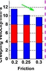
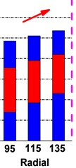
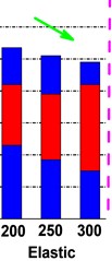
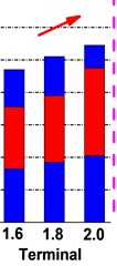
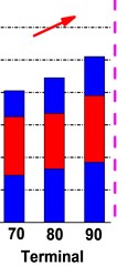
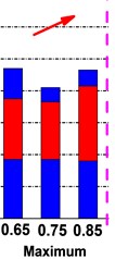
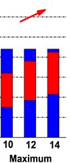

Fig. 13Experiment results of creeping quantity of different parameters
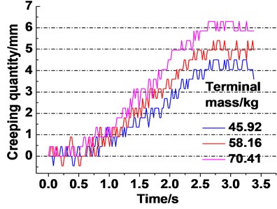
a) Different terminal mass
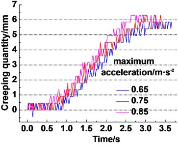
b) Different maximum accelerations
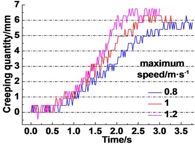
c) Different maximum speeds
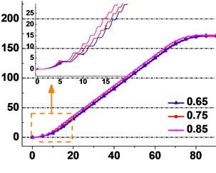
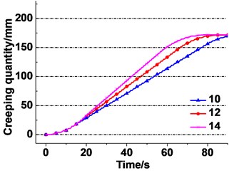
The creeping quantity between the rope and friction lining of the actual working condition as shown in Table 2 is obtained. The calculation results are shown in Fig. 14. It is clearly seen from Fig. 14(a) that the creeping quantity starts from the same zero point but rises at different rates. The creeping quantity with the friction coefficient of 0.2 is rising the fastest, which indicates the deceleration trend with increase of the friction coefficient. The total creeping quantity changes from 181.7 mmto 171.2 mm at the end of lifting, which indicates the decreasing trend. Fig. 14(b) presents the acceleration trend of the creeping quantity rate with increasing the radial thickness of friction lining. The total creeping quantity varies from 145.7 mm to 210 mm at the end of lifting. It is obviously observed from Fig. 14(c) that an increase of the elastic modulus of friction lining causes a deceleration trend of creeping quantity rate. The total creeping quantity decreases from 209 mm to 157.4 mm at the end of lifting.
Fig. 14Creeping quantity between rope and friction lining under different parameters
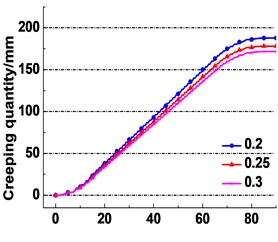
a) Different friction coefficient
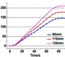
b) Different thickness
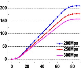
c) Different elastic modulus
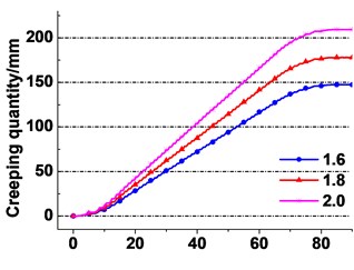
d) Different terminal mass ratio
e) Different terminal mass
f) Different maximum accelerations
g) Different maximum speeds
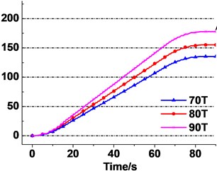
It is clearly seen from Fig. 14(d) that the creeping quantity of the terminal mass ratio of 2.0 is rising the fastest, which indicates the acceleration trend with increase of the terminal mass ratio. The total creeping quantity changes from 147.4 mmto 209.5 mm at the end of lifting, which indicates the decreasing trend. Fig. 14(e) presents an acceleration trend of the creeping quantity rate with increasing terminal mass of lifting side. The change law of the calculate result is similar to the experiment’s as shown in Fig. 13(a). The total creeping quantity varies from 135.5 mm to 178 mm at the end of lifting.
It is obviously observed from Fig. 14(f) that the creeping quantity starts from the same zero point and ends at the same point. The creeping quantity rates increase a little with the increasing acceleration. The total creeping quantity remains 170.9 mm with the increasing acceleration. It is obviously observed from Fig. 14(g) that an increase of lifting speed causes the acceleration trend of creeping quantity rate. The total creeping quantity of three different lifting speeds reaches the same point, i.e. 171.5 mm at the end of lifting. The change law of the calculation results is similar to the experiment’s as shown in Fig. 13(b) and (c).
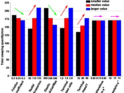
As compared with the creeping area and creeping velocity mentioned above, the creeping quantity, as an accumulation parameter of time, is easily measured. It is considered to be a monitoring value which could control the rope slipping risks. The increases of friction coefficient and elastic modulus, decreases of radial thickness, terminal mass ratio and terminal mass of lifting side cause decreases of the creeping quantity between the rope and friction lining, which reveals the reduction of a gross slip risk of the rope over the friction pulley [32]. It can be seen from Fig. 14(f) and (g) that increases of maximum speed and maximum acceleration cause a faster ascent of creeping quantity, respectively. But the influence of maximum speed is more effective under the selected gradient. Fig. 15 shows the statistical results of total creeping quantity of different parameters. Increases of a radial thickness, terminal mass and terminal mass ratio cause an increase of total creeping quantity, which would enhance the hoisting ability but reduce the anti-slip property at the same time. Relatively, an increase of the friction coefficient and elastic modulus of friction lining is the best way to improve the anti-slip property with insufficient lifting loss. Considering the service life of the friction lining and the hoisting efficiency, it is necessary to find the appropriate parameters of friction lining, terminal mass and kinematics to obtain the sufficient hoist capacity, service life and good anti-slip properties.
Fig. 15Statistical results of creeping quantity
4. Conclusions
Based on tensions of the hoisting rope at left and right tangents of the friction pulley during hoisting, the creeping area between the rope and friction lining around the friction pulley is calculated. The creeping area reaches maximum 184.4°, at the acceleration stage among the three stages. The transmission capacity between the rope and lining improves with increasing the creeping area.
Formulas of the creeping velocity between the rope and friction lining are obtained. The creeping quantity, integration of creeping velocity is considered to be a monitoring value which can prevent from rope slipping accidents. The model validity is verified by a self-designed experiment device. The overall ranges of maximum creeping velocity and creeping quantity in distinct hoisting conditions are –7.6-12.8 mm∙s-1 and 0-209 mm, respectively.
Increases of the radial thickness of friction lining, terminal mass ratio, terminal mass of lifting side, maximum acceleration, maximum speed all cause expanding trends of overall ranges of the maximum creeping velocity between the rope and friction lining, respectively. Increases of friction coefficient and elastic modulus, decreases of radial thickness, terminal mass ratio and terminal mass of lifting side cause decreases of the creeping quantity between the rope and friction lining, respectively. The most effective way to decrease a creep, without hoist efficiency loss, is to increase the container weight. Appropriate parameters of friction lining, terminal mass and kinematics are necessary to be found to improve the hoist safety and reliability.
References
-
Zhang D. K. Research on the friction transmission in mine friction hoist. Proceedings of the 12th National Conference on Tribology and the 2015 National Youth Tribology Conference, Chengdu, China, 2015.
-
Yao J. N., Xiao X. M. Effect of hoisting load on transverse vibrations of hoisting catenaries in floor type multirope friction mine hoists. Shock and Vibration, Vol. 9, Issue 2016, 2016, p. 1-15.
-
Wang D. G., Zhang D. K., Ge S. R. Effect of terminal mass on fretting and fatigue parameters of hoisting rope during a lifting cycle in coal mine. Engineering Failure Analysis, Vol. 36, Issue 1, 2014, p. 407-422.
-
Wang D. G., Zhang D. K., Mao X. B., et al. Dynamic friction transmission and creeping characteristics between hoisting rope and friction lining. Engineering Failure Analysis, Vol. 57, Issue 1, 2015, p. 499-510.
-
Imanishi E., Nanjo T., Kobayashi T. Dynamic simulation of wire rope with contact. Journal of Mechanical Science and Technology, Vol. 23, Issue 4, 2009, p. 1083-1088.
-
Huang W., Liu H. X., Lian Y. S., et al. Modeling nonlinear creeping and recovery behaviors of synthetic fiber ropes for deepwater moorings. Applied Ocean Research, Vol. 39, Issue 1, 2013, p. 113-120.
-
Kmet S., Mojdis M. Time-dependent analysis of cable nets using a modified nonlinear force-density method and creeping theory. Computers and Structures, Vol. 148, 2015, p. 45-62.
-
Peng Y. X., Zhu Z. C., Chen G. A. Effect of tension on friction coefficient between lining and wire rope with low speed sliding. Journal of China University of Mining and Technology, Vol. 17, Issue 3, 2007, p. 409-413.
-
Peng Y. X., Zhu Z. C., Tong M. M., et al. Friction heat conduction and entransy of friction lining. Industrial Lubrication and Tribology, Vol. 65, Issue 5, 2013, p. 305-310.
-
Ma W., Zhu Z. C., Xu L. Sliding friction and wear properties of friction linings with friction-promoting grease applied. Proceedings of the Institution of Mechanical Engineers, Part J: Journal of Engineering Tribology, Vol. 228, Issue 6, 2014, p. 595-607.
-
Ma W., Zhu Z. C., Peng Y. X., et al. Rheological Characteristics of a new kind of friction-promoting grease. Journal of Testing and Evaluation, Vol. 42, Issue 6, 2014, p. 1493-1500.
-
Zhang D. K., Chen K., Zhang X. J. Comparison of the thermophysical properties, microstructures, and frictional behavior of lining materials used in mine hoists. Wear, Vol. 354, Issue 355, 2016, p. 1-9.
-
Hao T. Q., Zhang D. K., Chen K. Friction mechanism in dynamic slide process of GM-3 friction liner. Tribology, Vol. 36, Issue 2, 2016, p. 177-184.
-
Wang D. G., Li X. W., Wang X. R., et al. Effects of hoisting parameters on dynamic contact characteristics between the rope and friction lining in a deep coal mine. Tribology International, Vol. 96, Issue 1, 2016, p. 31-42.
-
Feng H. L., Ma W., Li J. S., et al. Dynamic response analysis of steel rope tension balance device in ultra-deep coal mine. Journal of Henan University of Science and Technology (Natural Science), Vol. 37, Issue 1, 2016, p. 9-14.
-
Wang P., Xiao X. M., Ding B. H., et al. Dynamic simulation of wire rope of mine hoist in lifting process. Hoisting and Conveying Machinery, Vol. 7, 2009, p. 84-87.
-
Yan S. R., Wen B. C. Dynamic simulation of rope-container system in the hoist process in shaft hoist. The Chinese Journal of Nonferrous Metals, Vol. 2, 1998, p. 618-622.
-
Guo Y. B., Zhang D. K., Wang D. G. Theoretical modeling and variation law of dynamic friction angle of mining friction hoist. Journal of China Coal Society, Vol. 40, Issue 1, 2015, p. 2207-2212.
-
Li J. S., Zheng W. G. Creep sliding and its measurement of friction hoist. Journal of Mining Machinery, Vol. 1, 1986, p. 16-22.
-
Lubarda V. A. Determination of the belt force before the gross slip. Mechanism and Machine Theory, Vol. 83, 2015, p. 31-37.
-
Childs T. H. C. The contact and friction between flat belts and pulleys. International Journal of Mechanical Sciences, Vol. 22, Issue 2, 1980, p. 117-126.
-
Pietra L. D., Timpone F. Tension in a flat belt transmission: experimental investigation. Mechanism and Machine Theory, Vol. 70, Issue 6, 2013, p. 129-156.
-
Zhu C. J. Problem of elastic slip in belt drives and elastic band brake. Journal of Mechanical Transmission, Vol. 18, Issue 2, 1994, p. 26-30.
-
Zhang L. C. Discussions on the pressure formula of friction liner. Coal Mine Design, Vol. 3, 1989, p. 35-37.
-
Srivastava N., Haque I. A review of belt and chain continuously variable transmissions: dynamics and control. Mechanism and Machine Theory, Vol. 44, Issue 1, 2009, p. 19-41.
-
Huang P., Yang Q. Theory and contents of frictional mechanics. Friction, Vol. 2, Issue 1, 2014, p. 27-39.
-
Tan B., Du R. S., Yang S. Z. Research on the measuring sensor technology of steel rope diameter. Measurement Technology, Vol. 2, Issue 1, 1995, p. 4-6.
-
Guo Y. B., Zhang D. K., Wang D. G., et al. Dynamic distribution of contact stress of friction lining in the process of friction transmission. Journal of Vibroengineering, Vol. 18, Issue 7, 2016, p. 4207-4221.
-
Xu L. Tribological Behavior and Modification of Friction Lining for Mine Hoist under Severe Conditions. Ph.D. Thesis, China University of Mining and Technology, Xuzhou, China, 2010.
-
Xu L., Zhu Z. C., Chen G. A. Analysis on tribological properties of potentially new friction material with response surface method. Journal of Wuhan University of Technology-Materials Science Edition, Vol. 26, Issue 3, 2011, p. 499-503.
-
Yao J. N., Xiao X. M., Peng A. H., et al. Assessment of safety for axial fluctuations of head sheaves in mine hoist based on coupled dynamic model. Engineering Failure Analysis, Vol. 51, 2015, p. 98-107.
-
Belofsky H. On the theory of power transmission by V-belts. Wear, Vol. 39, 1976, p. 263-275.
Cited by
About this article

The research reported here is supported by the National Natural Science Foundation of China (Grant No. 51375479), Jiangsu College Postgraduate Research Innovation Plan Project of 2015 (KYLX15_1419), the Priority Academic Program Development of Jiangsu Higher Education Institutions (PAPD).
