Abstract
Trajectory tracking control is a necessary part for autonomous navigation of planetary rover and traction coordinating control can reduce the forces consumption during navigation. As a result, a trajectory tracking and traction coordinating controller for wheeled lunar rover with Rocker Bogie is proposed in the paper. Firstly, the longitudinal dynamics model and the kinematics model of six-wheeled rover are established. Secondly, the traction coordinating control algorithm is studied based on sliding mode theory with improved exponential approach law. Thirdly, based on kinematics analysis and traction system identification, the trajectory tracking controller is designed using optimal theory. Then, co-simulations between ADAMS and MATLAB/Simulink are carried out to validate the proposed algorithm, and the simulation results have confirmed the effectiveness of path tracking and traction mobility improving.
1. Introduction
There are a lot of uncertainties in the working conditions that the lunar rover traverses, so rovers can easily fall into perilous situations and fail to finish the given tasks. All in all, it is necessary to perform the trajectory tracking control. Meanwhile, the increasing wheel slip in the soft terrain makes the desired trajectory difficult to track, so it is necessary to consider the slip ratio to reduce the forces consumption during traveling, save the energy and increase the service life.
In order to improve the state of wheels fighting with each other, a method (RTC) that optimizes the traction in the highly uneven terrain and reduces the power consumption in benign terrain has been designed to control a four-wheeled lunar rover by Karl Iagnemma et al. [1-3]. The author used inclinometers and extended Kalman filter to estimate the wheel-terrain contact angles. The estimation method was proved to yield good results on a laboratory microrover without considering the influence of the wheels load on the traction torque of wheels. Pierre Lamon et al. [4] presented a control methodology applied to the Shrimp rover, which gave some constraints to get the optimal solutions, minimized power consumption and optimized the traction force in rough terrain. But the process of solving these constraints was very complex and tedious. Slip-based traction control approach of a planetary rover that travels over natural rough terrain has been investigated by Genya Ishigami et al. [5]. The slip ratio was highlighted as a state variable in the proposed algorithm. PI controller is used to keep slip ratio within a small value to attain the purpose of coordinating traction. The controller was relatively simple with a single control objective.
While Mongkol Thianwiboon et al. [6] developed another method of controlling the traction based on the kinematic model of mobile robots. The process of kinematics modeling is very complex, neglecting the dynamics performance of the robot. Based on the dynamics and wheel-soil interaction model, Damien Lhomme-Desages et al. [7] showed a PID control algorithm, in which the measurement of ground speed using Doppler radar is the most important part, little research of control algorithms has been done.
As a kind of typical mobile robots, trajectory tracking control of wheeled lunar rover has drawn widespread attention. Substantial work has been done about it [8-10]. Rezaei et al. [8] investigated an on-line trajectory tracking strategy combined with a SLAM algorithm for a lunar rover under the outdoor environment, while path planning was the keypoint. Helmick et al. [9] developed a trajectory tracking algorithm with slip compensation by using visual odometry and Kalman filter, but the trajectory tracking accuracy still remains to be improved. Genya Ishigami et al. [10] conducted a lot of slope traversal experiments and compensated the sideslip in the case of serious sideslip, which enhanced the tracking accuracy. However the sideslip is not typical.
The above studies and evaluation indexes related to trafficability indicate that the effective control of slip ratio can reduce the power consumption, enhance the trafficability and traction coordinating performance. In order to achieve trajectory tracking and efficiently control the slip ratio of lunar rover, a trajectory tracking and traction coordinating controller for wheeled lunar rover with Rocker Bogie is proposed in the paper. First the sliding mode control algorithm based on the improved exponential approach law is described, so the slip compensation for the lunar rover can be realized effectively. Then based on the system identification for traction coordinating control, the optimal controller used to track the desired trajectory is designed. Finally, the effectiveness of the proposed algorithm is validated by constructuring different 3D simulation environments with ADAMS. The simulation results demonstrate that the algorithm can efficiently control the slip ratio while ensuring the tracking accuracy, reduce the power consumption, enhance traction coordinating performance and then improve the trafficability and mobility of the rover under complex environment.
2. Dynamics and kinematics analysis of lunar rover
2.1. Wheel-soil interaction model
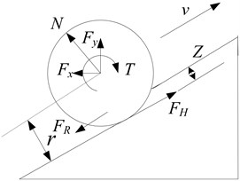
In order to research the wheel-soil interaction, a single wheel is well choosen. We assume that the entire wheel is stiff relative to the ground so that we can consider the wheel is rigid. Fig. 1 shows the forces and torques acting on the single wheel of a lunar rover [11]. Based on the terramechanics model, the contact forces and torques exerting on the wheels are calculated and optimized in this paper. In Fig. 1, , are the forces exerted on the wheel by rocker or bogie joint, is the normal force applied to the wheel, is the traction torque applied to the wheel, is the soil thrust acting on the wheel, is the motion-resistance force applied to the wheel, is the radius of the wheel, is the penetration depth. Assuming that is the static friction coefficient, is the dynamic friction coefficient. When the wheel purely rolls, the force acts on wheel is static friction force with the value is . When the wheel has a relative motion with the ground (with slip phenomenon), friction force becomes .
For each wheel, the net longitudinal force is the difference between the soil thrust and the motion-resistance force . The maximum net longitudinal force can be calculated as follows:
For the motion-resistance force , which consists of the resistance of terrain and the compaction resistance , it can be calculated as follows:
As the traction forces given to the ground are limited by wheel and the adhesion condition of the ground under real conditions, should be meet at all times.
The rolling resistance torque or friction torque is as follows:
where is the radius of the wheel.
Fig. 1Forces and torques acting on a rigid wheel
2.2. Longitudinal dynamics model
The rover is prone to slip when traverses over soft or challenging terrain. If the differences among slip ratios of each wheel are too large, the power consumption will increase and dangerous situations occurring. So it is necessary to coordinate and reduce each wheel’s slip ratio, and can effectively improve the obstacle-climbing capability and mobility. The slip ratio is defined as follows:
where is the angular speed of wheel, is the traveling velocity of wheel center.
In this definition, the value of is between –1 and 1. When the wheel speed is greater than the velocity of wheel center , is positive. Conversely, when the wheel speed is less than the velocity of wheel center , is negative. When is zero, wheels roll purely.
The following dynamical equations can be listed from the force analysis [12] for the rover model (bilateral symmetry) only considering the motion of longitudinal direction:
where , is the mass of the whole body, is the soil thrust of the wheel , is the motion-resistance force of the wheel , is the wheel inertia, is the wheel traction torque of wheel , is the rolling resistance torque of wheel .
Bring the Eq. (5) and (6) into the derivation of the Eq. (4), we can obtain the following equation:
where:
2.3. Trajectory tracking control model
Six wheeled lunar rover with rocker bogie consists of six driven wheels (front and rear four wheels with steering function), suspension system and body. Lunar rover is driven by the same mechanism with left and right independent. We combine differential steering with independent steering to achieve steering of lunar rover. The longitudinal slip is considered when discussing the rover kinematics. Assumptions are made as follows: 1, the lunar rover is all rigid without any flexible body involving. 2, steering axis of each steering wheel is perpendicular to the ground. 3, the orientation error generated during the vehicle driving is minor.
Fig. 2The diagram between kinematics path and lunar rover
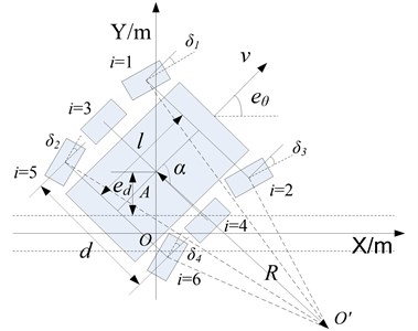
A coordinate system based on path is established as shown in Fig. 2. The centroid position of the rover is ; the orientation error is the angle between forward direction of lunar rover and the positive axis; the speed error is the velocity difference between left and right wheel; the lateral error is the coordinate of centroid point in the coordinate system.
The angles of each steering wheel are calculated as follows for a specified turning radius :
where is the front and rear wheelbase, is the width of the body, is the instantaneous turning radius of body movement, is steering azimuth, , , , are left front, left rear, right front and right rear wheel steering angle respectively.
According to the above four equations, steering angles of each steering wheel can be calculated when tracking a trajectory with fixed radius. At the beginning of tracking trajectory, the angles of each steering wheel should be adjusted to the corresponding values. During the process of tracking, the errors will inevitably occur because of the rough terrain. In order to protect the mechanism to avoid damage by frequent swing of steering wheels, we can achieve fine-tune of the orientation error and lateral error by means of left and right wheel differential steering when the desired curvature is constant, then the kinematics model of lunar rover can be achieved as shown in follows:
where and are the left and right average speeds of lunar rover respectively. is assumed to be minor, so .
The torque is chosen as input signal, while the output signal is the acceleration of wheel. Based on least squares method, the driven system can be identified and the transfer function is as follows:
From Eqs. (12), (13) and (14), the state-space of trajectory tracking control model can be derived:
where is state variable, is the system input (input torque ). The state equation is:
where , .
3. The trajectory tracking control algorithm based on slip compensation
3.1. Design of traction coordinating controller
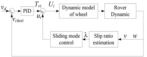
The traction coordinating controller designed in this paper is shown in Fig. 3, where is the desired speed (about 200 m/h), is the actual speed. We can regulate the lunar rover to track the desired speed by inputting the difference between and to the PID controller, also the total demand torque can be calculated. The torque should be allocated to the six wheels reasonably. The maximum traction force a terrain can bear increases with increasing normal force, so we set the coefficient (1-6, 1) to make up the disadvantage that sliding mode controller neglects the influence of normal forces on the traction torque. which meets the equation is the torque applied to wheel . The ratios of to the normal force of every wheel are equal, the greater normal force, the greater traction torque exerted on the wheel, thereby the traction force a terrain can bear increases to enhance the driving efficiency. Then adjusting the with the control output of sliding mode controller, to control the slip ratio of every wheel and gain the output of traction coordinating control.
The slip ratio of each wheel can be controlled effectively using the traction coordinating controller on the basis of controlling the velocity of lunar rover, which can reduce the force consumption, enhance the trafficability and improve the traction coordinating performance. According to the nonlinear characteristics of the longitudinal dynamics model of lunar rover, it is suitable to select the improved sliding mode controller to control the slip ratio. Taking the average slip ratio as the control target with using the improved approach law. Assuming the state error is , the switching function is as follows:
Fig. 3Diagram of traction coordinating control system
If the desired sliding mode control is achieved, the equivalent control method is defined as , combining Eq. (7) and results in:
In order to meet the reaching conditions of sliding mode control, reach the sliding surface in the shortest time and ensure that the system has good robustness, while trying to weaken the chattering, this paper adopts the improved exponential approach law [13, 14]:
where is the sign function. Substitution the derivation of Eq. (7) into Eq. (18) gives:
Combining Eq. (19) and (20), we obtain designing result of controller as follows:
where and are both weight coefficients, 0 and 0 are the control parameters. In order to ensure reduced buffeting and quickly approaching, should be reduced while increasing the value of , and the sign function also should be replaced by the saturation function. As:
The proposed law meets the reaching condition () of the sliding mode control. Then, the entire movement of the system is asymptotic stability.
3.2. The design of trajectory tracking controller
Under the precondition of wheels’ traction coordinating control, the corresponding trajectory tracking controller should be designed to track the desired trajectory of the lunar rover. The optimal control algorithm can be used to achieve trajectory tracking because the open-loop system of Eq. (16) is observability and controllability [15, 16].
The rover system can be regarded as a linear system proximately under the certain constraint condition. So the optimal problem of this system is quadratic optimal control problem with a purpose of seeking an optimal control signal , to make the evaluation index function minimum:
where and are both weighted matrices.
The optimal state feedback array can be obtained by solving the Riccati algebraic equation. That is to say:
is the control quantity of trajectory tracking, , , , are both state reaction coefficients.
The control quantity of trajectory tracking should be exerted on each wheel on the basis of traction coordinating control to correct the lateral error and the orientation error, a deviation-rectifying torque is added or subtracted to the control quantity of sliding mode traction coordinating control for each wheel in this paper. The deviation-rectifying quantities of four wheels (wheel 1, 2, 5, 6) are exerted according to the following proportion. Taking the turning for example, we assume is the turning radius, the rover moving around the turning center in a clockwise direction, as shown in Fig. 2. The torque of each wheel except the four turning wheels’ angles is divided as follows:
where:
and is the turning radius of lunar rover, is the width of lunar rover, is the length of lunar rover.
Based on the above theory, the trajectory tracking control is achieved considering the wheel slip in this paper, namely the trajectory tracking control algorithm with slip compensation. The control block diagram of the proposed algorithm is shown in Fig. 4.
4. Simulation analysis
Based on the dynamic calculation for multi-body system dynamics, ADAMS can do the static, kinematics and dynamics analysis on the complex mechanical systems and meet the requirements of lunar rover’s dynamics and kinematics model. The powerful control and mathematical operation function of MATLAB/Simulink not only can design and adjust the controller conveniently, but also simulates the mechanical properties of soft soils to make up for the simulation deficiency for ADAMS on soft surface. The combination of ADAMS and MATLAB/Simulink makes the simulation of lunar rover’s coordinating control with high accuracy come true. Therefore, the 3D simulation model of six-wheeled lunar rover with rocker bogie is established using the multi-body kinematics and dynamics analysis software-ADAMS in this paper, as shown in Fig. 5.
Fig. 4Block diagram of the proposed control algorithm
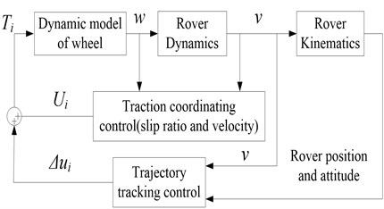
Fig. 53D simulation model and simulation environment of trajectory tracking algorithm based on the slip compensation (1 – body; 2 – cross-bar; 3 – bogie; 4 – wheel; 5 – rocker)
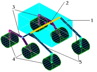
The parameters of lunar rover are as follows: the total mass of the prototype is 120 kg. The mass of single wheel is 7 kg. The wheel diameter is 240 mm. The width of the wheel is 200 mm. The external dimensions are: 800 mm×500 mm×350 mm.
There are two parameters in the transfer function of the driven system (shown in Eq. (14), 20, 3.5), they are obtained by identifying the simulation model. Choosing and in Eq. (22) as identity matrices, then the state feedback array of the optimal control law can be calculated as [0.3442 5.3419 1.0000 1.1389].
Two sets of simulations are performed in order to validate the proposed control algorithm: climbing a slope and curved line trajectory tracking simulation.
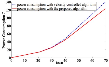
In the first simulation, the lunar rover is commanded to traverse a slope with a velocity of 200 m/h. Fig. 6 shows the slip ratio curves of unilateral three wheels with only velocity-controlled algorithm. Fig. 7 shows the slip ratio curves of unilateral three wheels with traction coordinating control algorithm, the slip ratios of three wheels are almost the same, eventually stabilized at 35 %. For most soils the maximum traction force the soil can support increases with the increasing normal force, while the normal force of front wheel is relatively small, so the maximum traction force of front wheel is relatively smaller than rear and middle wheels. The overlarge traction torque of front wheel caused by the overlarge slip ratio can be minimized by reaching the unanimity of slip ratios (Fig. 7), which prevented the soil from damage. Meanwhile, the traction torques of rear and middle wheel can be increased appropriately to enhance the utilization of friction force and the climbing ability. Fig. 8 shows the total power consumption of two algorithms.
Fig. 6Slip ratio curves of three wheels with only velocity-controlled algorithm
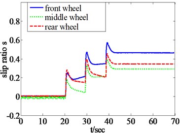
Fig. 7Slip ratio curves of three wheels with the traction coordinating control algorithm
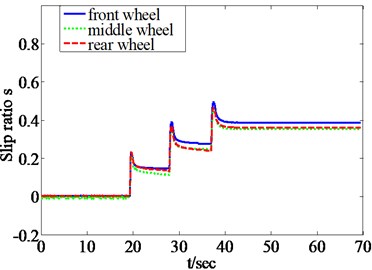
Fig. 8Power consumption comparison of two algorithms
The evaluation indexes of trafficability in vehicular field are traction coefficient and tractive efficiency. Traction coefficient , tractive efficiency:
Table 1 gives the trafficability indexes comparison between only-velocity control and traction coordinating control, from which we can see that the two indexes are both enhanced to different level after using the traction coordinating controller.
Table 1Trafficability indexes comparison of two control algorithms
Trafficability evaluation indexes | Only-velocity control | Traction coordinating control |
Traction coefficient TC | 0.6127 | 0.6534 |
Tractive efficiency TE | 0.3342 | 0.3665 |
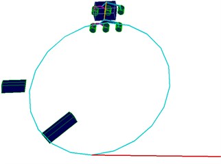
In addition, a complicated simulation working condition is built taking circles and straight lines as the desired trajectory with hump obstacles (Fig. 5). Fig. 9 shows the trajectory tracking results comparison between with and without slip compensation. The proposed algorithm can efficiently control the rover traveling along the desired trajectory from the correlation curves between the desired trajectory and real trajectory. The trajectory tracking control algorithms with and without slip compensation under the working condition of tracking circle trajectory and climbing one-side obstacles, as shown in Fig. 5, are compared to prove the validity of slip compensation. Fig. 10 shows the slip ratio correlation curves of unilateral (left) three wheels using trajectory tracking control algorithm with or without slip compensation. The extreme values of slip ratio is up to 0.5 and –1 controlled without slip compensation, while the slip ratio can be controlled within –0.3 and 0.4 after compensating the slip ratio.
Fig. 9Trajectory tracking control curves comparison between with and without slip compensation
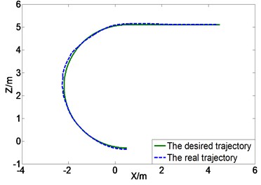
Fig. 10Slip ratio curves of three left wheels comparison between with and without slip compensation
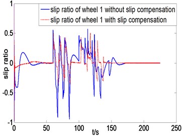
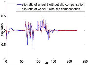
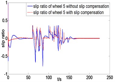
Fig. 11The lateral error and orientation error when following a straight line
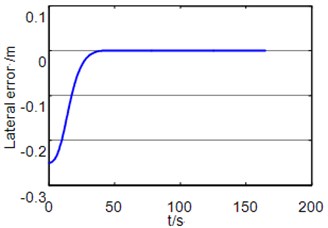
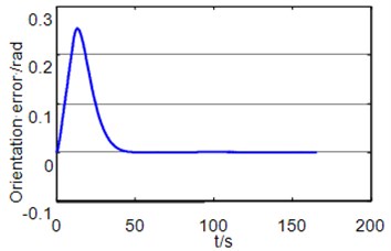
To analysis the tracking errors of the trajectory tracking control method, a straight line tracking simulation with original lateral error has been performed. In the initial state, the lateral error is set to 0.25 m, and the Rover’s speed is set to 200 m/h. From Fig. 11, we can see that the orientation error and lateral error can all converge to zero.
The simulation results indicate that the proposed control algorithm can efficiently control the slip ratio while ensuring the tracking accuracy, reduce the power consumption, enhance traction coordinating performance and then improve the trafficability and mobility of the rover under complex environment.
5. Conclusions
In this paper, a trajectory tracking and traction coordinating controller has been presented based on the kinematics and dynamics analysis. The effectiveness of the proposed algorithm is validated by the co-simulation of ADAMS and MATLAB/Simulink. Simulation results demonstrate that based on the premise of tracking accuracy, the slip ratios can be controlled within a proper scope, the power consumption can be reduced, improvement of trafficability and then reducing the mechanical wear and increasing the service life.
References
-
Iagnemma K., Ward C. C. Classification-based wheel slip detection and detector fusion for mobile robots on outdoor terrain. Autonomous Robots, Vol. 26, Issue 1, 2009, p. 33-46.
-
Ward C. C., Iagnemma K. A dynamic model-based wheel slip detector for mobile robots on outdoor terrain. IEEE Transactions on Robotics, Vol. 24, Issue 4, 2008, p. 821-831.
-
Iagnemma K., Dubowsky S. Traction control of wheeled robotic vehicles in rough terrain with application to planetary rovers. The International Journal of Robotics Research, Vol. 23, Issue 10-11, 2004, p. 1029-1040.
-
Lamon P., Krebs A., Lauria M., Shooter S., Siegwart R. Wheel torque control in rough terrain modeling and simulation. Proceedings of the IEEE International Conference on Robotics and Automation, Barcelona, Spain, 2005.
-
Ishigami G., Nagatani K., Yoshida K. Path planning for planetary exploration rovers and its evaluation based on wheel slip dynamics. IEEE International Conference on Robotics and Automation, 2007, p. 2361-2366.
-
Mongkol Thianwiboon, Viboon Sangveraphunsiri Traction control of a rocker-bogie field mobile robot. Thammasat International Journal of Science and Technology, Vol. 10, Issue 4, 2005, p. 48-59.
-
Lhomme-Desages D., Grand C., Amar F. B., Guinot J. C. Dopper-based ground speed sensor fusion and slip control for a wheeled rover. Transaction on Mechatronics, Vol. 14, Issue 4, 2009, p. 484-492.
-
Rezaei S., Guivant J., Nebot E. M. Car-like Robot path following in large unstructured environments. Proceedings of the International Conference on Intelligent Robots and Systems, Las Vegas, NV, 2003.
-
Helmick D. M., et al. Path following using visual odometory for a mars rover in high-slip environments. Proceedings of the Aerospace Conference, Big Sky, MT, 2004.
-
Ishigami G., Yoshida K. Slope traversal experiments with slip compensation control for lunar/planetary exploration rover. Proceedings of the International Conference on Robotics and Automation, Pasadena, CA, 2008.
-
Deng Zong-quan, Zhang Peng, Gao Haibo Configuration synthesis and performance evaluation metrics of lunar rover locomotion systems. Transactions of Tianjin University, Vol. 15, Issue 3, 2009, p. 193-200.
-
Gu Kan-feng, Zhao Ming-yang Dynamic modeling and simulation of driving control for wheeled mobile robot on sand. Journal of System Simulation, Vol. 20, Issue 18, 2008, p. 5035-5039.
-
Mao Yan-e, Jing Yuan-wei, Zhang Si-ying, et al. On variable structure control with sliding mode for automotive anti-lock braking systems. Journal of System Simulation, Vol. 20, Issue 5, 2008, p. 1243-1245.
-
Zhong Rong-duan, Guo Yong-huang, Zong Kai-shao, et al. Integral sliding mode control based on exponential approach law for brushless double fed machines. Applied Mechanics and Materials, Vol. 454, 2013, p. 48-52.
-
Solea R., Nunes U. Trajectory planning and sliding-mode control based trajectory-tracking for cybercars. Integrated Computer-aided Engineering, Vol. 14, Issue 1, p. 2007, p. 33-47.
-
Rossomando F. G., Soria C., Carelli R. Sliding mode neuro adaptive control in trajectory tracking for mobile robots. Journal of Intelligent and Robotic Systems, 2013.
About this article

This project is supported by the National Natural Science Foundation of China (Grant No. 51107006, 61203171, 61473057), China Postdoctoral Science Foundation (Grant No. 2012M510799, 2013T60278).
