Abstract
This paper introduces the shock response spectrum for the spacecraft unit using electromagnetic shaker, and analyzes the problems and shortages of it. In addition, the paper introduces the improvement of the shock response spectrum for spacecraft unit using electromagnetic shaker. The improved test method is more stable in control results and more convenient to pretest than before, which improves the productive efficiency. Practice has shown that the method is feasible.
1. Introduction
The shock environment occurs in the spacecraft as a result of the workings of all kinds of equipment pyrotechnic devices used on spacecraft. The equipment pyrotechnic devices will fulfill certain tasks in the course of the launch of the spacecraft (including separating the spacecraft and the launch vehicle, separating both module and disconnecting deployment for spacecraft solar wing, etc.) [1]. There are various equipment pyrotechnic devices used on spacecraft, such as explosive bolts, separation nuts, bolt and cable cutters and V-band clamps. This kind of shock environment is referred to as a “pyroshock”. Pyroshocks are generally within a frequency range between 100 Hz and 1,000,000 Hz, and time duration from 20 microseconds to not more than 20 milliseconds. Acceleration response amplitudes to pyroshock may range from 300 g to 300,000 g [2-6]. In general, pyroshocks generate material stress waves that will excite materiel to respond to very high frequencies with wavelengths to spacecraft unit, and will cause damages to the unit so that some spacecraft task cannot be fulfilled. It is particularly important, therefore, to do the shock response spectrum (SRS) for the spacecraft unit [7].
So far, the shock response spectrum test for the spacecraft unit is realized by two ways, i.e. mechanical shock machine and electromagnetic shaker. Of the two, the latter is better than the former because the electro-dynamic shaker ensures stability, controllability and uniformity. Meanwhile, it can complete the positive and negative direction but has to be fixed once for the spacecraft unit. Above all, the electromagnetic shaker is preferred to do the shock response spectrum tests in the capacity of equipment.
2. Problems and shortages of SRS using electromagnetic shaker
2.1. Test methods of SRS using electromagnetic shaker
The test system of SRS using electromagnetic shaker consists of three parts, i.e. electromagnetic shaker system, control system and assemblage of a spacecraft unit (or a calibration load) and fixture. The electromagnetic shaker system is composed of electromagnetic shaker, horizontal sliding table, power amplifier and accessory equipment. The control system includes computer, controller, acceleration transducers and signal conditioning.
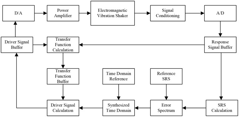
Before the SRS test is done, an appropriate set of waveform is selected by professional SRS software and is synthesized a SRS for 10 and at least at 1/6-octave frequency intervals. Then the waveform is converted into the driver spectrum via the controller. The driver spectrum is transmitted to the power amplifier via A/D. The power amplifier drives the electromagnetic shaker to produce a shock signal. Then the shock signal is transmitted to the controller via acceleration transducers, signal conditioning and A/D, and is synthesized a new SRS. An error spectrum of the new SRS and the reference SRS is obtained. The controller corrects the driver spectrum. The above steps are repeated, until there is not significantly different between the synthesized SRS and the reference SRS [1]. The principle of SRS using electromagnetic shaker is shown in Fig. 1.
Fig. 1Principle of SRS using electromagnetic shaker
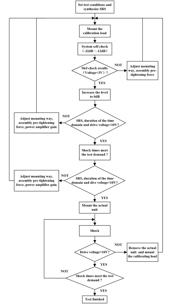
So far, the specific implementation process of the SRS using electromagnetic shaker for the spacecraft unit is divided into three parts:
a) Set test conditions and synthesize SRS. According to the task book requirement, an appropriate set of waveform should be selected first. If necessary, the delay of the time domain waveform will be adjusted. Then the waveform is synthesized the SRS. Assure that test requirements (force, acceleration, velocity and displacement) are met. If not, another new set of waveform must be selected and adjusted.
b) Mount the calibration load and perform calibration shock. The synthesized SRS is reduced to some a level (normally –32 dB). This signal is transmitted to the electromagnetic shaker system. Then the shock signal is transmitted to the controller and an error spectrum is obtained and corrects the driver spectrum. It will rise to a new level and the above steps are repeated until to 0 dB level.
c) Repeat shocks until two consecutive shock applications to the calibration load produce shock transients that are within specified test tolerances for at least one direction of one axis. Then remove the calibrating load and mount the actual unit on the Electromagnetic shaker. The actual shock test starts.
Structure of the SRS using electromagnetic shaker is shown in Fig. 2.
2.2. Problems and shortages of SRS using electromagnetic shaker
a) Complex pretest process and long period of pretest the calibration load.
The data acquisition board of the controller is generally within a voltage range between –10 V and +10 V. When the drive voltage is out of range of the voltage, the controller must be stopped and the system needs a self-check. Moreover, even if it remains within the range while the level of the SRS rises to 0 dB, the controller must be stopped because the high frequency range of the SRS (from 1500 Hz to 4000 Hz) is over-ranged signal conditioning. Therefore, the pretest process becomes complex and the period of pretest the calibration load is very long. Meanwhile the repeated shock will make the moving coil of the electromagnetic shaker crack and affect the useful life of the electromagnetic shaker.
b) Repeat shocks until the drive voltage between +10 V and –10 V.
The drive voltage of the controller increases with the increasing level of the SRS through all this shock. When doing less small magnitude (under 600 g) and less shock on the number, it is not much impact on the shock test procedure due to the low drive voltage (usually 8 V or less). However, when the larger magnitude and more shock time, then the driving voltage is generally above 8 V, even close to 10 V. With the increase in the number of shocks, the drive voltage will exceed the range of ±10 V. At this time, the test must be stopped, the actual unit must be removed and the calibrating load should be amounted before restarting the pretest. Therefore, the efficiency of test is very low.
Fig. 2Structure of the SRS using electromagnetic shaker before improvement
3. Improvement of SRS using electromagnetic shaker
3.1. Improvement of test methods of SRS using electromagnetic shaker
Throughout the course of the SRS test, the control system is always in closed-loop control state, but the long-term shock experience has shown that with the increase in the number of shock, the drive voltage increases slowly and the level of the SRS also increases in the entire frequency band, even if the status of assembly pre-tightening, installation and power amplifier gain remain unchanged. In view of this, a new test method is as follows.
Fig. 3Structure of the SRS using electromagnetic shaker after improvement
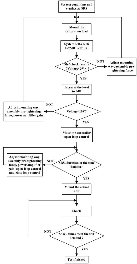
a) Make the control system in open-loop control state after reaching the full level (0 dB).
Before the system self-check and reaching the full level (0 dB), the control system adopts closed- loop control in order to ensure the system to correct the driver spectrum so that the shock test meets the test requirements (the frequency domain and the time domain) as much as possible after reaching the full level (0 dB). Then make the control system in open-loop control state, and adjust the SRS by changing the installation way, assembly pre-tightening force, installation and power amplifier gain etc.
b) Adjust the SRS with open-loop and closed-loop control.
Considering the closed-loop control characteristics that with the increase in the number of shock, the level of the SRS is increased in the entire frequency band, the SRS can be adjusted by making the control system in closed-loop control when the SRS of the whole frequency band is under the test conditions and the drive voltage is low (usually under 9 V) until it meets the test requirements, then keep the control system in open-loop control state.
On the other hand, when the control system is in open-loop control state, the adjustment of the high frequency range (from 1500 Hz to 4000 Hz) that is out of tolerance has more obvious effect by changing the installation way, assembly pre-tightening force, installation and power amplifier gain etc.
Structure of the SRS using electromagnetic shaker after improvement is shown in Fig. 3.
3.2. Attention and solutions to common problems of improved SRS
a) How to adjust, when the SRS is over-ranged signal conditioning.
The solutions of the high frequency range (from 1500 Hz to 4000 Hz) that is out of tolerance in the process of open-loop control include: increasing the number of bolts, increasing the assembly pre-tightening force, reduced power amplifier gain. The suitable way to adjust need be selected according to the SRS, the shaker, the fixture, installation way and even the various methods mentioned above. If the problem still cannot be solved, the acceleration transducer position needs to be changed, and a self-check should be conducted until the test requirements are met.
b) How to adjust, when the SRS cannot meet requirement that at least 50 percent of the SRS magnitudes exceed the nominal test specification.
When the SRS cannot meet the requirement that at least 50 percent of the SRS magnitudes exceed the nominal test specification, the following steps shall be taken: first, when the SRS of the whole frequency band is under the test conditions and the drive voltage is low, increase the level (e.g. +0.5 dB level); second, make the control system in closed-loop control state, the drive voltage is corrected; third, when the concave high frequency, adjust the SRS by decreasing the number of bolts, decreasing the assembly pre-tightening force, and increasing the power amplifier gain. If the problem still cannot be solved, the acceleration transducer position needs to be changed, and a self-check shall be conducted until the test requirements are met.
Table 1Comparison with test results
Product name | Test conditions | Shock times | Quantity | Total shock times | Pretest times | |
Before improvement | Explosive Bolts II | 100 Hz~700 Hz +8 dB/oct 700 Hz-3000 Hz 1200 g | Three times in each direction of all three axes | 21 | 189 | 46 |
After improvement | Explosive Bolts | 100 Hz~700 Hz +8 dB/oct 700 Hz~-3000 Hz 1500 g | Three times in each direction of all three axes | 21 | 189 | 16 |
4. Comparison with test results
The improved method applied in 50 kN electromagnetic shaker proves that the control effect is more stable than before. In addition, this method also reduces the number of pretesting that means reducing the damage to the moving of the electromagnetic shaker. This method has a more obvious effect on the mass product test. Table 1 is the state of the plant in Shenyang explosive bolts shock test contrast before and after improvement.
As can be seen from the table, by using the improved test method, the pretest times is from 46 down to 16, the pretest number decreased by 2.875 times.
5. Conclusions
In this paper, the shortages are also pointed out and improvement views are put forward about the current SRS test for the spacecraft unit using the electromagnetic shaker. The test improved method makes the control of the SRS more effective and more stable, with better repeatability. At the same time, it reduces the number of pretests, as this method has a more obvious effect on the mass product test. A lot of experiments have proved that the improved test method is more effective.
References
-
Ke Shouquan Spacecraft Environment Engineering and Simulation Test. Beijing, Aerospace Press, 1996.
-
GJB 150.18A-2009, Laboratory environmental test methods for military materiel-Part 18: Shock test, 2009.
-
GJB 150.27-2009, Laboratory environmental test methods for military materiel-Part 27: Pyroshock test, 2009.
-
MIL-STD-1540D, Product verification requirements for launch, upper stage, and space vehicles, 1999.
-
MIL-STD-810F, Environmental engineering considerations and laboratory tests, 2000.
-
MSFC-DOC-2042-93, Advanced solid rocket booster vibration, acoustic and shock design and test criteria, 1993.
-
Wang Zhaoxia, Wang Jian, Fan Shichao Application of a vibration system in shock response spectrum test. Spacecraft Environment Engineering, Vol. 2, 2009, p. 137-139.
About this article

