Abstract
In this work, the dynamic characteristics of the human head-neck system under vibration are studied. For the purpose of our analysis, we adopted a detailed finite element model of the human head-neck, which includes the facial and intracranial details such as the subarachnoid space. The finite element method has allowed us to identify the mechanical properties of the head-neck and to validate a mathematical model in the frequency domain. The extracted modal characteristics consist of a first natural frequency at 34.43±0.1 Hz associated with the head-neck anterior-posterior extension-flexion mode and a second mode at 57.59±0.5 Hz associated with the lateral flexion mode of the head-neck. The results are in agreement with other researchers’ analogous modelling work, however, our three-dimensional analysis introduces additional reported modal responses to the natural frequencies spectra of the head-neck system. The results are compared with experimental ones and the role of damping factor on the natural frequencies is investigated. This study provides new insight into injury mechanisms when a given natural frequency can be linked to a specific head-neck deformation.
1. Introduction
The human head, when subjected to mechanical vibration either by action of an acoustic field or by contact with vibrating structures, responds by vibrating in certain modes with an intensity of depending on its anatomical peculiarities [1]. Investigation and explanation of its responses are problems in their own, and the knowledge of why and how it vibrates will contribute to a general understanding of human body mechanics. This may aid in development of a protective headgear in both civilian and military contexts [2].
Previous research on human head vibration was mainly based on experimental tests involving cadavers, animals and volunteer living subjects. Both Hodgson et al. [3] and Gurdjian et al. [4] reported that the resonant frequency of a cadaver head in their mechanical impedance analysis was approximately 300 Hz. V. Bekesy [5] investigated the vibration response of a cadaver skull in an acoustic field and reported that the first resonant frequency of the skull to be 1800 Hz. The experimental modal study, performed by Franke [1] on both an empty dry human skull and the same skull filled with gelatin, found that the lowest resonant frequencies were 800 Hz and 500 Hz respectively. At the same time, Hakansson et al. [6]’s in vivo study utilizing skin penetrating titanium implants on patients’ temporal bone claimed that the lowest undamped natural frequency were about 972 Hz. Khalil et al. [7] conducted an experimental study on two cadaver heads using an impact hammer. The respective fundamental frequencies found were 1385 Hz and 1641 Hz. Stalnaker and Fogle [8] utilized an electromagnetic shaker in their experimental tests of a fresh unembalmed cadaver head and determined that the resonant frequencies were 166 and 820 Hz. In contrast, experimental studies on living human subjects showed the resonant frequency arranged from a few Hz to 300 Hz [3, 5, 9-11]. Despite the bulk of valuable information provided by experimental data, these tests do not only raise issues in morality and ethics, but also induce many research concerns such as limited flexibility in experimental data due to scarce subjects and non-standardized experimental procedures.
These earlier FE studies had undoubtedly provided some insights in the dynamic characteristics of the human head. Nonetheless, they had made numerous simplifications in the geometry of the head. In the present work, a detailed FE model of human head and neck has been developed and its modal responses have been determined. In addition, the simulated modal responses in terms of resonant frequencies and mode shapes are compared with those in literature, unlike most previous studies which only compared their resonant frequencies and ignored modal validation in terms of mode shapes. Furthermore, this paper also investigates the effect of damping on dynamic characteristics.
2. Methods and materials
2.1. Finite element method and governing equation
In order to determining modal responses, modal analysis using finite element method (FEM) is performed using an implicit finite element code (Abaqus). The problem analyzed is that of looking for eigenvalues and eigenvectors of the rigidity and mass matrices of the model. After system discretization by finite elements, the equation governing the dynamic response is given as follows:
where , and are the global mass, damping and stiffness matrices of the model; , , and are the nodal acceleration, velocity and displacement vectors; represents the sum of the external loads applied to the structure.
For undamped free vibration (i.e. ), the solution of the above equation can be written as follows:
where represents the amplitudes of all the masses (mode shapes or eigenvectors) and represents each eigenvector’s corresponding eigenfrequency in rad/s, while represents the natural frequency in hertz. Thus Eq. (1) reduces to:
The above equation is known as eigenvalue problem in matrix algebra and is considered as linear by replacing by . The system solution, which relies on determining each eigenvector , with its corresponding eigenvalues , is solved by the natural frequency extraction using Lanczos eigensolver [12].
For the case of damped free vibration (i.e. ), the eigenvalue equation is quadratic as it contains an additional term of :
The complex eigenvalue problem is solved by the complex eigenvalue extraction procedure using a projection method [12]. In this present study, four global material damping factors of 0.1, 0.2, 0.3 and 0.4, which are within the range of damping factors of head and neck found in the literature [7, 9, 10, 13], are included in this complex eigenvalue analysis of the multi-degree of freedom problem. In addition, the biomechanical parameters such as skull stresses and intracranial pressure (ICP) are evaluated at each individual mode for both damped and undamped cases. It shall be noted that the stresses evaluated are not due to any external applied force, in fact, they are element stresses which are computed based on the following equation in FEM [14]:
where is the constitutive matrix of the element; is the elemental strain.
2.2. Mesh development and interface conditions
A male volunteer with anthropometric characteristics close to the 50th percentile Singapore Chinese male was recruited to develop an extensive image data set. The resolution/thickness of the computed tomography (CT) and magnetic resonance imaging (MRI) scans were 0.488/1.0 mm and 0.500/4.0 mm, respectively. The geometries of the bony structures and soft tissues of the volunteer head region were reconstructed using the CT and MRI scanned images, using the segmentation method developed by Dale et al. [15] and later on by Fischl et al. [16]. With minimum manual edition, we sought to align the MRI to the CT, and registration accuracy was evaluated by performing analysis of the coordinate differences between CT and MR anatomical landmarks along the -, - and -axes. The human brain was segmented into cerebellum, gray and white matters, the entire ventricular system of the brain.
Despite recent advancements in segmentation methods for brain tissue with Magnetic Resonance Images (MRI) [17], there is no automatic segmentation tool available for non-brain tissues such as extracranial tissues like cartilages, fats, and neck muscles. This was owing to the fact that segmentation of these tissue types was often ignored since these tissues were regarded as less important as compared the skull-brain tissue and were not usually considered in the FE head model. Based on the reference to available atlas of head anatomy [18], the geometry of the cartilages, namely the cartilage of septum, the lower and upper lateral cartilages of the human nose, are reconstructed semi-automatically using an adaptive moving mesh technique and shape preserving parameterization.
Multi-tissue mesh generation on medical images is a fundamental step for building a realistic biomechanical model. Mesh elements with large or low dihedral angles are undesirable. In the literatures, there have been studies on multi-tissue meshing based on Delaunay refinement [19, 20].However, elements with small dihedral angles are likely to occur in Delaunay meshes, because elements can be removed only when their radius-edge ratio is large.
Fig. 1Fixed boundary condition is applied at the surface nodes of the base of the neck
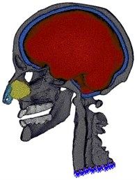
Unlike above Delaunay-based methods, Zhang et al. [21] presented a new method to generate a hexahedral and tetrahedral mesh. Firstly, this method identified the interface between different tissues and non-manifold nodes on the boundary. Then, all tissue regions were meshed with conforming boundaries cooperatively. Finally, geometric flow schemes and edge-contraction were used to improve the quality of the hexahedral mesh. In our work, we incorporated mesh quality, fidelity and smoothing into one point based registration framework. The existing hexahedral meshes were optimized on combining Laplacian and optimization-based mesh smoothing, nodal points deletion and insertion as well as local remeshing. The resulting meshed head model is composed of 403, 176 hexahedral elements and 483, 711 nodes (Fig. 1).
The surface nodes at the base of the head-neck model are constrained in all the six degrees of freedom (Fig. 1) while all the interfaces between components are prescribed with tie conditions since interaction properties are not available in modal analyses.
3. Results
This section presents result on the dynamic characteristics (resonant frequencies and mode shapes) of the 3D FE model of human head-neck. By performing modal analysis on the 3D FE head-neck system based on Abaqus 6.10 software, twenty-five resonant frequencies and associated mode shapes are recognized in the frequency band of 35 to 360 Hz (Fig. 2). These computed resonant frequencies in the undamped and damped free vibrations are tabulated, with their respective first resonant frequencies at 35.57 Hz, 34.59 Hz, 34.43 Hz and 33.78 Hz. Fig. 3 shows five various, distinguishable mode shapes of the head-neck complex: an anterior-posterior extension-flexion mode of the head about the neck at 35.57 Hz, a lateral flexion mode at 62.89 Hz, a S-shaped anterior-posterior retraction mode of the head and neck at 221.51 Hz, an axial rotational mode of the head about its vertical axis at 72.40 Hz and finally a vertical translational mode of the head at 254.04 Hz. Also, the lateral flexion of the nasal lateral cartilages as well as the lateral translation of the mandible, which dominate after the primary modes of the head-neck structure within its first twenty-five modes, are identified (Figs. 3-5). The mode shapes for the damped vibration cases are identical to that of the undamped vibration, except for the difference in the arbitrary magnitude of biomechanical parameters such as displacement and skull Mises stresses.
4. Discussion
4.1. Comparison of fundamental frequency
In the present work, Meyer et al. [22]’s FE study is chosen for comparison of the modal responses as it is the only study involving the head-neck system which is similar to the present FE model. Our computed fundamental frequency in the free vibration is 35.57 Hz while Meyer et al. [22] reported that the fundamental frequency is 3.01 Hz. This discrepancy in the fundamental frequency arises between the two FE models, probably due to the difference in the way in modeling and material properties, with the former factor being more likely to contribute to the discrepancy. With the prioritized focus on the neck injury, the head and all the cervical vertebrae of Meyer et al. [22]’s FE model were modeled as rigid bodies, with all the individuals’ masses and inertial moment taken into account. Only the intervertebral discs were modeled as deformable bodies. On the contrary, all the components in our FE head-neck model are modeled as deformable bodies with the ability to dissipate external energy through deformation. In addition, unlike the rigid head of Meyer et al. [22]’s FE model, our FE head model contains skull, subarachnoid space (including CSF and membranes), cartilages as well as brain tissues. By having the various distinct components in the head model, especially with the lumped mass of viscous intracranial content, the fundamental frequency of the multi-components system is expected to be lower than that of a one-component system as additional natural frequencies appear on the frequency spectrum of the one-component system. This phenomenon is consistent with observations by Guarino and Elger [23] and Chu et al. [24].
In summary, our computed fundamental frequency of 35.57 Hz is reasonably close to the reported range of 20 to 30 Hz in book reviews [25-27] and handbook [28]. Although the present value is lower than the few hundred hertz of the analytical skull-brain-neck system by Charalambopoulos et al. [2] and higher than the few hertz as predicted by Meyer et al. [22]’s FE study, it is still considered to fall within a reasonable range since the consensus on this dynamic characteristic remains debatable.
Fig. 2Mid-sagittal view of the displacement magnitude (in mm) contour plots of the head-neck model, showing various mode shapes and their corresponding frequencies for the undamped vibration case
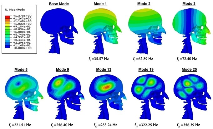
Fig. 3Comparison of the mode shapes with Meyer et al. [22]’s FE head-neck model
![Comparison of the mode shapes with Meyer et al. [22]’s FE head-neck model](https://static-01.extrica.com/articles/15341/15341-img3.jpg)
4.2. Comparison of mode shapes
Most of the previous studies compared their resonant frequencies with those found in the literature whilst modal comparison in terms of mode shapes was often ignored. A limited number of published works [7, 24] on the vibration patterns of the human head can be found in literature and some of them are unsuitable for comparing human head’s mode shapes. Khalil et al. [7]’s simplified representation of mode shapes in terms of stationary nodal lines were only indicated on the top and lateral sides of the skull, due to extremely complex geometry of the skull base and the facial region, whilst Chu et al. [24]’s modal analysis using a 2D FE skull-brain lacked detailed vibration patterns. To the best knowledge of the author, the only work that had recorded the detailed description of mode shapes of human head and neck, was the FE study by Meyer et al. [22]. In order to further validate our newly developed 3D FE model of head-neck, the simulated fundamental frequency is compared with those in the literature while the mode shapes obtained from the simulations are also compared with the mode shapes as predicted by Meyer et al. [22]’s FE head-neck model.
Fig. 4(Still Instance No. 1) Comparison of the mode shapes with Meyer et al. [22]’s FE head-neck model
![(Still Instance No. 1) Comparison of the mode shapes with Meyer et al. [22]’s FE head-neck model](https://static-01.extrica.com/articles/15341/15341-img4.jpg)
It is demonstrated in Fig. 3-5 that the first three mode shapes in our model are similar to that of Meyer et al. [22]’s FE model, which correspond to extension-flexion mode, lateral flexion mode as well as axial rotation mode of the head respectively. It is then followed by the fourth mode shape resembling the resonance of the mandible, which were not included in Meyer et al. [22]’s FE model. Our fifth mode shape matches well with the S-shaped anterior-posterior retraction mode found in Meyer et al. [22]’s fourth mode. However, the fifth mode shape of lateral retraction is not captured in the simulations of the present model. Instead, the eighth mode of the current study is considerably similar to the vertical translation mode (sixth mode) of the neck in Meyer et al. [22]’s model. The current model, with detailed facial features, is able to simulate or capture the additional modes of the lateral flexion of the nasal lateral cartilages and the “mastication” mode of the mandible which have never been shown in any vibration analysis. The presence of these additional modes also indicates the importance of detailed modeling in identifying all the resonant modes of the individual components.
Fig. 5(Still Instance No. 2) Comparison of the mode shapes with Meyer et al. [22]’s FE head-neck model
![(Still Instance No. 2) Comparison of the mode shapes with Meyer et al. [22]’s FE head-neck model](https://static-01.extrica.com/articles/15341/15341-img5.jpg)
5. Conclusions
1) The knowledge of how and why the modal responses of the human head change is very important in the study of head injury. This study employs both the traditional and the complex modal analyses of a detailed finite element (FE) model of human head-neck system. It is conducted with the goal of determining modal responses in terms of resonant frequencies and mode shapes as well as finding an explanation for huge variation in head’s resonant frequencies reported in literature.
2) Unlike most of the previous studies, this study compares both modal responses without ignoring modal validation in terms of mode shapes. These results are found to be within a reasonable range reported in literature. It is found that increasing displacement contour loops in the brain for higher frequency modes probably exhibit the shearing and twisting modes of the brain. Additional and rarely reported modal responses such as “mastication” mode of the mandible and flipping mode of nasal lateral cartilages are identified. This suggests a demand for detailed modeling to identify all the additional frequencies of each individual part.
3) The current study also investigates the effects of damping on both modal responses and biomechanical responses. It is found that a damping factor of above 0.2 has an amplifying effect in reducing higher mode frequencies, whilst diminishing effect in lowering peak biomechanical responses, indicating the importance of identifying the appropriate optimized damping factor.
References
-
Franke K. E. Response of the human skull to mechanical vibrations. Journal of the Acoustical Society of America, Vol. 28, 1956, p. 1277-1284.
-
Charalambopoulos A., Dassios G., Fotiadis D. I., Massalas C. V. Frequency spectrum of the human head-neck system. International Journal of Engineering Science, Vol. 35, Issue 8, 1997, p. 753-768.
-
Hodgson V., Gurdjian E., Thomas L. The determination of response characteristics of the head with emphasis on mechanical impedance techniques. 11th Stapp Car Crash Conference, 1967.
-
Gurdjian E. S., Hodgson V. R., Thomas L. M. Studies on mechanical impedance of the human skull: Preliminary report. Journal of Biomechanics, Vol. 3, Issue 3, 1970, p. 239-247.
-
Bekesy G. V. Vibration of the head in a sound field and its role in hearing by bone conduction. The Journal of the Acoustical Society of America, Vol. 20, Issue 6, 1948, p. 749-760.
-
Hakansson B., Brandt A., Carlsson P., Tjellstrom A. Resonance frequencies of the human skull in vivo. Journal of the Acoustical Society of America, Vol. 95, Issue 3, 1994, p. 1474-1481.
-
Khalil T. B., Viano D. C., Smith D. L. Experimental analysis of the vibrational characteristics of the human skull. Journal of Sound and Vibration, Vol. 63, Issue 3, 1979, p. 351-376.
-
Stalnaker R. L. Fogle J. L. Driving point impedance characteristics of the head. Journal of Biomechanics, Vol. 4, Issue 2, 1971, p. 127-139.
-
Willinger R., Bourdet N., Fischer R., Le Gall F. Modal analysis of the human neck in vivo as a criterion for crash test dummy evaluation. Journal of Sound and Vibration, Vol. 287, Issue 3, 2005, p. 405-431.
-
Rützel S., Hinz B., Wölfel H. P. Modal description-A better way of characterizing human vibration behavior. Journal of Sound and Vibration, Vol. 298, Issue 3, 2006, p. 810-823.
-
Tzeng H. S., Tseng S.W., Lee M. C. Modal testing of the human head. Proceedings of Annual Symposium on Biomedical Engineering Society, 1992, p. 313-316.
-
Abaqus. Abaqus Analysis User’s Manual. Version: 6.10, Dassault Systèmes Simulia Corp., 2010.
-
Whitman T. A., Wodicka G. R., Morgan M. T., Bourland J. D. Measurement and modeling of the vibrational response of the ovine head as it relates to intracranial pressure. Proceedings of Engineering in Medicine and Biology Society, Bridging Disciplines for Biomedicine, Proceedings of the 18th Annual International Conference of the IEEE, Vol. 492, 1996, p. 493-494.
-
Zienkiewicz O., Taylor R., Zhu J. The Finite Element Method: Its Basis and Fundamentals. Sixth Edition, Elsevier Butterworth-Heinemann, Oxford, 2005.
-
Dale A. M., Fischl B., Sereno M. I. Cortical surface-based analysis. I. Segmentation and surface reconstruction. Neuroimage, Vol. 9, Issue 2, 1999, p. 179-194.
-
Fischl B., Salat D. H., Busa E., Albert M., Dieterich M., et al. Whole brain segmentation: automated labeling of neuroanatomical structures in the human brain. Neuron, Vol. 33, Issue 3, 2002, p. 341-355.
-
Simms C., Wood D. Injury mechanisms and injury criteria. Pedestrian and Cyclist Impact Mechanics, Netherlands, Springer, 2009, p. 75-97.
-
Netter F. H. Atlas of Human Anatomy. Second Edition, East Hanover, Novartis, 1997.
-
Boltcheva D., Yvinec M., Boissonnat J. D. Mesh generation from 3d multimaterial images. The Medical Image Computing and Computer Assisted Intervention Society, Vol. 5762, 2009, p. 283-290.
-
Pons J. P., Ségonne F., Boissonnat J. D., Rineau L., Yvinec M., Keriven R. High-quality consistent meshing of multi-label datasets. Information Processing in Medical Imaging, Vol. 20, 2007, p. 198-210.
-
Zhang Y., Hughes T. J., Bajaj C. L. An automatic 3d mesh generation method for domains with multiple materials. Computer Methods in Applied Mechanics and Engineering, Vol. 199, Issue 5-8, 2010, p. 405-415.
-
Meyer F., Bourdet N., Willinger R., Legall F., Deck C. Finite element modelling of the human head-neck: modal analysis and validation in the frequency domain. International Journal of Crashworthiness, Vol. 9, Issue 5, 2004, p. 535-545.
-
Guarino J. C., Elger D. F. Modal analysis of a fluid-filled elastic shell containing an elastic sphere. Journal of Sound and Vibration, Vol. 156, Issue 3, 1992, p. 461-479.
-
Chu C. S., Lin M. S., Huang H. M., Lee M. C. Finite element analysis of cerebral contusion. Journal of Biomechanics, Vol. 27, Issue 2, 1994, p. 187-194.
-
Grandjean É. Fitting the task to the man: an ergonomic approach. Third Edition, Taylor & Francis, 1980.
-
Chaffin D. B., Andersson G. Occupational Biomechanics. 2nd Ed., Wiley-Interscience, 1991.
-
Genta G. Wheeled vehicles and rovers. Introduction to the Mechanics of Space Robots, Springer, 2012, p. 597.
-
O’Brien T. G. Testing the workplace environment. Handbook of Human Factors Testing and Evaluation. Second Edition, Lawrence Erlbaum Associates Inc., New Jersey, 2002, p. 568.
About this article

The financial supports from the National Natural Science Foundation (Grant No. 11272159 and 11172099) and Jiangsu Overseas Research and Training Program for University Prominent Young and Middle-aged Teachers and Presidents of China are acknowledged. The Project Supported by State Key Laboratory of Advanced Design and Manufacturing for Vehicle Body. This research was undertaken at the Department of Mechanical Engineering in National University of Singapore.
