Abstract
The dynamic response of the cylindrical shell subjected to thermal shock is investigated. Based on the classical shell theory, dynamic governing equations of thin shell with the simply supported edges under thermal shock are derived by using Hamilton principle. The temperature field, the thermal axial force and the thermal bending moment are obtained in combination of Laplace transform and series expansion when the internal surface of shell is subjected to thermal shock loading. Considering of the axisymmetric deformation, the transient displacements and thermal stresses of the shell are obtained using the differential quadrature method. The effects of the thermal shock load and the geometrical parameters of the cylindrical shell on the central deflection, the axial displacement, the bending configurations and the transient thermal stresses are analyzed.
1. Introduction
An object subjected to some extreme changes in temperature such as severe heating and cooling will have the great unsteady thermal stresses, which is called thermal shock. In the process of thermal shock, the rapid temperature change results in the transient thermal stresses and the fast deformation of the structure [1]. At present, many works on the dynamic behaviors of thin walled structures subjected to thermal shock have been reported in the literatures. Tauchert [2] examined the dynamic response of plates having two parallel simply supported edges and exposed to rapid surface heating. In which uncoupled thin plate theory was used to determine the induced flexural vibration. Tanigawa et al. [3] analyzed the dynamic problem of the one-dimensional thermal stresses of a functionally graded plate on the basis of a composite layer board model. Wang et al. [4] studied the problems of functionally graded material under thermal shock with the temperature dependence of the physical parameters via the finite element method and the finite difference method. Zhao et al. [5] investigated the problem of the transient thermal stresses of an infinite functionally graded plate with the components of the material symmetrical in the thickness direction. Xu et al. [6] analyzed the transient thermal stresses problems of an infinite functionally graded plate under warming and cooling with the physical parameters changing with temperature. Therein, the finite element method was performed to solve the one-dimensional heat conduction equation so the thermal stresses of different instants of time were obtained. Han and Wang [7] studied the transient thermal stresses of functionally graded structures, the surfaces of which were covered in a lot of vertical cracks. The effects of the length and spacing of the cracks on the stresses on top of the cracks were analyzed.
The cylindrical shells are common components in structural applications and device systems involving aerospace, submarine structures, civil engineering structures, machines, pipes, sensors and actuators, etc. These structures are often exposed to highly dynamic thermal environment, such as aerodynamic heating and laser heating, where the transient thermal stresses are induced. For many cases, thermal stresses will significantly depress the strength and also affect the functionality of the structures. Therefore, the analysis of the thermal stresses is really important, which have been attracting more and more attentions. Cho et al. [8] achieved an elasto dynamic solution for the thermal shock stresses in an orthotropic thick cylindrical shell by the proper use of integral transforms. The results show the well-formed wave propagation phenomenon of elastic stresses through the thickness of the shell. Mirzav and et al. [9] analyzed the dynamic thermal post-buckling of piezoelectric functionally graded cylindrical shells. Safari et al. [10], Guo and Noda [11], Cavalcante [12] studied dynamic thermal stresses in a finite-length functionally graded cylindrical shell subjected to thermal shock loading by using the approximate analytical method. Santos et al. [13] studied the thermoelastic dynamic response of functionally graded cylindrical shell subjected to thermal shock by using the semi-analytical finite element model, based on three-dimensional linear elasticity theory. The nonlinear dynamic behavior of a long hollow cylinder consisting of temperature-dependent functionally graded material subjected to symmetric or asymmetric thermal shocking was investigated by Dai and Rao [14]. Safari-Kahnaki et al. [15] studied transient stress field and thermo-elastic stress wave propagation in functionally graded thick hollow cylinder under arbitrary thermo-mechanical shock loading using Laplace transform and Laplace inverse transform method. Yun et al. [16] analyzed of the thick wall cylinder shell under thermal shock treatment by introducing a Dirac function to describe the thermal shock boundary condition. However, the dynamic effect was ignored in the motion equation. Fillery and Hu [17] presented the fracture analysis for cylindrical shell under thermal shock. Ying and Wang [18] analyzed axisymmetric thermoelastic stresses in a finite hollow cylinder under nonuniform thermal shock. They based on the uncoupled linear thermoelastic theory of elasticity, not taking heat conduction problems into consideration; the solution is developed by employing the expansion of trigonometric series method and the separation of variables technique. To the authors’ knowledge, differential quadrature method used to solve transient displacements and thermal stresses of the shell under thermal shock in conjunction with transient temperature field solved through heat conduction equations analytically, have not been reported yet.
This present work focuses on the axisymmetric deformation of thin cylindrical shell subjected to thermal shock load. The transient temperature field is obtained via Laplace transform and series expansion. A numerical method named differential quadrature method (DQM) is performed to obtain displacements and stresses. Some regular conclusions are achieved through analyzing and discussing the numerical solutions in detail.
2. Formulations of the problem
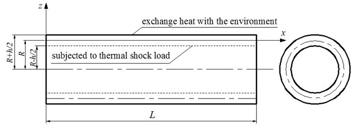
A homogeneous cylindrical shell with length , the radius of middle surface and thickness is shown in Fig. 1. Every point of the cylindrical shell with the simply supported edges has no initial displacement and initial velocity. An orthogonal curvilinear coordinates are referred, in which the -axis coincides with the generatrix of the middle surface of the shell before deforming, measured from the left end. is in the circumferential direction, and is in the transverse direction measured from the middle surface, positive outward. The dynamic response of the shell with inner surface subjected to thermal shock and outer surface exchanging heat with the environment is studied.
Fig. 1Sketch of the homogeneous thin cylindrical shell subjected to thermal shock
2.1. Linear geometrical equations
The corresponding displacements in the mid-surface of the cylindrical shell are designated and in directions of and respectively. Considering axisymmetric deformation, the displacement in the direction of is zero. Based on the classical shell theory, the displacements at an arbitrary point could be expressed as:
The normal strains at an arbitrary point can be expressed as:
in which the normal strains at an arbitrary point on the mid-surface of the deformed shell are given by , . The curvatures are ,
This set of strain-displacement relationships for a cylindrical shell can be obtained by specifying the orthogonal curvilinear coordinates and its Lame coefficients in the straindisplacement relations of a general shell theory.
2.2. Constitutive equations
Disregarding the stress components , and , the linear thermo-elastic constitutive equations are expressed as:
where and are the normal stresses in -and -directions, respectively. , and are Young’s modulus, thermal expansion coefficient and Poisson’s ratio of the material, respectively. is temperature rise.
Substituting Eq. (2) into Eqs. (3a) and (3b), the constitutive equations expressed by the displacements and are obtained as:
in which Integrating and along the thickness direction, the membrane forces and the bending moments per unit area are given by:
Substituting Eqs. (4) into Eq. (5) obtains the membrane forces and the bending moments per unit area expressed by displacements as:
where stiffness coefficients are , , , . In addition, the thermal membrane force and the thermal bending moment are defined as:
2.3. Motion equations and dynamic governing equations
Denote and as strain energy and kinetic energy, respectively. The principle [9] is adopted. i.e.:
where is the time. Expressed by normal strains and displacements, Eq. (7) becomes:
in which is the mass density of the material. Substituting Eq. (1), Eq. (2) and Eq. (5) into Eq. (8), with the application of the usual integration and variational procedures, ignoring the rotatory inertia item of the thin shell at the same time, the following equations of motion are established for cylindrical shell:
where is the mass per unit area.
Substituting Eqs. (6) into Eqs. (9) obtains the governing differential equations of the problem in terms of the mid-surface displacements as following:
here, the simply supported two edges are considered; boundary conditions are:
Considering that the cylindrical shell is static at the balance position at the beginning, the initial conditions are:
Introduce the following dimensionless quantities for easy solution:
where is the time interval of the solving process and usually takes very short because of the transient problem. The dimensionless governing equations and the dimensionless initial and boundary conditions are:
In the above equations, there are the thermal membrane forces and the thermal bending moments that depend on the temperature field. As a result, the solutions of the temperature field should be obtained before solving the governing equations.
3. The transient temperature field
The dynamic response of cylindrical shell which is under the initial steady-state heat balance environment and suddenly subjected to uniform thermal loads on its inner surface is investigated. The thermal shock load is exponential function type with being amplitude of thermal load and the parameter of the load change. Assume that the temperature of the environment is invariable and the side of the shell is adiabatic to the environment, so the problem is one-dimension heat conduction in the uniform media. The internal temperature field of the shell varies with time and the location of the thickness direction, and its outer surface exchanges heat with the external environment. Based on the uncoupled linear thermoelasticity theory, the change of temperature in the elastic body due to working of elastic deformations is neglected [19]. Thus the heat equation in the absence of internal heat sources reduces to:
The thermal initial conditions and the boundary conditions on the outer and the inner surfaces, are specified as
where , , , are the specific heat capacity, mass density, thermal conductivity, heat exchange coefficient between the outer surface of the shell and the environment, respectively. is the changes of absolute temperature relative to the amount of reference temperature.
Eqs. (14) and (15) constitute initial boundary value problems. Due to the partial differential operations in the equations, so it’s too difficult to solve them directly. Therefore, a temperature function that identically satisfies thermal boundary conditions at the edges and the Laplace transformation technique are employed to reduce equations governing the transient heat conduction to an ordinary differential equation (ODE) in the thickness coordinate, which is then solved by the power series method. Using the inverse Laplace transformation for that result, the temperature in the time field could be obtained. This process is as follows.
Take the Laplace transform and define [20]:
Considering the differential properties of the Laplace transformation, Eq. (14) and Eq. (15) are transformed into:
Eq. (17), Eq. (18) and Eq. (19) are the linear constant-coefficient differential equations and the boundary value conditions with respected to complex . The series solution of Eq. (17) is supposed by:
Substituting Eq. (20) into Eq. (17) and then expanding it according to because every coefficient of power of is zero, so an equation is obtained as:
where takes the integers, i.e. 0, 1, 2 3. Solving all equations together with the boundary conditions Eqs. (15), the series solution of with respect to could be obtained.
In order to obtain the temperature in the time field, use the inverse Laplace transformation for Eq. (20), that is:
Actually, we can only obtain the implicit solution of with infinite series, which is very complicated. In the practical calculation, we take some finite series about to get the approximate solution of .
4. DQM solutions to governing equations
The dynamic governing Eqs. (12a), (12b) are partial differential counterparts, which are difficult to solve via some analytical solutions. Herein, the method of differential quadrature (DQM) [21, 22] is used to seek a numerical solution of Eqs. (12a), (12b) together with initial and boundary conditions Eqs. (13a)-(13c). With the excellent convergence of DQM, satisfied results can be obtained using just a few grid points. Discretizing the derivatives in the governing equations, the initial and boundary conditions by using the DQM in the space domain and the time domain obtain algebraic equations in terms of the grid point displacements, which can be easily solved numerically. After spatial discretization, all grid point displacements in column vector form can be expressed as:
where the first and the second subscripts of the element indicate the grid point of the space domain and the time domain. and are the number of grid points of time domain and space domain, respectively.
After discretization using DQM, Eqs. (12a), (12b) are converted into a set of algebraic equations as follows:
where and are the DQ weight coefficient matrices of the th order derivative, respectively. With the Lagrange interpolating function used as the basis function, the weight coefficient matrices for the first order derivatives are determined as follows [22]:
The weight coefficient matrices for the second to fourth derivative are expressed as:
Similarly, after spatial discretization by DQM, the initial and boundary conditions Eqs. (13a), (13b), (13c) can be written as:
where and are the coordinates of the grid points are chosen as [22]:
In the solving process, more grid points in the time domain are taken to improve the precision of the results. But, less grid points in the space domain are taken to reduce the difficulty of the process. The numbers of grid points depend on the convergence and precision of the results. All grid point displacements can be obtained by solving algebraic Eqs. (23)-(26) numerically.
In order to obtain the transient thermal stresses, Eqs. (4a), (4b) are discretized by DQM as:
5. Numerical results and discussion
For all the following numerical computations, a cylindrical shell made of Cu is considered. The material properties are given in Table 1.
Table 1The material properties of Cu
Material | [W/(m·K)] | [J/(kg·K)] | (GPa ) | (1/K) | (kg/m3) | |
Cu | 387.6 | 381 | 125 | 17.1×10⁻⁶ | 8978 | 0.32 |
If no special specification, the geometries of the cylindrical shell are 4 m, 2 m and 0.04 m. The parameters of thermal shock loading are 200 K and 10. There is heat exchange between the outer surface of the shell and the environment, the heat exchange coefficient is 100.
5.1. Transient temperature field
Theoretically, the solution with infinite series of the one-dimensional heat conduction equation can be obtained. Actually, we can only take some finite series. The transient temperatures in the inner, middle and outer surfaces of the shell in case of 4, 9, 14 are shown in Fig. 2, where, we take , [–0.5, 0.5] to facilitate to distinguish the different surfaces. The figure indicates that the convergence of the results is very excellent. It is clear that the results of 9 and 14 are very close. When the number of is larger than 14, the results are independent of . This concludes that, 14 terms are sufficient to obtain satisfied numerical results. So the value 14 will be adopted in the following computations. In Fig. 3, the transient temperature fields at different position are shown. It can be observed that the temperature at the position that is closer to the inner surface rises faster. All the transient temperature at different position approaches steady state when the time goes on.
Fig. 2The transient temperature field in the inner, middle and outer surfaces of the shell

Fig. 3The transient temperature field at different position
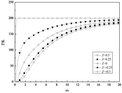
Fig. 4 and Fig. 5 show the variations of the thermal membrane force and the thermal bending moment with respect to time, respectively. Although the thermal membrane force tends to a stable value with increasing time, the thermal bending moment increases suddenly at first and then tends to zero.
In addition, the dynamic response of cylindrical shell subjected to sinusoidal thermal load is investigated by using the DQM. The parameters of the thermal loading are 200 K and 2. In Fig. 6, the transient temperature fields at different position are shown under the above load. It can be observed that the temperature at the position that is closer to the inner surface rises faster. All the transient temperatures at different positions are periodically varying. When the shell is given different thickness and subjected to sinusoidal thermal load, Fig. 7 and Fig. 8 show the variations of the thermal membrane force and the thermal bending moment with respect to time, respectively. It can be seen that the thermal membrane forces and the thermal bending moments vary sinusoidally. It’s due to the fact that the shell is subjected to the sinusoidal thermal loading.
Fig. 4Variation of the thermal membrane force with time
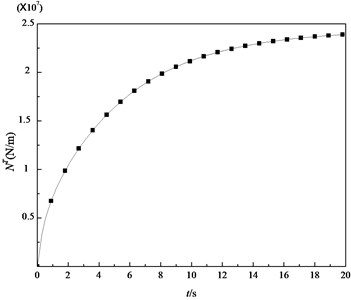
Fig. 5Variation of the transient thermal bending moment with time
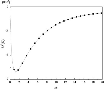
Fig. 6The transient temperature fields at different positions of the shell under sinusoidal thermal load
5.2. Transient displacements and stresses
After obtaining the transient temperature field, the thermal membrane and the thermal bending moment, the dynamic responses of the displacements and stresses of the shell could be analyzed by means of DQM. That is to say, displacements could be obtained by solving Eqs. (23a), (23b). Substituting the obtained displacements into Eqs. (28a), (28b), the dynamic stresses are got.
In order to guarantee the convergence of the numerical results, the numbers of grid points must meet conditions of 7, 20. Herein, we take the number of grid point ×15×53 so as to get more accurate numerical results.
Fig. 7Variations of the thermal membrane forces of the shell under sinusoidal thermal loading with time for some specified thickness

Fig. 8Variations of the thermal bending moments of the shell under sinusoidal thermal loading with time for some specified thickness
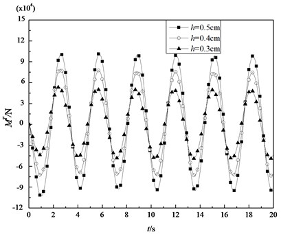
Fig. 9 shows the transient deflection at the midpoint in the middle surface of the shell with 4 m, 2 m and different thickness. It can be seen that the deformation of the shell increases with the decrease in the value of thickness. Fig. 10 depicts the transient deflection at the midpoint in the middle surface of the shells with 4 m, 0.04 m and different radius. It is indicated that the deflection of shell increases with the increasing radius. Fig. 11 describes the central deflection in the middle surface of the shells with 2 m, 0.04 m and different length. It is clear that different length has little influence on the transient deformation. From above three figures, it is concluded that the deflections increase with increase of time, which similar to variations of the thermal membrane force with time. It is due to the fact that there are the thermal bending moments in both the axial direction and the circumferential direction of the cylindrical shell under thermal shock that produces the opposite direction deflections at the midpoint in the middle surface. These deflections offset each other largely. Meanwhile, the thermal membrane force in the circumferential direction increases gradually and tends to a stable value with increasing time, which is dominant influence for the transient deflection.
Fig. 9The transient central deflection in the middle surface of the shell with different thinkness (L= 4 m, R= 2 m)
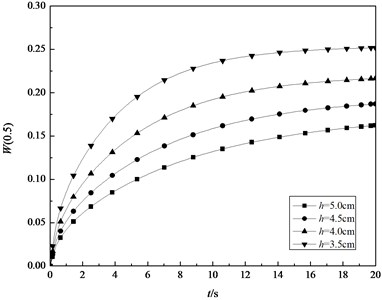
Fig. 10The transient central deflection in the middle surface of the shell with L= 4 m, h= 0.04 m and different radius
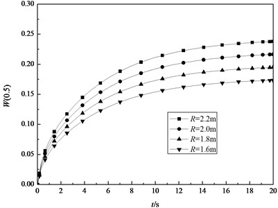
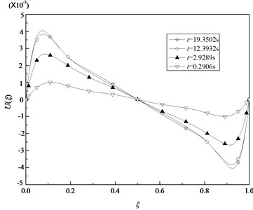
Fig. 12 and Fig. 13 show the axial displacement and the deflection in the middle surface along the length of the cylindrical shell for specified time, that is 0.2906 s, 2.9289 s, 12.3932 s and 19.3502 s. The geometric parameters of the shell are 4 m, 2 m and 0.04 m. The boundary conditions of both two edges are identical so that the curves of the axial displacement and the deflection in the middle surface along the length are all symmetrical related to the middle position. The axial displacement of the midpoint is close to zero.
Fig. 11The transient central deflection in the middle surface of the shell with R= 2 m, h= 0.04 m and different length
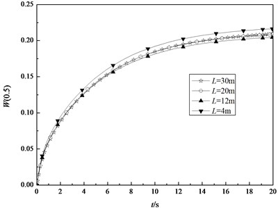
Fig. 12Variation of axial displacements U in the middle surface with ξ for some specified time
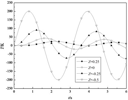
Through the above analysis, it is obvious that the axial displacement and the deflection change with the axial coordinate . So, on the basis of Eq. (28a), (28b), the normal stresses and are all the functions of and . In the analysis of the transient stresses, the case of fixed and different and the case of fixed and different , are respectively considered. Fig. 14 and Fig. 15 depict the variations of the normal stresses and in the different surfaces with time, given 0.1883, respectively. It is indicated that the stresses and from the inner surface to the outer surface increase gradually. The absolute values of the stresses in the inner surface are apparently higher than the ones in the outer surface. The stresses in the inner surface are tensile and the ones in the outer surface are compressive. There is a surface between the inner surface and the outer surface, the stresses of which are zero, but it is not geometric mid-surface. With the transient temperature of the shell tending to stability, the stresses in the different surfaces converge to a same fixed value.
Fig. 13Variation of deflection W in the middle surface with ξ for some specified time
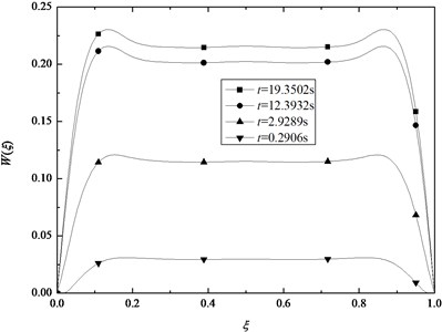
Fig. 14The transient normal stresses σxx(z) in the different surfaces (ξ= 0.1883)
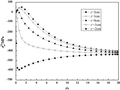
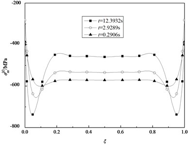
Fig. 16 and Fig. 17 show the variations of the normal stresses and in the inner surface along the length of the cylindrical shell for some specified time, respectively. It is clear that the curve of the stress in any instant of time is symmetrical related to the middle position. In the analysis of the dynamic responses of the stresses of fixed and different , we select several grid points from the edge to the middle position to study. Based on the forementioned analysis, it is obtained that the normal stresses in the inner surface are strongly affected by thermal shock loads.
Fig. 15The transient normal stresses σθθ(z) in the different surfaces (ξ= 0.1883)
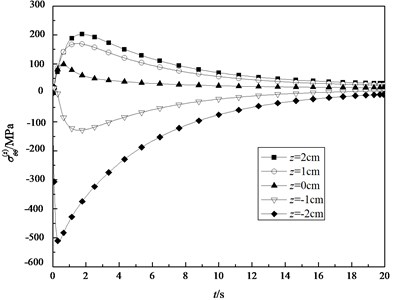
Fig. 16Variation of the normal stresses σxx(z) in the inner surface with ξ for some specified time
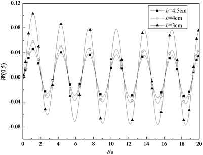
When the shell is subjected to sinusoidal thermal loading and given different thickness, the variations of the transient central deflection in the middle surface of the shell with time are shown by the Fig. 18. It can be seen that all the transient temperatures at different position are periodic variations. And the deformation of the shell increases with the decrease in the value of thickness.
Fig. 17Variation of the normal stresses σθθ(z) in the inner surface with ξ for some specified time
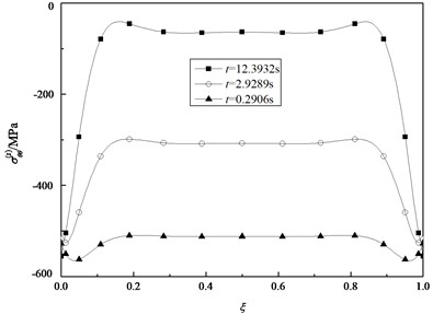
Fig. 18Variations of the transient central deflection in the middle surface of the shell under sinusoidal thermal loading with time for some specified thickness
6. Conclusions
In present work, based on the classical shell theory, the dynamic responses of a homogeneous axisymmetric thin cylindrical shell subjected to uniform thermal shock load on the inner surface are analyzed. The boundary conditions are both edges simply supported. Firstly, the transient temperature is obtained by using the combination of Laplace transform and series expansion. Then, differential quadrature method is introduced to obtain the numerical solutions of the dynamic responses of the displacements and stresses of the shell. Through analyzing, the following conclusions can be obtained:
1. In the process of thermal shock, the transient temperature of the shell causes the thermal membrane force and the thermal bending moment. With the time increasing, the temperature field tends to stability. The thermal membrane force increases from zero and tends to a stable value with time increasing. The thermal bending moment reaches a peak at first from zero and then tends to zero with time goes on.
2. The thickness, radius and length impact on the transient deflection of the shell. The deflection of more thick shell responds slower and tends to a smaller stable value, and the ones of bigger radius responds faster and tends to a bigger stable value. But taking the bigger length, the effects on the transient deflection is little. The thermal membrane force in the circumferential direction increases gradually and tends to a stable value with increasing time, which is dominant influence for the transient deflection.
3. The boundary conditions of both two edges are identical so that the transient axial displacements, deflections and normal stresses along the length are all symmetrical related to the middle position.
4. The normal stresses caused by thermal shock are the functions of axial coordinate, radial coordinate and time variable. The stresses in the inner surface are apparently higher than the ones in the outer surface with the same axial coordinate. With the temperature of the shell tending to stability, the stresses in the different surfaces converge to a same fixed value. All the transient stresses reach a peak at first and then converge to a different fixed value.
5. When the shell is subjected to sinusoidal thermal loading, the variations of the temperature fields, the thermal membrane force, the thermal bending moment and the deflections of the shell are all periodic functions with respect to time.
References
-
Yan Z. D., Wang H. L. Thermal Stress. Higher Education Press, Beijing, 1993, (in Chinese).
-
Tauchert T. R. Thermal shock of orthotropic rectangular plates. Journal of Thermal Stresses, Vol. 12, Issue 2, 1989, p. 241-258.
-
Tanigawa Y., Akai T., Kawamura R., Oka N. Transient heat conduction and thermal stress problems of a nonhomogeneous plate with temperature-dependent material properties. Journal of Thermal Stresses, Vol. 19, Issue 1, 1996, p. 77-102.
-
Wang B. L., Mai Y. W., Zhang X. H. Thermal shock resistance of functionally graded materials. Acta Materialia, Vol. 52, Issue 17, 2004, p. 4961-4972.
-
Zhao J., Ai X., Huang Ch. Z., et al. An analysis of unsteady thermal stresses in a functionally gradient ceramic plate with symmetrical structure. Ceramics International, Vol. 29, Issue 3, 2003, p. 279-285.
-
Xu Y. J., Tu D. H., Ma S. H. J. The transient thermal stresses of a functionally gradient materials plate under warming and cooling with the physical parameters changing with temperature. Mechanical Strength, Vol. 27, 2005, p. 510-517.
-
Han J. C., Wang B. L. Thermal shock resistance enhancement of functionally graded materials by multiple cracking. Acta Materialia, Vol. 54, Issue 4, 2006, p. 963-973.
-
Cho H., Kardomateas G. A., Valle C. S. Elastic dynamic solution for the thermal shock stresses in an orthotropic thick cylindrical shell. Journal of Applied Mechanics, Vol. 65, 1998, p. 184-193.
-
Mirzavand B., Eslami M. R., Shakeri M. Dynamic thermal post-buckling analysis of piezoelectric functionally graded cylindrical shells. Journal of Thermal Stresses, Vol. 33, Issue 7, 2010, p. 646-660.
-
Safari A., Tahani M., Hosseini S. M. Two-dimensional dynamic analysis of thermal stresses in a finite-length FG thick hollow cylinder subjected to thermal shock loading using an analytical method. Acta Mechanica, Vol. 220, Issue 1-4, 2011, p. 299-314.
-
Guo L. C., Noda N. An analytical method for thermal stresses of a functionally graded material cylindrical shell under a thermal shock. Acta Mechanica, Vol. 214, Issue 1-2, 2010, p. 71-78.
-
Cavalcante M., Marques S., Pindera M. J. Transient finite-volume analysis of a graded cylindrical shell under thermal shock loading. Mechanics of Advanced Materials and Structures, Vol. 18, Issue 1, 2011, p. 53-67.
-
Santos H., Soares C. M. M., Soares C. A. M., Reddy J. N. A semi-analytical finite element model for the analysis of cylindrical shells made of functionally graded materials under thermal shock. Composite Structures, Vol. 86, Issue 1-3, 2008, p. 10-21.
-
Dai H. L., Rao Y. N. Nonlinear dynamic behavior of a long temperature-dependent FGM hollow cylinder subjected to thermal shocking. Science and Engineering of Composite Materials, Vol. 21, Issue 2, 2014, p. 267-280.
-
Safari-Kahnaki A., Hosseini S. M., Tahani M. Thermal shock analysis and thermo-elastic stress waves in functionally graded thick hollow cylinders using analytical method. International Journal of Mechanics and Materials in Design, Vol. 7, Issue 3, 2011, p. 167-184.
-
Yun Y. W. Thermal stress distribution in thick wall cylinder under thermal shock. Journal of Pressure Vessel Technology, Vol. 131, Issue 2, 2009, p. 021212-021217.
-
Fillery B. P., Hu X. Z. Compliance based assessment of stress intensity factor in cracked hollow cylinders with finite boundary restraint: Application to thermal shock part II. Engineering Fracture Mechanics, Vol. 79, 2012, p. 18-35.
-
Ying J., Wang H. M. Axisymmetric thermoelastic analysis in a finite hollow cylinder due to nonuniform thermal shock. International Journal of Pressure Vessels and Piping, Vol. 87, Issue 12, 2010, p. 14-720.
-
Fung Y. C., Tong P. Classical and Computational Solid Mechanics. World Scientific Publishing Co., Singapore, 2001.
-
Hu X. H. The Practical Handbook of Laplace Transform and Z-transform. Electronic Industry Press, Beijing, 1988, (in Chinese).
-
Shu C., Yao Q., Yeo K. S. Block-marching in time with DQ discretization: an efficient method for time-dependent problems. Computer Methods Applied Mechanics and Engineering, Vol. 191, Issue 41-42, 2002, p. 4587-4597.
-
Zhang J. H., Li S. R. Free vibration of functionally graded truncated conical shells using the GDQ method. Mechanics of Advanced Materials and Structures, Vol. 20, Issue 1, 2013, p. 61-73.
About this article

This work was financially supported by the National Natural Science Foundation of China (Nos. 11262010, 11272278), the Fundamental Research Funds for the Universities of Gansu and the Postdoctoral Science Foundation of China (No. 20110491664). The authors gratefully acknowledge all of the support.
