Abstract
Prevention of damage to an elastic structure, such as the vibration of floodgate, requires serious consideration in the design. Hydrodynamic load characteristics and structural response under flow-induced vibration are mainly influenced by inertia, damping and elastic, geometric characteristics and hydraulic parameters. The purpose of this study is to investigate the dynamic behavior of sliding dam gates in the response to stimulation caused by fluid flow. The main drawback of the analytical models presented in the vibration dam gates is that, they supposed it as a linear system and non-linear behavior of the gates feedback are not considered in the in force calculations. Physical model of the gate in reality, is a self-excited model. So, expression of the force applied to the fluid by adding a harmonic excitation system is incompatible with the physical reality. If the non-linear behavior of the fluid pressure variation considered, vibration dam gate analytical models should be considered as a periodic models to analysis of the vibrational behavior. The qualitative analysis of the problem can be well approximated by the force, which should be able to establish the gate oscillatory behavior. In this paper, at first a nonlinear self-excited mathematical model for the fluid flow induced vibration, in sliding gate dam is presented. This model is based on assumptions that obtained by qualitative analysis of vibration dam gates experimental results. Results show that proposed model can produce permanent and self-stimulated vibration behavior. Then in the next stage the dynamic behavior of sliding dam valves, in response to flow excitation studies in ANSYS. Finally, to achieve the optimal valve geometry, numerical results for various shapes of valves are compared with experimental data.
1. Introduction
Vibrations induced by the fluid on the gate sliding dams are one of the main sources of wear and failure in this type gates. From around 90 s, many studies have been done in this regard. These researches can be classified into theoretical and experimental works [1-4]. Existing analytical models for the vibrations of the sliding gates has been studied by many researchers. For example Nadashr [5], Kulkmn [6] and Anamii [7], have done a lot of analytical work in this area. However, still many aspects of the vibration behavior of the sliding gate analysis are not investigated properly. Such weaknesses of these analytical model includes self-excited vibration, existence of wide spectrum of frequencies and multi-harmonic behaviors, which cannot be explain by these models. In the previous studies, which have been conducted, the effects of important parameters such as Reduced Velocity and the mass damping coefficient (Scruton number) are not considered [8-10].
Tang and Nadashr [8] using experimental model, studied the vibration induced qualitative behaviors of the gate. Spectral analysis of the excitation-force and gate-response signals permitted identification of the main characteristics of the interaction process. The main similitude parameters governing this hydro-elastic phenomenon are shown to be the reduced velocity and the mass-damping coefficient. In [10] an alternative dimensionless damping parameter, , was defined for cylinders experiencing flow-induced vibration. It overcome the limitations of “mass-damping” parameters, which first came into use in 1955. It was shown that the method of modal analysis may be used to generalize the application of to flexible risers.
When the stream flowing under the gate is unstable, the resulting pressure fluctuations cause the hydrodynamic force to fluctuate too. The latter’s downpull component has been the subject of numerous researches and experiments by among others: Simmons [11] who conducted tests (based on the air model) on the flow around the gate, Colgate [12] carried out downpull pattern tests and natural measurements, and also Sagar [13] suggested various lift gate designs. The fluctuations in the hydrodynamic force are the cause of flow-induced vibrations. Many studies have been undertaken to determine this mechanism and the optimum lower edge shape minimizing flow-induced vibrations [5, 6, 8]. In the case of gate underflow, the most common cause of vibration is the instability of the single layer separating from the gate lip (the instability induced excitation mechanism) [14, 15]. Experimental research into this mechanism for a rectangular plate with two degrees of freedom was done by Billeter [16, 17] who found that the vibrations were caused by two phenomena: the streamline impinging-leading-edge-vortex (SILEV) mechanism and the instability of the shear layer (ISL) in the tail water.
In [18] the onset of fluid-elastic instability is analyzed for different structural parameters, Scruton number and reduced velocity. The simulations have been carried out with the code NSMB (Navier-Stokes Multi Block) by using turbulence modelling methods URANS and DDES (Delayed Detached Eddy Simulation).
In this paper based on the experimental results of gates vibration and its relation to dimensionless parameters (reduced velocity and the mass-damping coefficient), a mathematical self-excited vibration model develops for dams gate. First, an approximate model is based on a degree of freedom of gate dynamics is considered. Then, properties of flow-induced force, according non-dimension parameters, experimental results and qualitative vibrational behavior of gate for various shapes including flat, Chamfer and rounded, are considered. By using the some properties of the proposed mathematical functions that are applicable to the induced force, the dynamic behavior of the resulting model is investigated numerically. Proposed method for studying and modeling of induced-vibration of dam gates is a mathematical self-excited one, which is compatible with experimental works. However proposed model is not a unit mathematical model to define a dynamics of problem, but it is an analytical method with more precious than linear models, which it can predict nonlinear behaviors such as non-harmonic conditions and use as more precious one.
2. Modelling gates of self-excited vibration
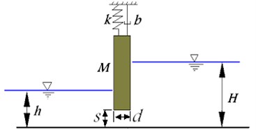
The behavior of a sliding gate is represented by a cantilever system with the fixed end at the sea bed. As shown in Fig. 1, such a single-degree-of-freedom system under the action of the exciting force and linear damping is represented by the differential Eq. (1):
where, is a nonlinear force acts on gate which is a function of velocity and opening ration of gates.
Fig. 1Vibrational model of gate
By making the variables as the dimensionless ones used, the following equation is obtained:
In Eq. (2) is a nonlinear, so it is necessary to consider the effects of its weight. Furthermore, the physical systems such as dam gates has a self-exciting behavior inherently. Therefore, time cannot be considered as the force parameters which it is incompatible with problem. is specified according a qualitative vibrational behavior in [8, 18]. So, force function is calculated by experimental results and tests.
Based on experimental results presented in [8, 19] the force function considered as:
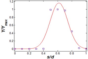
a) There is a specified geometry coefficient value, which the force reaches its maximum. Away from this value (increasing or decreasing), the force approaches zero. Force function in relative to geometry coefficient shifted from zero to maximum value in about 0.4-0.5, and then it reduces till reaches zero. Also, for very large values (greater than 1) becomes negative and resorting.
b) Force function is a maximum at a certain value of dimensionless velocity (), which depends on gate geometry. Also, by increasing and reducing the , the force decreases.
c) According to geometry, changes resulting in increasing resorting hydrodynamic force in normal direction of the gate. However, due to gate weight, hydrodynamic force increasing is limited. Hydrodynamic force equation can be found as:
where, and are reprsentive of the reduced velocity and opening ratio effects respectively, which obtained as:
In Eq. (6) is a positive parameter which can be calculated as:
expresses the intensity or the magnitude of the force related to coefficient. In fact, it depends on fluid properties.
3. Numerical simulation of flow under lift gate
Dynamic equations and force specifications can be divided into three category. Numerical results for these three conditions in Eq. (4)-(6) are obtained.
In the first condition, steady behaviors without vibration, which accurse for the values away from the or . These kind of specification are illustrated in Figs. 2 and 3.
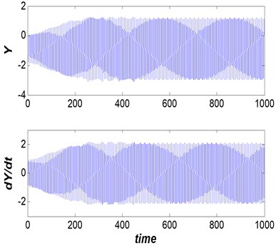
Steady vibration behaviors (partially periodic orbits) with the specified periods for values close to and . The performance of this condition is depicted in Figs. 4 and 5.
Fig. 2Dam gate behavior (Vr= 5, s/d= 0.5 and η= 25), steady non-oscillation behavior
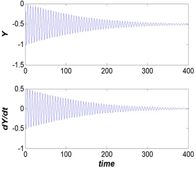
Fig. 3Dam gate behavior (Vr= 2.5, s/d= 0.1 and η= 25), steady non-oscillation behavior
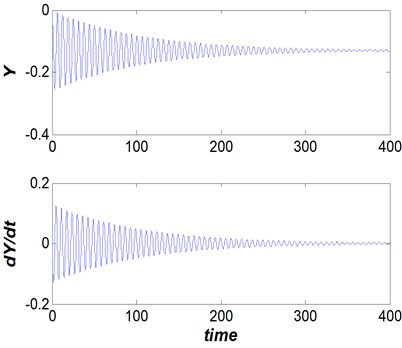
Fig. 4Dam gate behavior (Vr= 2.5, s/d= 0.5 and η= 30), steady vibrational (periodic) behavior
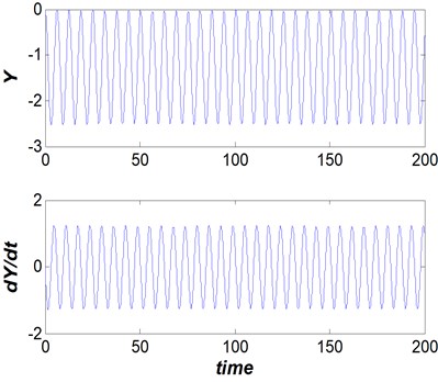
Fig. 5Dam gate behavior (Vr= 2.5, s/d= 0.5 and η= 25), steady vibrational (periodic) behavior
In the third group, existence of non-harmonic and non-regular behavior for values close to and are illustrated in Figs. 6 and 7.
Due to nonlinearity of proposed model in this paper, non-periodic behavior does not mean chaos of system, and they are as semi-periodic behaviors.
In order to validate the proposed model, quality adaption of model with experimental results and the laboratory test is done for relative dimensionless displacement versus decreased velocity and geometry coefficient in Figs. 8 and 9.
As Shown in Figs. 8 and 9, proposed mathematical model for various dimensionless parameters is well suited with experimental results which presented in [8, 18].
4. Valve shapes effects on hydrodynamic force
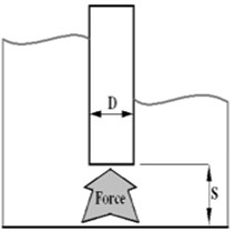
In order to analyze the hydrodynamic forces in gates, in this paper the general behavior of the three valves that are standard in the construction of valves are considered (Fig. 11); valve with flat edges (flat), the bottom edge of the triangle (Chamfer) and valve with rounded edges (quarter circle).
Fig. 6Dam gate behavior (Vr= 2.5, s/d=0.5 and η= 20), steady non-periodic behavior
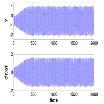
Fig. 7Dam gate behavior (Vr= 2.5, s/d= 0.5 and η= 19.5), steady non-periodic behavior
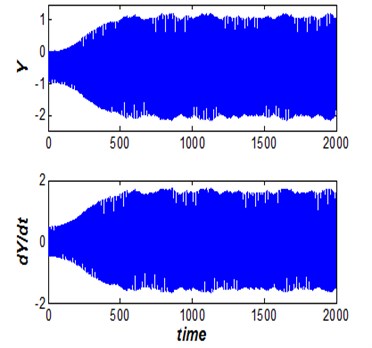
Fig. 8Vibrational amplitude versus reduced velocity (s/d= 0.5 and η= 25)
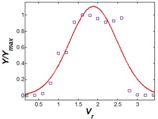
Fig. 9Vibrational amplitude versus geometry coefficient (Vr= 2.5 and η= 25)
The fluid is considered as water properties and Boundary condition for force analysis are: the flow entrance, the free surface of the fluid, walls and symmetry. In the previous works [18-21] reduced velocity in the beneath of valve is considered as a variable, in this paper corresponding pressure which is related to reduced velocity and its measurement is easier is used as a variable. Corresponding pressure is vary in the range 125-700 Pa according reduced velocities in [22].
Fig. 11Valves geometry models
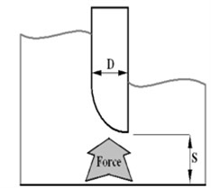
a) Flat
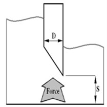
b) Chamfer
c) Rounded
5. Results
In this section, simulation is performed for the various forms of valves and results are discussed. Three valves including flat, chamfer and quarter circle are modeled and analyzed. Then results compares with experimental results available in the reference [22]. Finally, in order to investigate the effects of geometry parameter on hydrodynamic force, various valves shape effects comparison is done.
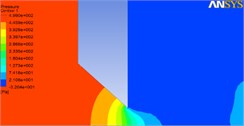
Each of the valve models modeled in Ansys software, then the triangle meshing for classification of space elements are used. Pressure counters for different valve geometries flat, chamfer and rounded ones are shown in Figs. 12-14 respectively.
Fig. 12Pressure counter for different opening ratios in flat valves
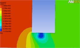
a) 0.7
b) 0.5
c) 0.1
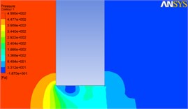
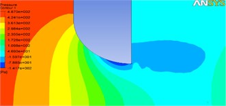
Fig. 13Pressure counter for different opening ratios in chamfer valves
a) 0.8
b) 0.4

c) 0.1
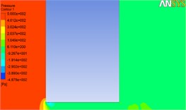
Fig. 14Pressure counter for different opening ratios in rounded valves
a) 0.1
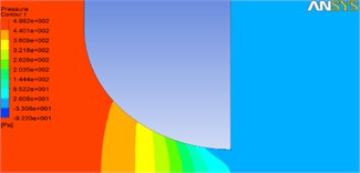
b) 0.2
As shown in Fig. 12, the pressure drop occurs beneath the valve in larger opening ratios, which leads to the turbulence of the flow. Results demonstrate that 0.7, 0.8 and 1 are critical opening ratios amounts for flat, chamfer and round valves respectively. So, round valve shows best performance which flow separation and vibration occurs less for this case.
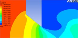
In order to investigate the flow condition in more detail, the flow velocities for round valve with different opening ratios are illustrated in Fig. 15.
Fig. 15Flow velocity for different opening ratios in rounded valves
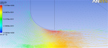
a) 1
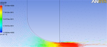
b) 0.2
Fig. 16 demonstrate the validation of the developed model with experimental results in [4]. Then to evaluate the effects of dimensionless parameters effect on flow, simulation results of flat valve for various geometry coefficient and reduced velocities are illustrated in Fig. 17.
As shown in Fig. 16, the simulation results are fitted to experimental results properly in the range of 0-0.5 and 1-1.5 of . Also, existence of the difference between proposed model and experimental one is because of some nonlinear and turbulence phenomenon in critical amount of .
Fig. 17 demonstrate the effects of various opening ratios. It is obvious that critical opening ratio occurs in 0.7, which has the maximum amplitude.
In Figs. 18 and 19 the simulation results for various opening ratio are compared with experimental results in [22]. It shows that proposed model in this paper can be properly track the experimental results for various opening ratios.
Fig. 16Effects of opening ratio on vibrational amplitude in Vr= 4 for flat valve
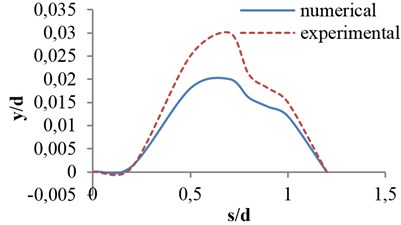
Fig. 17Effects of dimensionless parameters on vibrational amplitude for flat valve
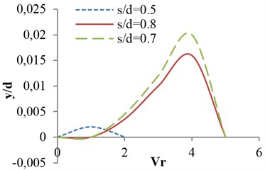
Fig. 18Effects of reduced velocity on vibrational amplitude in critical opening ratio s/d= 0.7, for flat valve
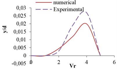
Fig. 19Effects of reduced velocity on vibrational amplitude in opening ratio s/d= 0.5, for flat valve
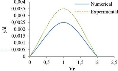
Fig. 20Effects of valve shape on vibrational amplitude in opening ratio s/d= 0.8
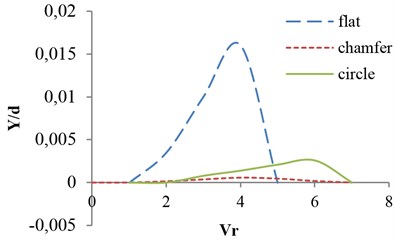
Fig. 21Effects of valve shape on vibrational amplitude in opening ratio Vr= 4
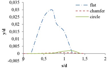
Finally, simulation results are performed for various valve shapes. Variation of amplitude against two main dimensionless parameters, reduced velocity and geometry coefficient, for three shapes are shown in Figs. 20 and 21 respectively.
As can be observed in Fig. 20, for the same opening ratios, the amplitude of vibrations to the valve with the flat edge is so much more than the other two modes. Moreover, the valve with the bottom edge of the triangle (Chamfer) has the lowest amplitude. Valves with quarter-circle and steep edges, in the opening ratios smaller than 0.7, do not vibrate and their vibration amplitude shifted to greater opening ratios.
6. Conclusions
In this paper nonlinear and self-excited analytical model developed for studying vibrational behavior of the dam sliding gates based on experimental results. Simulation results shows that proposed mathematical model enables to predict steady treatment without vibration, induced vibration and non-periodic behavior of the gate, properly. The main advantage of this method is to create an analytical model for the vibrations of the gate. With this model assistance it is possible to predict the vibrational behavior of the gate without the need for an experimental model. Also, investigation of dynamic and geometric parameters effects can be performed with the application of this analytical model. Certain types of valves were determined at different operating conditions. Their objective is to determine and evaluate critical operating conditions and optimal control of a valve. In other words, to reduce vibrational force and amplitude in the bottom of valve, an optimal geometry for various performance conditions are proposed. Numerical results for different valve shape demonstrate that valves with rounded edges and a sloping bottom has lower amplitude than the valves are flat. So, they have less possibility of damage to the dam wall, which can be useful in dam’s design.
References
-
Anami K., Ishii Noriaki, Knisely C. W., Oku T., Tsuji T. Dynamic stabilization of folsom dam tainter-gates by replacing hoist chains with cables. 11th International Conference on Vibration Problems, Lisbon, Portugal, 2013.
-
Bishop R. E. D., Hassan A. Y. The lift and drag forces on a circular cylinder oscillating in flowing fluid. Proceedings on Royal Society, Series A277 (1368), London, 1968.
-
Kostecki S. W. Numerical analysis of hydrodynamic forces due to flow instability at lift gate. Archives of Civil and Mechanical Engineering, Vol. 11, Issue 4, 2011, p. 943-960.
-
Billeter P., Staubli T. Flow-induced multiple-mode vibrations of gates with submerged discharge. Journal of Fluids and Structures, Vol. 14, Issue 3, 2000, p. 323-338.
-
Naudascher E. Flow-induced streamwise vibrations of structures. Journal of Fluids and Structures, Vol. 1, Issue 3, 1987, p. 265-298.
-
Kolkman P. A. Flow Induced Gate Vibration. Ph.D. Thesis, Delft Hydraulics Laboratory, Publication No. 164, 1976.
-
Anami K., Tsuji T., Ishii N., Oku T., Knisely C. W. The steel-rod breaking excitation method for analysis of dynamic stability of tainter gate. Journal of Structural Engineering, Vol. 58A, 2012, p. 552-558.
-
Thang N. D., Naudascher E. Vortex vibration of underflow gates. Journal of Hydraulic Research, Vol. 24, Issue 2, 1986, p. 133-151.
-
Anami K., Ishii N., Knisely C. W. Added mass and wave radiation damping for flow-induced rotational vibrations of skin plates of hydraulic gates. Journal of Fluids and Structures, Vol. 35, 2012, p. 213-228.
-
Vandiver J. K. Damping parameters for flow-induced vibration. Journal of Fluids and Structures, Vol. 35, 2012, p. 105-119.
-
Simmons W. P. Air model studies of hydraulic downpull on large gates. Journal of the Hydraulics Division, Vol. 1, 1959, p. 41-59.
-
Colgate D. Hydraulic downpull forces on high head gates. Journal of the Hydraulics Division, Vol. 11, 1995, p. 39-52.
-
Sagar B. T. A. ASCE hydrogates task committee design guidelines for high-head gates. Journal of Hydraulic Engineering, Vol. 121, Issue 12, 1995, p. 845-852.
-
Naudascher E. Hydrodynamic Forces. Brookfield, 1991.
-
Naudascher E., Rockwell D. Flow-induced vibrations: an engineering guide. A. A. Balkema, 1994.
-
Billeter P. Flow-inducted multiple-mode vibrations of gates with submerged discharge. Journal of Fluids and Structures, Vol. 14, 2000, p. 323-338.
-
Billeter P. Properties of single shear layer instabilities and vortex-inducted excitation mechanisms of thick plates. Journal of Fluids and Structures, Vol. 19, 2004, p. 335-348.
-
Shinde V., Marcel T., Hoarau Y., Deloze T., Harran G., Baj F., Cardolaccia J., Magnaud J. P., Longatte E., Braza M. Numerical simulation of the fluid–structure interaction in a tube array under cross flow at moderate and high Reynolds number. Journal of Fluids and Structures, Vol. 47, 2014, p. 99-113.
-
Mannini C., Marra A. M., Bartoli G. VIV–galloping instability of rectangular cylinders: Review and new experiments. Journal of Wind Engineering and Industrial Aerodynamics, 2014, Vol. 132, p. 109-124.
-
Kopp G. A., Kamprath M., Fathi S., Havel B., Martinuzzi R. J., Galsworthy J. Velocity measurements in the near wake of a freely-oscillating circular cylinder at lock-in. Proceedings of the 5th International Symposium on Engineering Turbulence Modelling and Measurements, Mallorca, Spain, 2002 p. 475-484.
-
Zhoua T., Razalib S. F., Haoc Z., Cheng L. On the study of vortex-induced vibration of a cylinder with helical strakes. Journal of Fluids and Structures, Vol. 27, Issue 7, 2011, p. 903-917.
-
Thang N. D. Gate vibration due to unstable flow separation. Journal of Hydraulic Engineering, Vol. 116, Issue 3, 1990, p. 342-361.
About this article

