Abstract
Active suspension is an effective approach to improve vehicle performance, and it is of great importance to attenuate the vibration of the rear part of heavy vehicles with freight. This paper proposes a new hybrid fuzzy proportional-integral-derivative (PID) controller with model adaptive wheelbase preview and wavelet denoising filter in an active suspension system for heavy vehicles with freight. A half vehicle model is first built, followed with the construction of the road excitation profiles of the shock and vibration pavement. After the design and implementation of the control method, four performance indices of the vehicle are evaluated. To verify the effectiveness of the proposed method, the control performance of the integrated controller and the separate function of every single controller are evaluated respectively. Numerical results show that the integrated control algorithm is superior to the single controllers and is effective in improving the vehicle performance as compared with other methods. Moreover, the wavelet denoising filter is shown to be an effective way to improve the vehicle performance and enable the stability of the system against noise.
1. Introduction
Suspension system is a crucial part of vehicles, and its main purposes are (1) to isolate the road disturbances from vehicle body so that the ride comfort can be ensured; (2) to keep good road holding capacity; (3) to offer good handling capacity; (4) to support the vehicle static weight [1]. In the open literature, investigations about the suspension systems of heavy vehicles become an emerging research interest with the prevalent use of commercial vehicles. Currently, there already exist some studies on heavy vehicles, such as the researches on pitch dynamics and suspension tuning of a two-axle heavy vehicle with unconnected suspension [2], kinematic and dynamic analysis of a heavy truck with individual front suspension [3], steering control for rollover avoidance of heavy vehicles [4]. Nevertheless, it is still insufficient in the field of suspension dynamics of heavy vehicles. So, the suspension system of heavy vehicles is set as the target of this work.
The type of suspension system is a crucial issue that mainly affects the performance of the vehicle. Regarding the suspension types, traditional passive suspension has a simple structure with conventional springs and linear viscous dampers, but it cannot meet the rapid development of the vehicle industry, as well as the high-level requirement of vehicle performance. In recent years, investigations on improving suspension performance have obtained tremendous attention. To improve the vehicle performance, the controllable suspension systems (semi-active and active suspension systems) have been introduced due to their flexibility in improving the vehicle performance [5].
In the semi-active suspension system, a damper with adjustable damping force, such as electrohydraulic variable damper or magneto-rheological damper, is often considered as the control objective of the research [6, 7]. In addition, an actuator, such as a hydraulic, pneumatic or electromagnetic actuator, which creates a desired force, is frequently applied to the active suspension system with a parallel configuration to the regular spring and linear viscous dampers [8]. Compared with the semi-active type, the active suspension system leads to a better performance with more power consumption and mass parameter consideration. In view of the superior performance of the active suspension system, this work applies the active suspension system to the heavy vehicle.
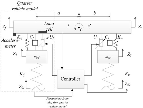
In order to control the suspension system, the vehicle dynamic model must be established first. At present, the most frequently used model is the quarter vehicle model, because it is a simple design for an independent suspension system and the control methods can be easily tested in this type of model. Moreover, researchers have also investigated half vehicle model, as shown in Fig. 1. The half vehicle model is represented as a four degree-of-freedom (DOF) system, which consists of a single sprung mass, two un-sprung masses (front and rear) and some advanced dissipations. The half vehicle model is capable of emulating and verifying the main performance of different control methods. As a result, to simplify the numerical simulation, the half vehicle model is employed in this paper.
Recently, the preview control has attracted much attention because of its effectiveness. The preview strategy was firstly used by Bender in an active suspension [9]. Then, the preview control was applied to a quarter vehicle model [10] and a half vehicle model [11], respectively. As far as the preview control method is concerned, one is called front preview and the other is wheelbase preview. For the front preview, a road sensor is put on the front axle to get the road information a few meters ahead of the two front wheels [12, 13].
Fig. 1Structure of a half vehicle model with proposed controller
However, there are some limitations for the front preview in some cases. For example, if there is a pothole with water on the road ahead of the vehicle, no matter an ultrasonic or a laser sensor is used, there could be certain measurement errors. In order to avoid uncertain errors that may come up in the real practice, the other preview method, wheelbase preview, is frequently considered in most cases. The basic idea of wheelbase preview is: when a vehicle is running on the road, the road input on the rear wheel is almost the same as that on the front wheel, but with a certain time delay. Thus, the road input of the front wheel can be used as preview information of the rear wheel, then an active force can be generated to isolate the upcoming road disturbance in advance [14, 15]. Therefore, the vehicle performance can be improved.
In the active suspension system, the wheelbase preview strategy is viewed as a low-cost solution, because it only controls the rear suspension so as to save the number of hydraulic actuators, sensors and control hardware for the front suspension. The wheelbase preview method is investigated in this work because of its simplicity and economy. By applying the preview control algorithm to the heavy vehicles, the sprung mass acceleration of the rear part of the vehicle can be reduced. The reduction of the rear sprung mass acceleration can effectively decrease the possibility of damage to the goods, and it has a significant meaning to the integrity of the goods, particularly for some vehicles carrying with fragile or expensive goods, such as glasses, electronic components and so on.
The latest research on wheelbase preview can be found from [15], in which a wheelbase preview control is applied to a full-tracked vehicle model. However, the loading, application, vehicle configuration, vehicle motion and vehicle speed between the heavy vehicle and the tracked vehicle are completely different, so the work in [15] cannot directly be applied to the heavy vehicle. Besides, the drawback of the existing wheelbase preview control is that the preview model is usually fixed. As many heavy vehicles are designed for load transportation, the loading usually varies a lot, and it affects the accuracy of the preview model. In view of the above concerns and limitation, an intelligent wheelbase preview control algorithm for heavy vehicle is studied.
In the proposed algorithm, a model adaptive wheelbase preview method is designed by placing a load cell in the front suspension system. Hence, the transient variation of the front loading in the preview model can be measured and updated timely. Even though the wheelbase preview control may not be better than the front preview, the wheelbase preview control can at least provide an alternative and low-cost solution to the chassis engineer to choose.
As far as control algorithms are concerned, there are many control algorithms for active suspension systems. Some researchers studied skyhook control [16, 17], H-infinity control [18], sliding mode control [19] and model predictive control methods [20]. Furthermore, some artificial intelligence algorithms are also applied to the active suspension systems, such as the adaptive neural network control [21] and fuzzy logic control [22]. Although there are many advanced control schemes, fuzzy control method is the most popular approach for active suspension systems because it is known as a soft and robust method [14]. Besides, the fast response and sensitiveness of the fuzzy controller determines that it is appropriate for the control of the suspension system [23]. Hence, fuzzy control method is adopted as the main control algorithm in this work.
Furthermore, numerous recent studies have proved the effectiveness of the integration of two individual controllers, such as the combination of the fuzzy control and sliding mode control [24], and the hybrid PID-sliding mode control [25]. Motivated by the above integrated control methods, this study proposes a simple but effective controller by combining some control methods together. Since the objective of wheelbase preview strategy is to offer a low-cost solution, the PID control algorithm, which is known as the most frequently used method in both academic and industrial areas, is considered as the second method of the integrated control.
Then, a hybrid fuzzy-PID method, which was proved to be effective in the suspension control of a half vehicle model [26], is employed in the proposed active suspension for the heavy vehicle. Nevertheless, the existing hybrid fuzzy-PID controller for active suspension systems is only designed for improving the ride comfort, but practically, a good active suspension should not only consider ride comfort, but also the road holding and handling capacity, etc. Therefore, the tuning and compromise of multiple objectives should be considered in the design of the hybrid fuzzy-PID controller, which is also one of the originalities of this work.
No matter how advanced the control algorithms are, sensors always introduce noise into the system during the measurement process. In most previous studies regarding active suspension control, it was assumed that all the state variables were measured without noise. However, the observed signal is a non-stationary signal, which is often influenced by the road disturbance and accompanied with noise. Therefore, in order to enhance the efficiency of the hybrid fuzzy-PID controller and to improve the system robustness against noise, a denoising filter is proposed in the active suspension system.
Wavelet transform, which is first introduced by Grossman and Morlet in 1984 [27], is verified as an effective method to filter noise. Chen and Li applied wavelet transform to eliminate noise for ultrasonic lamb wave signals [28]. Vong et al. also successfully applied wavelet to isolate ignition signal noise for automotive engine diagnosis [29]. As a result, a wavelet denoising filter is introduced in the design of the proposed controller to filter out the useless noise and hence to increase the system robustness.
In accordance to the presented review, a work which applies hybrid fuzzy-PID controller with model adaptive wheelbase preview and wavelet denoising filter to the heavy-vehicle active suspension together does not yet exist. Therefore, this project is the first attempt at the above considerations. Furthermore, unlike previous existing researches, the wheelbase preview method of this work innovatively considers the change of the vehicle body mass, which matches the loading nature of heavy vehicles.
To further prove the superiority of the proposed method, a comparison between the proposed active suspension system and other active suspension systems is also conducted. For heavy-duty vehicles, the design of the suspension system has to satisfy multiple performances (i.e. tradeoff between ride comfort and road holding). Apart from the fuzzy control algorithm, the sliding mode control (SMC) method has been recently proved to be effective in balancing the conflicts of the performance demands with a wide range of adjustable active force [8, 19, 24]. Hence, the SMC method is employed for the same active suspension system as a comparative study.
The following sections of this paper introduce the modeling and controller design of the proposed method. Then, performance evaluation with different control strategies, and comparative studies with and without model adaptive wheelbase preview and wavelet denoising filter, are conducted. Finally, the conclusion of this work is presented in the last section.
2. Modeling
2.1. Half-vehicle model
There are two types of heavy vehicle suspension models; they are unconnected suspensions and connected suspensions. As most of the commercial vehicles use the unconnected suspension, this research mainly focuses on the unconnected model. In this section, an unconnected half vehicle model is established to illustrate a thorough study on the basis of the modeling and control of a hydraulic-actuated active suspension system.
The half vehicle model in Fig. 1 depicts that the vehicle is set to move from right to left at a constant speed . The road input for the front wheel and the rear wheel are assumed to have the same magnitude but different phases:
The static equilibrium position is used as the origin of both displacements of the center of mass and angular rotation of the vehicle body. The equations of motion for the front and rear un-sprung masses are, respectively:
where and are the front and rear active forces respectively which can be provided by hydraulic actuators.
Then, Eqs. (2) and (3) can be reorganized as:
In Eq. (5), the pitch angle is assumed to be very small, and then it can be used as:
where and can be obtained by:
Eqs. (8) and (9) are then brought into Eqs. (4) and (5), allowing the acceleration of the front and rear sprung masses to be reorganized as follows:
With Eqs. (10) and (11), the equations of motion for the half-car model can be constructed.
2.2. Road roughness profile
To simulate the real running process of the vehicle properly, the road input should be defined first. There are many ways describing the road input analytically, which can be classified as shock and vibration. The International Organization for Standardization (ISO) has proposed a series of standards of road roughness classification using power spectrum density (PSD) values (ISO 1982). The standard rough road input equation can be obtained as:
where is the low cutoff frequency, is the road roughness coefficient and is a Gaussian white noise.
In this work, the excitation profiles of shock and vibration pavement are both built. The shock road excitation is a discrete event of relatively high intensity, which is applicable as the road input to the performance evaluation with different control strategies and performance evaluation of model adaptive wheelbase preview. Meanwhile, the vibration road excitation is characterized by continuous excitations, which can be reasonable used in the performance evaluation of wavelet denoising filter.
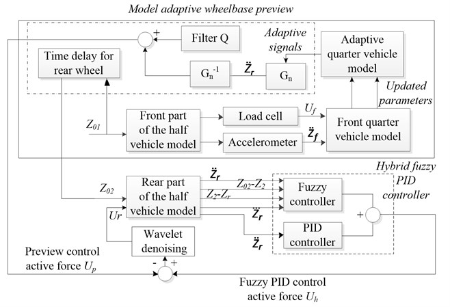
Fig. 2Construction and signal flow of the proposed control method and simulation model
3. Controller design
The overall controller design is shown in Fig. 2, which consists of hybrid fuzzy-PID controller, model adaptive wheelbase preview model and wavelet denoising filter. The detailed design of each module is presented in the following sections.
3.1. Design of hybrid fuzzy-PID controller
The fuzzy and PID control can be used in two different situations, which are determined by a threshold. The threshold was set to be 0.5 through a trial and error method. If the signal of rear sprung mass acceleration is smaller than 0.5, (i.e. the low deviations from the reference point), the PID controller is used, otherwise the fuzzy controller takes control action. This control strategy can provide a fast system response and reduce the system overshoot. In fact, these two control strategies are operated independently at any time instance.
Conventional PID control can be described by using a transfer function as:
where represents the controller output force which is produced by a hydraulic actuator, is the position error, , , and denote the proportional gain, integral gain, and derivative gain, respectively; is a transfer function between the active force and the control signal for the hydraulic actuator.
The main function of fuzzy logic control is to deal with uncertain and imprecise problems, and the multiple-control objectives are considered in this work. Linguistic variables (small (S), medium (M), large (L), etc.) are used to represent the domain knowledge, with their membership values lying between 0 and 1. Basically, the proposed fuzzy controller has the following components: a) fuzzification module, which is used to scale and map the measured variables to suitable linguistic variables; b) knowledge-based linguistic control rules, via which the input linguistic variables can trigger some actions with the fuzzy control rules. With this idea, multiple-control objectives can be achieved; c) decision making logic, by which the final fuzzy control action can be produced; and d) defuzzification module, which is used to scale and map the linguistic control variables to a non-fuzzy output to the hydraulic actuator.
In this study, the tire deflection (-), suspension deflection (-), the acceleration of the rear sprung mass and its derivative are the four input variables to the fuzzy controller while the control voltage producing active force is its output. Triangular membership functions are used to represent the different linguistic variables for (-), (-), , and because of its popularity. The linguistic variable sets for , and are all (S, M, B) where S, M, B stand for Small, Medium and Big respectively. Four scaling factors , , and are used for and respectively to map them to the respective universes of discourses. The fuzzy control voltage is determined by using Eq. (14):
In Eq. (14), denotes the fuzzy relation defined in the fuzzy rule base, and is the transfer function between the active force and the control signal. The conventional max-min composition rule of inference is used for achieving the appropriate fuzzy control voltage, . The centroid method is used for defuzzification. In this method, the centroid of each output membership function for each rule is evaluated first and the final control voltage, , is calculated by multiplying the gain with the average of the individual centroid, weighted by their heights as Eq. (15):
3.2. Design of model adaptive wheelbase preview
The model adaptive wheelbase preview approach is composed of an adaptive front quarter vehicle model and a wheelbase preview algorithm. Before the integration of the adaptive quarter vehicle model and the wheelbase preview algorithm, a big concern coming upon is how to ensure that the parameters from the adaptive quarter vehicle model can be effectively transferred to the wheelbase preview controller without any uncertain disturbance. To address this problem, a classical disturbance observer (DOB) is employed inside the wheelbase preview approach. The main function of the DOB is to overcome the disturbance of the signals from the vehicle model and then delivers the necessary signals to the wheelbase preview controller.
In the framework of the adaptive quarter car model, the most important parameters for model update are the real sprung mass acceleration and active force of the front part of the vehicle. To obtain the above two parameters, an accelerometer is placed on the front part of the sprung mass, while a load cell is mounted on the top of the actuator. Then, the two real sensed parameters are sent to a front quarter vehicle model to update the current status of the vehicle timely, and the corresponding updated parameters are then used to construct the adaptive quarter vehicle model. By this way, the relations between the adaptive quarter vehicle model and the DOB can be represented as:
Regarding the wheelbase preview algorithm, the stable signals from DOB are first received by a nominal quarter vehicle model . The role of the wheelbase preview algorithm is to reduce the sprung mass acceleration of the rear part of the vehicle, so has the same structure but different parameters with that of the front quarter vehicle model. Moreover, DOB consists of an inverse transfer function and a filter . From the nominal quarter vehicle model, it can be observed that the hysteresis term is the source of the system nonlinearity. is considered to be an uncertainty or external disturbance to the system. If can be suppressed, the nominal quarter vehicle model will be equivalent to a second-order linear system. In this work, the hysteresis effect is compensated by using the DOB. Thus, as a linear model, the transfer function between the sprung mass acceleration and the active force of the nominal quarter vehicle model is:
and this means the input is the active suspension force , and the output is acceleration .
So, the inverse of the transfer function of Eq. (18) is:
In many cases, the inverse of the transfer function cannot be obtained because the relative degree (the order of the denominator minus the order of the numerator) is negative after applying an inverse operation, and thus cannot be computed. A filter is then adopted to make the DOB proper and positive, so that its inverse can be computed. Such an operation is possible because after the inverse of the transfer function is multiplied by , the relative order of can be nonnegative by letting the relative degree of be equal to or greater than that of . So, the relative degree of the filter should be no less than that of the quarter-car model. Here, the relative degree of the nominal model of the quarter-car suspension is zero, and so the filter is able to start the relative degree from zero. For convenience, this case sets the filter to be 1.
3.3. Design of wavelet denoising filter
The main target of the wavelet denoising filter is to suppress the noisy part of the measured signals. So, the discrete wavelet transform (DWT) is used in this work to discriminate the noisy signal of the state variable . The general wavelet noise filtering procedure can be described as follows [30]: a) Apply wavelet transform to the noisy signal to produce the noisy wavelet coefficients to a suitable level. b) Select appropriate threshold limit at each level and threshold method to remove the noise. c) Conduct inverse wavelet transform of the threshold wavelet coefficients to obtain a filtered signal. Firstly, the DWT can be represented as:
where is a vector with regard to the wavelet transform coefficient, is the matrix of the wavelet filter coefficients and is the discrete signal. In order to effectively and efficiently filter the noise in the state variable, “mother wavelet” must be selected carefully. The mother wavelet can be obtained as:
where is a scaling variable, is a translation variable and is time. The choice of mother wavelet in this work is based on the Pearson’s product-moment coefficient of the original signal and the filtered signal over many tests. Based on the Pearson’s product-moment coefficient, the Daubechies wavelet Db5 is used as the “mother wavelet” in this work.
With selected mother wavelet, the decomposition and reconstruction of the signal can be achieved by Mallat method [31] as:
where is the scaling variable and is the location index. Then, by constraining the , and , an orthogonal decomposition can be achieved. In this work, both the threshold limits and the level of decomposition were set by many simulation trials. The final threshold limits are 5 times of the standard deviation of the wavelet-transformed signal, and the level of decomposition is set to be 3. As a result, the final filtered signal can then be obtained as:
4. Numerical simulation and analysis
In order to verify the performance of the proposed hybrid fuzzy-PID controller with model adaptive wheelbase preview and wavelet denoising filter (FPMWW), the proposed control method and model were implemented in MatLab/Simulink and comparative studies were conducted. To compare the proposed method with other approaches in active suspension control, a SMC method, whose setting refers to [19], is utilized for the same active suspension as the first comparative case. To identify the advantage of the combination of the fuzzy and PID control methods, a single PID controller with model adaptive wheelbase preview and wavelet denoising filter (PMWW) is constructed as the second comparative case. To compare the proposed controller with a typical method, a sole fuzzy control method is also designed in this work as the third comparative case.
In order to comprehensively evaluate the different control strategies to overall performance of the heavy vehicle, four indices regarding ride comfort, road holding capacity, handling capacity and performance of supporting the vehicle static weight, are compared. The first index is the sprung mass acceleration, which can be regarded as the criterion of the ride comfort. In this case, the sprung mass acceleration of both front and rear wheels and are then compared under the four different control strategies. The second index is the tire deflection (TD), which is regarded as the assessment index of the road holding capacity. The tire deflection can be regarded as a crucial evaluation index in terms of the cornering, barking and traction of the vehicle. Since a tire roughly behaves like a spring in response to vertical forces, variations in normal tire load can directly relate to vertical tire deflections of the front and rear suspensions as - and -, respectively. The third index relates to the pitch acceleration, which is an indicator of good handling during accelerating, decelerating, starting and braking of a vehicle. In the half vehicle model, is the pitch acceleration for quantifying the handling capacity of the vehicle. The last index is the suspension deflection (SD), which is associated with the support of the vehicle static weight. In the half vehicle model, it can be quantified in terms of the suspension deflections - and - undergone by the suspension system. The smaller the performance indexes, the better the vehicle performance is.
Moreover, to more distinctively evaluate the control performance of different control strategies, two more assessment indices are set in this work. The first one is the integral absolute error (IAE), which is represented as:
where is a corresponding index with respect to the evaluation performance at time . The smaller the IAE, the better the individual performance is. The other one is the maximum overshoot (MO), which can be computed as the absolute maximum value of the corresponding indices. The smaller the maximum overshoot, the better the performance is. Then, the improvement of the FPMWW, SMC, and PMWW control methods are summarized and compared with the result of the sole fuzzy control method.
4.1. Analysis of different control strategies on shock excitation
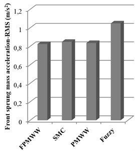
With the road input of shock excitation in Fig. 3, the numerical simulation with different control strategies are conducted based on the system parameters in Tables 1 and 2. Upon completion of the numerical simulation, the root mean square (RMS) values of the performance indices with different control methods are obtained in Figs. 4-7, in which a smaller RMS value can be regarded as a better performance. To further reveal the performance of different methods, a more detailed IAE and MO of the four performance indices with different control strategies are summarized in Table 3.
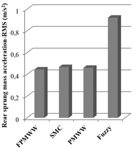
Fig. 4 shows the comparison of the sprung mass acceleration with different control strategies. It can be seen that the proposed FPMWW method obtains the best performance in both the front and rear sprung mass acceleration, whereas the fuzzy method performs the worst in both parts. Moreover, by examining Table 3, the performance of the proposed FPMWW is superior to that of the PMWW method, which proves the advantages of the integration of the fuzzy and PID control methods. Furthermore, the PMWW method exceeds the SMC method in reducing the sprung mass acceleration. The above evidences verify the model adaptive wheelbase preview method and wavelet denoising filter can effectively improve the ride comfort.
Fig. 3Road input of shock excitation
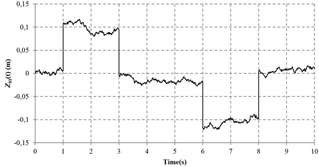
Table 1Parameters of the half vehicle model
Parameter | Unit | Value | Value in the model adaptive wheelbase preview test |
m/s | 20 | 20 | |
mm | 2000 | 2200 | |
mm | 1870 | 1670 | |
Kg | 7200 | 13000 | |
Kg×m2 | 86680 | 125030 | |
Kg | 700 | 700 | |
Kg | 700 | 700 | |
kN/m | 130 | 130 | |
kN/m | 130 | 130 | |
N×s/m | 15200 | 15200 | |
N×s/m | 15200 | 15200 | |
kN/m | 1140 | 1140 | |
kN/m | 1140 | 1140 | |
300 | 300 | ||
0.00001 | 0.00001 | ||
0 | 0 |
Table 2Parameters of the quarter vehicle model
Parameter | Unit | Value | Value in the model adaptive wheelbase preview test |
Kg | 700 | 700 | |
Kg | 3500 | 5720 | |
kN/m | 1140 | 1140 | |
kN/m | 130 | 130 | |
N×s/m | 15200 | 15200 |
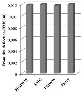
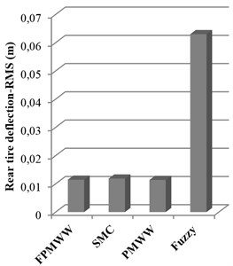
Fig. 5 demonstrates the comparison of the tire deflection with different control strategies. It can be concluded from Fig. 5 that all the control methods hold nearly the same performance in front tire deflection, whereas fuzzy control method behaves the worse road holding capacity in the rear suspension. By examining Table 3, it can be also found that the PMWW method outperforms the other methods in both front and rear tire deflections, but not very obvious as compared with the proposed FPMWW method. In addition, the proposed FPMWW method obtains the same MO as the PMWW method, which also proves the effectiveness of the proposed method.
Table 3Performance evaluation on shock excitation road with different control strategies
Item | FPMWW | SMC | PMWW | FC | ||||||||
IAE | MO | Impr. * | IAE | MO | Impr. * | IAE | MO | Impr. * | IAE | MO | ||
Acc. | F | 880.41 | 5.557 | 34.60 % | 906.82 | 5.724 | 32.64 % | 881.92 | 5.679 | 34.49 % | 1346.17 | 6.084 |
R | 589.84 | 2.787 | 47.53 % | 619.33 | 2.926 | 44.91 % | 611.99 | 2.880 | 45.56 % | 1124.15 | 5.655 | |
TD | F | 10.35 | 0.102 | 11.31 % | 10.56 | 0.104 | 9.50 % | 10.19 | 0.102 | 12.68 % | 11.67 | 0.104 |
R | 9.48 | 0.102 | 90.66 % | 9.81 | 0.106 | 90.33 % | 9.40 | 0.102 | 90.73 % | 101.45 | 0.140 | |
Pitch Acc. | 150.36 | 0.005 | 76.21 % | 160.89 | 0.884 | 74.54 % | 583.45 | 3.227 | 7.67 % | 631.94 | 3.383 | |
SD | F | 41.57 | 0.127 | 28.20 % | 42.61 | 0.130 | 26.41 % | 40.04 | 0.125 | 30.84 % | 57.90 | 0.131 |
R | 32.55 | 0.120 | 77.34 % | 35.48 | 0.130 | 75.31 % | 31.33 | 0.116 | 78.19 % | 143.66 | 0.232 | |
Remark: Bold item means the best result *Impr. means the improvement of IAE as compared with fuzzy controller | ||||||||||||
Fig. 4RMS values of sprung mass acceleration with different controllers under shock road excitation
a) Front sprung mass acceleration
b) Rear sprung mass acceleration
Fig. 5RMS values of tire deflection with different controllers under shock road excitation
a) Front tire deflection
b) Rear tire deflection
Fig. 6 illustrates the pitch acceleration of the vehicle body with different control strategies. It is manifest that the proposed FPMWW and SMC methods are acceptable in maintaining small pitch acceleration, while the PMWW and the fuzzy control methods behave rather worse. Table 3 also shows that the IAE value and MO of the pitch acceleration with the proposed FPMWW method outperforms the other control methods.
Fig. 7 depicts the suspension deflections with different control strategies. With the summarized data in Table 3, it can be found that the PMWW method is the best in terms of reduction of the front and rear suspension deflections, with an improvement of 30.84 % and 78.19 % respectively as compared with the fuzzy control method, but it does not surpass the proposed FPMWW method too much. Besides, the fuzzy control method performs the worse in the rear suspension deflection, which is far from satisfaction for a heavy vehicle. Overall, the above results show that the proposed FPMWW method is effective under shock excitation.
Fig. 6RMS values of pitch acceleration with different controllers under shock road excitation
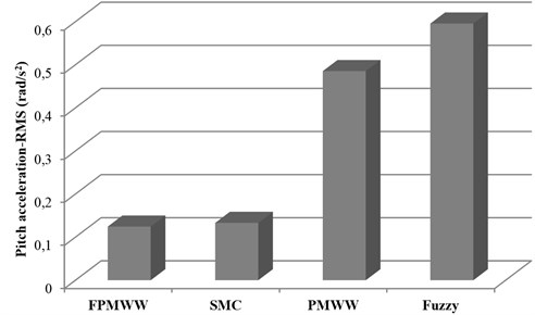
Fig. 7RMS values of suspension deflection with different controllers under shock road excitation
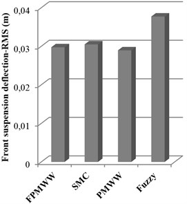
a) Front suspension deflection
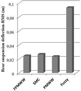
b) Rear suspension deflection
4.2. Analysis of model adaptive wheelbase preview method
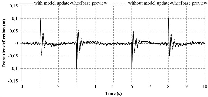
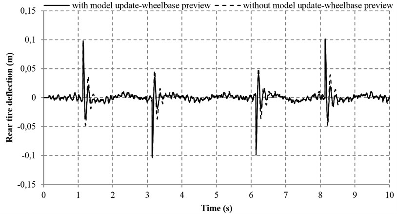
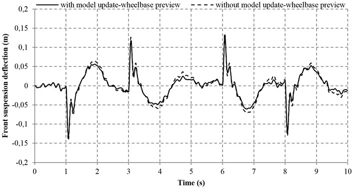
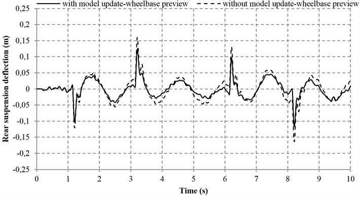
This test mainly exams the effectiveness of the wheelbase preview method with the consideration of updatable vehicle model. The model adaptive method is accomplished by receiving the variation of the updated load signal that is sensed by the load cell. In the test, the mass of the vehicle body is increased from 7200 kg to 13000 kg (see Table 1), and then the front sprung mass is changed from 3500 kg to 5720 kg (see Table 2) which is detected by the load cell. The value of 5720 kg in Table 2 implies that the updated model information is introduced in the process of wheelbase preview. In this test, the road input is also the shock excitation and the test period is 10 seconds. The parameters of the front quarter vehicle with model update can be found in Table 2.
Figs. 8-11 concisely indicate the performance of the proposed controller with and without model adaptive wheelbase preview consideration. It is distinct that the four indices used for quantifying the vehicle performance are improved at a certain degree.
Fig. 8Sprung mass acceleration with and without model adaptive wheelbase preview
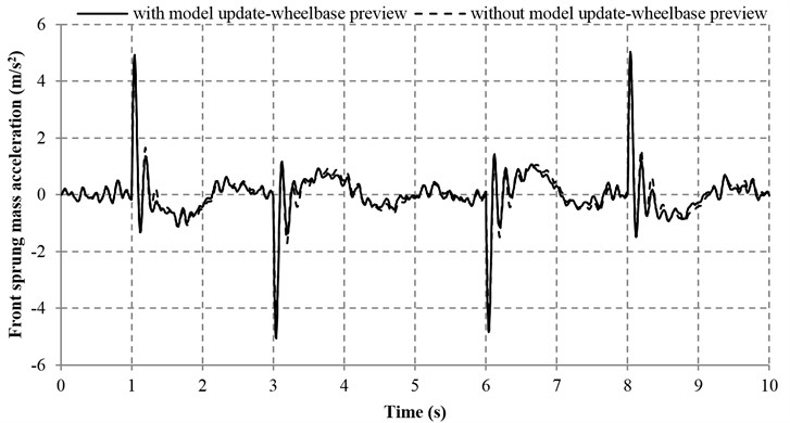
a) Front sprung mass acceleration
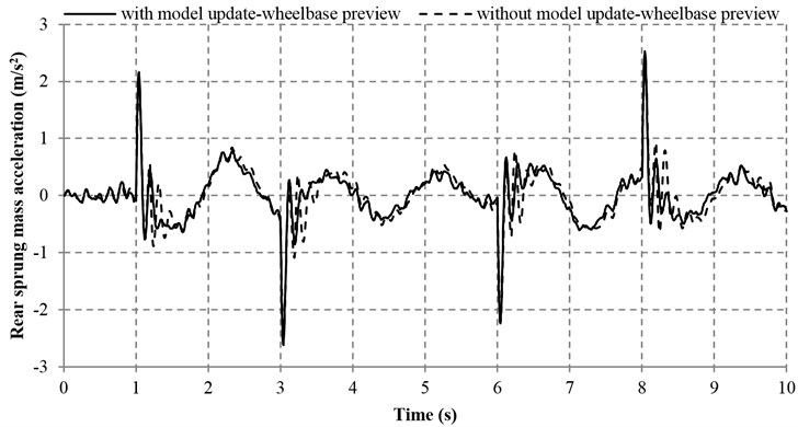
b) Rear sprung mass acceleration
Table 4Performance evaluation of the proposed controller with and without model adaptive wheelbase preview
Item | With model adaptive wheelbase preview | Without model adaptive wheelbase preview | ||||
IAE | MO | Impr. | IAE | MO | ||
Acc. | F | 913.14 | 5.069 | 5.31 % | 964.37 | 4.445 |
R | 614.94 | 2.617 | 8.99 % | 675.71 | 2.455 | |
TD | F | 11.70 | 0.102 | 16.21 % | 13.96 | 0.102 |
R | 9.94 | 0.102 | 22.49 % | 12.83 | 0.105 | |
Pitch Acc. | 150.63 | 0.713 | 9.84 % | 167.07 | 0.608 | |
SD | F | 46.58 | 0.132 | 14.17 % | 54.27 | 0.142 |
R | 40.27 | 0.125 | 28.03 % | 55.95 | 0.164 | |
Remark: Bold item means the best result | ||||||
Table 4 reveals that the sprung mass acceleration, the tire deflections, the pitch acceleration and the suspension deflections in both the front and rear parts of the vehicle can be improved by the model adaptive wheelbase preview method. With this method, the IAE values of the tire and suspension deflections in the front and rear parts of the vehicle are significantly decreased by 16.21 %, 22.49 %, 14.17 % and 28.03 %, respectively. In addition, the IAE values of the front and rear sprung mass acceleration, as well as the pitch acceleration are reduced by 5.31 %, 8.99 % and 9.84 % respectively, which are also in a satisfactory range. However, the maximum overshoot of sprung mass acceleration and pitch acceleration with model adaptive wheelbase preview are increased as compared with that without model adaptive wheelbase preview. Nevertheless, the increase of the aforesaid maximum overshoot is very small and viewed as a random phenomenon, which is insignificant to the general performance of vehicle. Overall, the aforesaid results demonstrate that the proposed model adaptive wheelbase preview method is effective.
Fig. 9Tire deflections with and without model adaptive wheelbase preview
a) Front tire deflection
b) Rear tire deflection
Fig. 10Pitch acceleration with and without model adaptive wheelbase preview
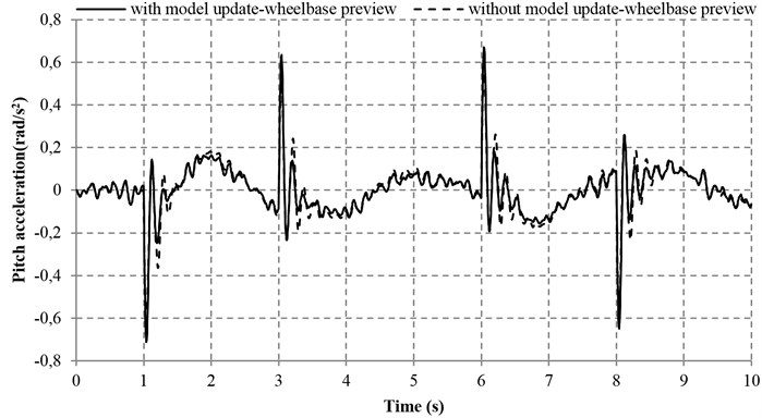
Fig. 11Suspension deflections with and without model adaptive wheelbase preview
a) Front suspension deflection
b) Rear suspension deflection
4.3. Analysis of wavelet denoising filter
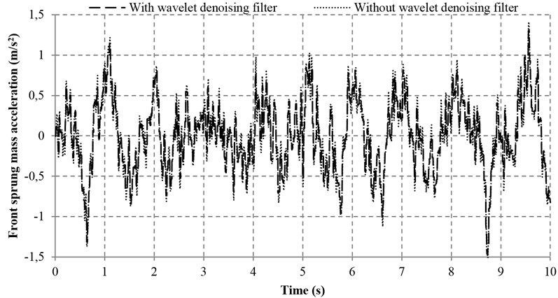
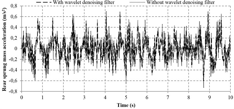
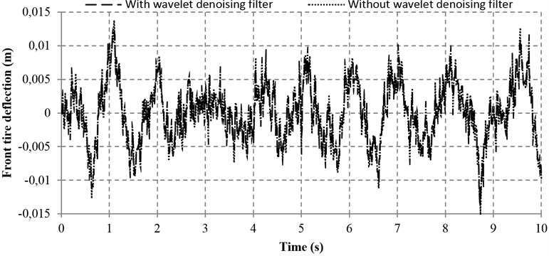
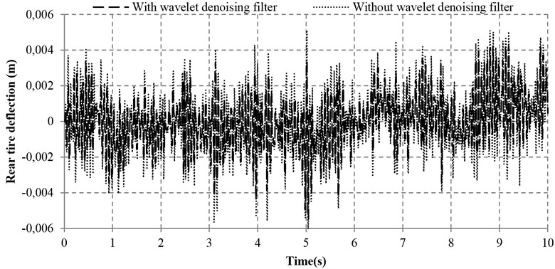
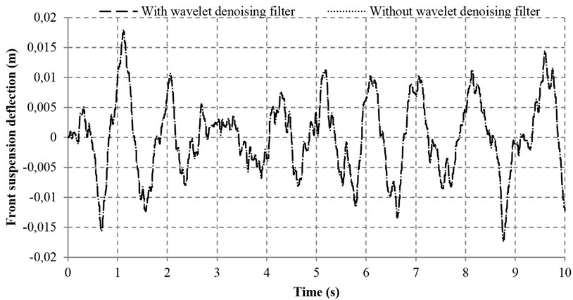
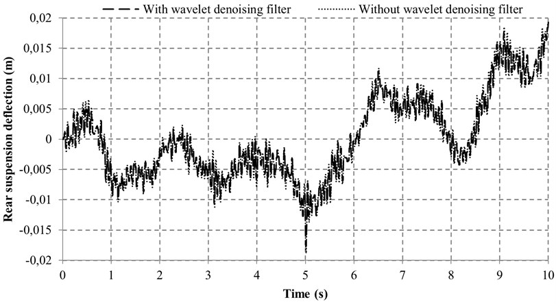
To examine the effectiveness of the wavelet denoising filter, a test was conducted based on the proposed controller with and without the wavelet denoising filter simultaneously. Apart from the noise disturbance from the vibration excitation of the road input (Fig. 12), an additional noise is also introduced (with 0.005 m/s2 Hz) so that the denoising performance of the proposed wavelet method can be greatly validated. Figs. 13-16 reveal the four performance indices with and without wavelet denoising filter. It can be seen clearly from Fig. 13 that the ride comforts of the front and rear suspensions are both improved and the noise disturbance are dramatically reduced. At the same time, it can also be found in Figs. 14 and 15 that the proposed controller with wavelet denoising filter can reduce the noise disturbance and improve the corresponding vehicle performances to some extents. In addition, the control performance with wavelet denoising filter in suspension deflection seems the same as that of without wavelet denoising filter, as shown in Fig. 16.
Fig. 12Road input of vibration excitation
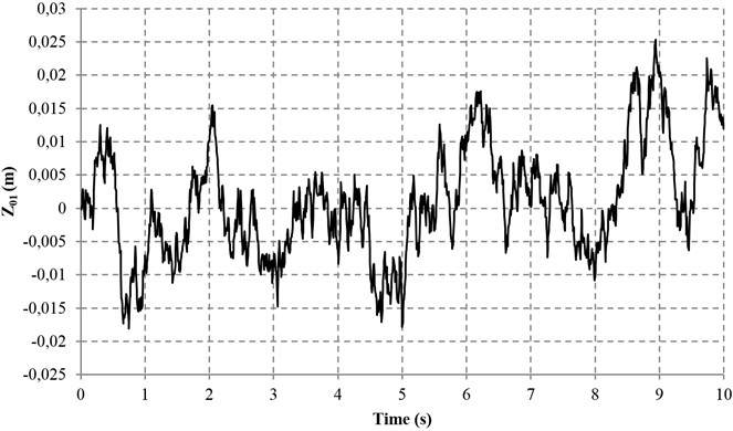
Table 5Performance evaluation of the proposed controller with and without wavelet denoising filter
Item | With wavelet denoising filter | Without wavelet denoising filter | ||||
IAE | MO | Impr. * | IAE | MO | ||
Acc. | F | 617.5434 | 1.3144 | 2.98 % | 636.5154 | 1.3913 |
R | 285.4447 | 0.5763 | 9.52 % | 315.4850 | 0.6585 | |
TD | F | 6.1592 | 0.0122 | 2.29 % | 6.3035 | 0.0134 |
R | 2.1637 | 0.0049 | 15.55 % | 2.5621 | 0.0054 | |
Pitch Acc. | 131.6327 | 0.2514 | 0.84 % | 132.7500 | 0.2540 | |
SD | F | 9.0028 | 0.0158 | 0.14 % | 9.0156 | 0.0162 |
R | 10.2158 | 0.0173 | 0.46 % | 10.2627 | 0.0173 | |
Remark: Bold item means the best result | ||||||
The according data of the performance evaluation of the proposed controller with and without wavelet denoising filter is summarized in Table 5. As compared with the system without wavelet denoising filter, the sprung mass acceleration and tire deflection of the front part of the vehicle are reduced by 2.98 and 2.29 %, respectively. It is also noted that the sprung mass acceleration and tire deflection of the rear part of the vehicle are remarkably reduced by 9.52 % and 15.55 %, respectively. Moreover, the pitch acceleration and the front and rear suspension deflections are all reduced slightly by 0.84 %, 0.14 % and 0.46 %, respectively. In a nutshell, the promising results show that the wavelet denoising filter is effective.
Fig. 13Sprung mass acceleration with and without wavelet denoising filter
a) Front sprung mass acceleration
b) Rear sprung mass acceleration
5. Conclusions
This work presents a novel hybrid fuzzy PID controller with model adaptive wheelbase preview and wavelet denoising filter. The integrated method is successfully applied to an active suspension system of the heavy vehicle. The unconnected half vehicle model and shock and vibration road excitation profiles are successful constructed in this work. With a shock excitation road input, the proposed controller is proved to be effective in improving the vehicle performance in terms of ride comfort and handling capacity. Meanwhile, the proposed FPMWW controller is also capable of increasing the road holding capacity and supporting capacity of the vehicle static weight with an acceptable improvement. In addition, by examining the performance of the model adaptive wheelbase preview, it can be concluded that the model adaptive wheelbase preview method contributes a lot to improve the concerned vehicle performance. At the same time, the wavelet denoising filter is also shown to be an effective way to ensure the system robustness against noise and improve the vehicle performance. As a final conclusion, the proposed approach provides a cost-effective way to improve the performance of heavy vehicles with active suspension systems.
Fig. 14Tire deflections with and without wavelet denoising filter
a) Front tire deflection
b) Rear tire deflection
Fig. 15Pitch acceleration with and without wavelet denoising filter
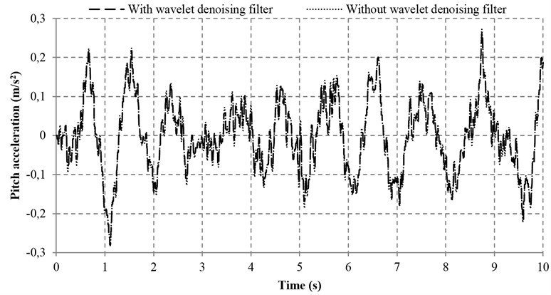
Fig. 16Suspension deflections with and without wavelet denoising filter
a) Front suspension deflection
b) Rear suspension deflection
References
-
RajamaniR. Vehicle Dynamics and Control. Second Edition, Springer, 2012, p. 498.
-
Cao D. P., Rakheja S., SuC. Y. Heavy vehicle pitch dynamics and suspension tuning. Part I: unconnected suspension. Vehicle System Dynamics, Vol. 46, 2008, p. 931-953.
-
Yarmohamadi H., Berbyuk V.Kinematic and dynamic analysis of a heavy truck with individual front suspension. Vehicle System Dynamics, Vol. 51, 2013, p. 877-905.
-
Imine H., Fridman L. M., Madani T. Steering control for rollover avoidance of heavy vehicles. IEEE Transactions on Vehicular Technology, Vol. 61, 2012, p. 3499-3509.
-
Cao D. P., Song X. B., AhmadianM. Editors’ perspectives: road vehicle suspension design, dynamics, and control. Vehicle System Dynamics, Vol. 49, 2011, p. 3-28.
-
Choi S. B., Lee H. S., ParkY. P. H (infinity) control performance of a full-vehicle suspension featuring magnetorheological dampers. Vehicle System Dynamics, Vol. 38, 2002, p. 341-360.
-
Zareh S. H., Sarrafan A., Khayyat A. A. A., ZabihollahA. Intelligent semi-active vibration control of eleven degrees of freedom suspension system using magnetorheological dampers. Journal of Mechanical Science and Technology, Vol. 26, 2012, p. 323-334.
-
Yoshimura T., Kume A., Kurimoto M., HinoJ. Construction of an active suspension system of a quarter car model using the concept of sliding mode control. Journal of Sound and Vibration, Vol. 239, 2001, p. 187-199.
-
BenderE. K. Optimum linear preview control with application to vehicle suspension. Journal of Fluids Engineering, Vol. 90, 1968, p. 213-221.
-
Senthil S., NarayananS. Optimal preview control of a two-dof vehicle model using stochastic optimal control theory. Vehicle System Dynamics, Vol. 25, 1996, p. 413-430.
-
Marzbanrad J., Ahmadi G., Zohoor H., HojjatY. Stochastic optimal preview control of a vehicle suspension. Journal of Sound and Vibration, Vol. 275, 2004, p. 973-990.
-
Pilbeam C., SharpR. S. On the preview control of limited bandwith vehicel suspensions. Proceedings of the Institution of Mechanical Engineers, Part D: Journal of Automobile Engineering, Vol. 207, 1993, p. 185-193.
-
Gohrle C., Schindler A., Wagner A., SawodnyO. Design and vehicle implementation of preview active suspension controllers. IEEE Transactions on Control Systems Technology, Vol. 22, 2014, p. 1135-1142.
-
Xie Z. C., Wong P. K., Zhao J., Xu T., Wong K. I., WongH. C. A noise-insensitive semi-active air suspension for heavy-duty vehicles with an integrated fuzzy-wheelbase preview control. Mathematical Problems in Engineering, Vol. 2013, 2013.
-
Youn I., Tchamna R., Lee S. H., Uddin N., Lyu S. K., TomizukaM. Preview suspension control for a full tracked vehicle. International Journal of Automotive Technology, Vol. 15, 2014, p. 399-410.
-
Ieluzzi M., Turco P., MontiglioM. Development of a heavy truck semi-active suspension control. Control Engineering Practice, Vol. 14, 2006, p. 305-312.
-
He J., Chen Y. K., Zhao C. H., Qi Z. G., RenX. H. Heavy truck suspension optimisation based on modified skyhook damping control. International Journal of Heavy Vehicle Systems, Vol. 18, 2011, p. 161-178.
-
Li H. Y., Jing X. J., KarimiH. R. Output-feedback-based H-infinity control for vehicle suspension systems with control delay. IEEE Transactions on Industrial Electronics, Vol. 61, 2014, p. 436-446.
-
Alves U. N. L. T., Garcia J. P. F., Teixeira M. C. M., Garcia S. C., Rodrigues F. B. Sliding mode control for active suspension system with data acquisition delay. Mathematical Problems in Engineering, Vol. 2014, 2014.
-
Gohrle C., Schindler A., Wagner A., SawodnyO. Model predictive control of semi-active and active suspension systems with available road preview. Proceedings of 2013 European Control Conference (ECC), 2013, p. 1499-1504.
-
Suebsomran A. Adaptive neural network control of electromagnetic suspension system. International Journal of Robotics and Automation, Vol. 29, 2014, p. 144-154.
-
Cao J. T., Li P., Liu H. H. An interval fuzzy controller for vehicle active suspension systems. IEEE Transactions on Intelligent Transportation Systems, Vol. 11, 2010, p. 885-895.
-
Chiou J. S., LiuM. T. Using fuzzy logic controller and evolutionary genetic algorithm for automotive active suspension system. International Journal of Automotive Technology, Vol. 10, 2009, p. 703-710.
-
Yagiz N., Hacioglu Y., Taskin Y. Fuzzy sliding-mode control of active suspensions. IEEE Transactions on Industrial Electronics, Vol. 55, 2008, p. 3883-3890.
-
Moradi M., FekihA. Adaptive PID-sliding-mode fault-tolerant control approach for vehicle suspension systems subject to actuator faults. IEEE Transactions on Vehicular Technology, Vol. 63, 2014, p. 1041-1054.
-
Demir O., Keskin I., CetinS. Modeling and control of a nonlinear half-vehicle suspension system: a hybrid fuzzy logic approach. Nonlinear Dynamics, Vol. 67, 2012, p. 2139-2151.
-
Grossmann A., MorletJ. Decomposition of hardy functions into square integrable wavelets of constant shape. SIAM Journal on Mathematical Analysis, Vol. 15, 1984, p. 723-736.
-
Chen X., LiJ. Noise reduction for ultrasonic Lamb wave signals by empirical mode decomposition and wavelet transform. Journal of Vibroengineering, Vol. 15, 2013, p. 1157-1165.
-
Vong C. M., Wong P. K., Ip W. F., ChiuC. C. Simultaneous-fault diagnosis of automotive engine ignition systems using prior domain knowledge and relevance vector machine. Mathematical Problems in Engineering, Vol. 2013, 2013.
-
Shim I., Soraghan J. J., Siew W. H. Detection of PD utilizing digital signal processing methods – Part 3: Open-loop noise reduction. IEEE Electrical Insulation Magazine, Vol. 17, 2001, p. 6-13.
-
MallatS. G. A theory for multiresolution signal decomposition – the wavelet representation. IEEE Transactions on Pattern Analysis and Machine Intelligence, Vol. 11, 1989, p. 674-693.
About this article
The research is supported by the University of Macau Research Grant, Grant Nos. MYRG081(Y1-L2)-FST12-WPK and MYRG077(Y1-L2)FST13-WPK.
