Abstract
The objective of this paper is to study the reasonable stiffness of rubber mat layer of vibration reduction slab track and configuration of rubber mat layer of transition section slab tack between vibration reduction section and normal section in high-speed tunnel. Based on achievements of the related studies, a high-speed train, slab track and tunnel finite element coupling dynamic model was established, and corresponding program was developed with MATLAB and verified by in situ measured data. The dynamic responses of slab track under moving high-speed train with different vibration reduction configurations and transition arrangements in Shiziyang tunnel of Guangzhou-Hong Kong high-speed railway line in China were analyzed. The study shows that: the rubber mat layer under the slab of slab track can greatly reduce the tunnel vibration, but the slab bending moment and the rail vertical displacement will increase, so the stiffness of rubber mat layer under the slab of slab track in tunnel of high-speed railway line should not be too low; the stiffness of rubber mat layer of slab track in tunnel of Guangzhou-Hong Kong line is controlled by the rail vertical displacement, and the stiffness value of 0.04 N/mm3 is reasonable; the vibration and dynamic stress of slab track can be improved greatly by setting transition section between vibration reduction slab track and ordinary slab track, and the design of transition section slab track in tunnel of Guangzhou-Hong Kong line is reasonable.
1. Introduction
Slab track is a modern railway technology. By using slab track, stability of track can be enhanced, comfort and safety operation of high-speed train can be ensured, and the change rate of track geometry and maintenance work can also be greatly reduced because of the cancellation of the ballast which can cause residual track deformation easily. With the development of slab track technology, slab track has been widely used in high-speed railway in the world, such as German, Japanese and China et al. [1].
Though slab track has many advantages, its stiffness is greater than ballast track, so its influence on environmental vibration is more serious than that of ballast track does in normal conditions. Without vibration reduction measures, it cannot be used directly in some sections of high-speed railway which have special requirements for environmental vibration, for example, the Shiziyang tunnel under the Shiziyang River on Guangzhou-Hong Kong high-speed railway line. The maximum water depth of Shiziyang River is 26.6 m, the maximum water width of Shiziyang River is 3300 m. The foundation of Shiziyang tunnel under the Shiziyang River consists mainly of sand and soft soil, which is very sensitive to environmental vibration.
At present, lots of research work has been done on the dynamic characteristics of slab track of high-speed railway. However, most of these researches are aimed at ordinary slab track structure in normal line [2-9]. Few studies have been made on the dynamic characteristics of vibration reduction slab track structure in vibration reduction section of high-speed railway line, as well as the dynamic characteristics of slab track structure of the transition section between the vibration reduction and normal section of high-speed railway line. Furthermore, former studies mainly concentrated on the vibration characteristic of the coupling system, and few studies considered the dynamic stress of the slab track, which is a key factor for the fatigue failure of slab track. Thirdly, only middle-long random track irregularities, whose wavelength is longer than 1m, is taken into account in the vibration reduction simulation studies, while short-wave random track irregularities, whose wave length is less than 1 m and which has significant influence on the dynamic response of track structure, is not taken into account.
In this paper, based on achievements of the related studies, a high-speed train, slab track and tunnel finite element dynamic model, which takes both short wavelength random track irregularities and middle-long wavelength random track irregularities into account, was established. The corresponding program was developed with MATLAB self-developed program and verified by field test results. With the established dynamic model, taking high-speed trains passing vibration reduction section and adjacent transition section of slab track in Shiziyang tunnel of Guangzhou-Hong Kong line as an example, considering both vibration characteristic of system and dynamic stress of the slab track, the reasonable stiffness value of rubber mat layer under the slab in vibration reduction section of Shiziyang tunnel of Guangzhou-Hong Kong line is studied. By comparing dynamic characteristic of high-speed train-slab track-tunnel system with or without transition section between vibration reduction slab track section and ordinary slab track section, the reasonability of transition section design is verified.
2. Dynamic model
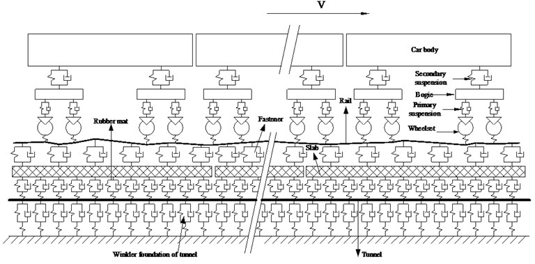
A schematic describing the dynamic model for a high-speed train traveling on a slab track in a tunnel at a constant speed along the longitudinal direction is shown in Fig. 1.
The model consists of four sub-models, namely, the high-speed train, the slab track-tunnel, wheel-rail interaction, and track irregularity sub-models. The high-speed train sub-model is established based on multi-rigid-body dynamics theory, and the slab track-tunnel sub-model is established based on finite element method. The high-speed train sub-model and slab track-tunnel sub-model are coupled through wheel-rail interaction sub-model considering track irregularities. The four sub-models are explained as follows.
Fig. 1Schematic of the coupling dynamic model
2.1. High-speed train sub-model
As shown in Fig. 1, the high-speed train sub-model consists of a series of identical four-wheel high-speed vehicles. Each vehicle of the train is modeled as a multi-rigid-body system including a car body, two bogie frames, four wheel-sets and the connection components. The connections between the bogie frame and the wheel-set are characterized by spring-dampers, named the primary suspension system. The connection between the car body and the bogie frame are characterized by spring-dampers, named the secondary suspension system. The springs are all with linear property, and the dampers are all with viscous property. The car body and each of the two bogie frames have vertical and pitch degrees of freedom (DOF), each of the four wheels has vertical and pitch DOF. Each vehicle of the high-speed train sub-model has 10 DOF.
2.2. Slab track-tunnel sub-model
The 3D slab track-tunnel-soil sub-model using volume elements to simulate the slab, tunnel, and surrounding soil can reflect the dynamic characteristics of the slab track-tunnel-soil sub-system. However, the simulation is extremely time-consuming because long model length, small mesh size and small simulation time step are needed in the simulation of a moving high-speed train along the rail with random irregularity of track in this study.
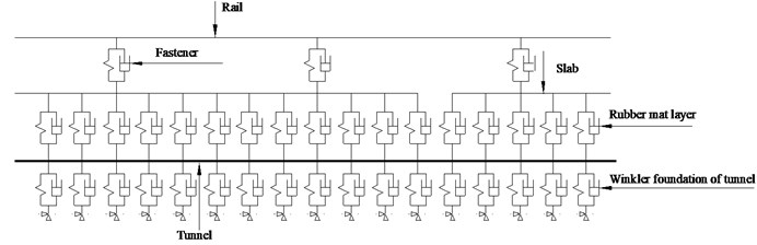
In order to reduce the calculation time, a 2D slab track-tunnel sub-model is used. The sub-model is shown in Fig. 2. The rail, slab, and tunnel are simulated by Bernoulli-Euler beam elements, while fasteners which connect rail and slab, rubber mat layer which connects slab and tunnel, as well as the Winkler foundation of the tunnel are simulated by linear spring-damper elements.
Fig. 22D slab track-tunnel dynamic sub-model
A sophisticated 3D slab track-tunnel-soil model (Fig. 3) is used to determine the equivalent stiffness of the Winkler foundation of the tunnel. In the 3D slab track-tunnel-soil model, the rail is simulated by Bernoulli-Euler beam elements; the slab, rubber mat layer, tunnel, and soil are simulated by volume elements; the fasteners are simulated by linear spring-damper elements.
Fig. 3Sophisticated 3D slab track-tunnel-soil model

a) Cross-section graph
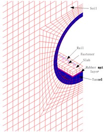
b) Enlarged graph
Static train loads are respectively applied on the 2D slab track-tunnel sub-model shown in Fig. 2 and 3D slab track-tunnel-soil model shown in Fig. 3 to determine the equivalent Winkler foundation stiffness of the tunnel of 2D slab track-tunnel sub-model. If the relative error between the maximum vertical displacement of tunnel in the 2D slab track-tunnel sub-model and that of the 3D slab track-tunnel-soil model is less than 10-6, the equivalent Winkler foundation stiffness has been found. Otherwise, the equivalent stiffness value should be modified until the above requirement can be met.
By different settings of the stiffness of rubber mat layer between slab and tunnel, the slab track of the vibration reduction section at the normal section and the transition section can all be modeled easily in the 2D slab track-tunnel sub-model shown in Fig. 2.
2.3. Wheel-rail interaction model
The wheel-rail interaction model is the same as the model given in reference [10]. The vertical force between wheel and rail is determined by the Hertz nonlinear contact theory considering the track irregularity as follows:
where is the wheel-rail contact force under the th wheel at time , is the wheel-rail contact constant, is the displacement of the th wheel at time , is the rail displacement under the th wheel at time , and is the track irregularity under the th wheel at time .
2.4. Track irregularity model
Because of the lack of track spectrum of high-speed railway in China, low interference spectrum of the German high-speed railway, which is widely used as middle-long wavelength random track irregularity spectrum for high-speed railway all around the world, is used to generate the samples of middle-long wavelength random track irregularity.
The expression of low interference spectrum of the German high-speed railway is as follows:
where is power spectral density, is spatial frequency, is the roughness constant and its value is 4.032×10⁻⁷ m rad, and are cutoff frequency, the value of is 0.8246 rad/m, the value of is 0.0206 rad/m.
The low interference spectrum of the German high-speed railway is formed according to the measured track irregularities (wavelengths are more than 1 m) which are automatically measured by the track geometry recording car running on the track. However, the short wavelength random track irregularities are not well considered in the German's low interference spectrum. According to author and other researchers work, short wave random track irregularities (wavelengths between 0.01 m and 1 m) have great influence on dynamic characteristics of slab track
To consider the influence of short wave random track irregularities on dynamic characteristics of slab track, not only the middle-long wavelength random track irregularity but also the short wavelength random track irregularity were taken into account.
Sato spectrum [11], which is widely used in the fields such as high-frequency wheel-rail contact forces [12], wheel-rail rolling noise [13-14], and wheel-rail wear [15], is used as track irregularity spectrum to generate short wavelength random track irregularities. The expression is as follows:
where is power spectral density, is spatial frequency, is the roughness constant and its value is 4.15×10⁻⁸ m.rad-5.0×10⁻⁷ m.rad.
According to measured rolling noise data of Qinhuangdao-Shenyang line, the value of is suggested to be 3.15×10⁻⁷ m.rad in reference [16].
3. Vibration equations of the coupling dynamic system
Using the principle of total potential energy with the stationary value in elastic system dynamics presented by Zeng [17], one can derive the vibration equation of the high-speed train, slab track and tunnel coupling dynamic model. The equation can be written in matrix form as follows:
where, , , and denote the acceleration, velocity, and displacement vectors for the DOF of the high-speed train sub-system, respectively; , , and denote the acceleration, velocity, and displacement vectors for the DOF of the slab track-tunnel sub-system, respectively; , , and denote the mass, damping, and stiffness matrices of the high-speed train sub-system, respectively; , , and denote the mass, damping, and stiffness matrices of the slab track-tunnel sub-system, respectively; denotes the gravity sub-load vector of the high-speed train sub-system; and denote the sub-load vector of the wheel-rail interaction forces on high-speed train sub-system and slab track-tunnel sub-system, respectively.
Detailed expressions of the stiffness matrix, mass matrix, damping matrix, and load vector of a single vehicle of the high-speed train sub-model can be founded in reference [10]. Likewise, detailed procedures for obtaining the stiffness matrix, mass matrix, damping matrix, and load vector of the slab track-tunnel sub-system can be found in reference [18]. Solution procedures for the vibration equation of the coupled system are as follows.
1) At time 0, the static displacement of the coupled system under the combined effect of gravity load of vehicles and track irregularity is calculated and used as the initial value for the dynamic coupled system.
2) When time 0, using the wheel-rail interaction model considering the track irregularity Eq. (1) and an iteration procedure as described in reference [10], the displacement, velocity, and acceleration of each DOF of the coupled system, as well as the wheel-rail interaction forces are calculated. Then, the force of each spring-damping element and the bending moment of each beam element can also be calculated. It should be mentioned that the convergence of the wheel-rail interaction force must be ensured during each time step.
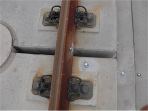
Fig. 4Arrangement of in-situ acceleration sensors
4. Verification of coupling dynamic model
In situ dynamic response measurement was conducted in the vibration reduction slab track section on tunnel of Guangzhou-Hong Kong line. Acceleration sensors were attached to the end side of the slab as shown in Fig. 4. The measurement is used to obtain the accelerations of rail, slab and tunnel when high-speed train runs through the track at speeds from 110 km/h to 300 km/h. The field measured time-history of acceleration of rail, slab, and tunnel are shown in Fig. 5-Fig. 7 when high-speed train runs through the track at the speed of 300 km/h.
Fig. 5Field measured time-history of acceleration of rail
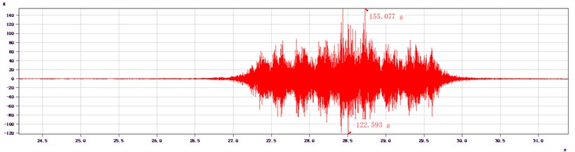
Fig. 6Field measured time-history of acceleration of slab
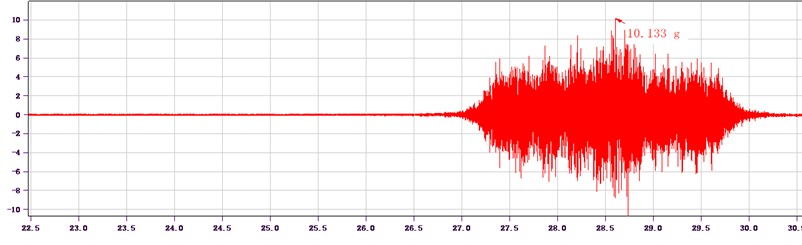
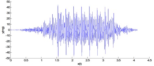
Fig. 7Field measured time-history of acceleration of tunnel
Corresponding numerical simulation was conducted for high-speed train passing vibration reduction section of slab track in Shiziyang tunnel of Guangzhou-Hong Kong high-speed railway line at speed of 300 km/h. The parameters for the high-speed train and those of the slab track-tunnel sub-model are listed in Tables 1 and 2, respectively.
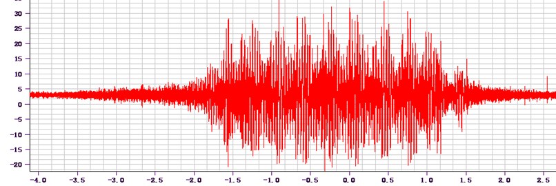
The random track irregularity used in this study is plotted in Fig. 8(a). It is the combination of the sample of middle-long wavelength random track irregularity in Fig. 8(b) and short wavelength random track irregularity in Fig. 8(c).
Time-history curve of maximum acceleration of rail, slab and tunnel calculated by self-developed MATLAB program are shown in Fig. 9-Fig. 11.
Table 1Parameters for the high-speed train sub-model
Parameter | Unit | Value |
Mass of car body | kg | 42400 |
Mass of bogie | kg | 3400 |
Mass of wheelset | kg | 2200 |
Pitch inertia of car body | kg.m2 | 1370000 |
Pitch inertia of bogie | kg.m2 | 3600 |
Vertical damping of primary suspension | N.s.m-1 | 35000 |
Vertical stiffness of primary suspension | N.m-1 | 1040000 |
Vertical damping of secondary suspension | N.s.m-1 | 35000 |
Vertical stiffness of secondary suspension | N.m-1 | 400000 |
Wheelbase | m | 2.5 |
Distance between center of front bogie and center of rear bogie | m | 17.375 |
Table 2Parameters for the slab track-tunnel sub-model
Parameter | Unit | Value |
Section area of rail | cm2 | 77.45 |
Inertia moment of rail | cm4 | 3217 |
Density of rail | kg.m-3 | 7800 |
Elastic modulus of rail | GPa | 210 |
Spacing of fastener | m | 0.625 |
Vertical stiffness of fastener | kN·mm-1 | 30 |
Damping of fastener | kN.s.m-1 | 20 |
Width of slab | m | 2.4 |
Thickness of slab | m | 0.19 |
Elastic modulus of slab | GPa | 36 |
Density of slab | Kg.m-3 | 2500 |
Stiffness of rubber mat layer | MPa/m | 40 |
Section area of tunnel | m2 | 13 |
Inertia moment of tunnel cross-section | m4 | 250 |
Density of tunnel | Kg.m-3 | 2500 |
Dynamic modulus of tunnel foundation | MPa | 60 |
Equivalent Winkler foundation stiffness of tunnel | MPa | 12 |
Fig. 8a) Samples of the combined random track irregularity, b) middle-long wavelength random track irregularity, c) short wavelength random track irregularity
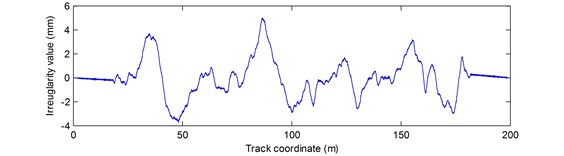
a)
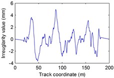
b)
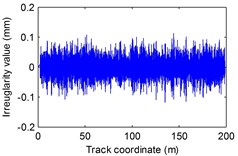
c)
Comparing Fig. 5-Fig. 7 and Fig. 9-Fig. 11, the maximum acceleration of rail, slab, tunnel calculated by self-compiled MATLAB program are 138.245 g, 11.569 g and 48.5 mg, respectively. And the maximum acceleration of rail, slab, and tunnel measured in situ are 155.077 g, 10.133 g and 35 mg, respectively. The results calculated by the self-compiled MATLAB program are agreed with measured data. Considering that the track irregularities used in this study cannot fully agree with the track irregularities of the field environment and that noise signal has influence on the field test result, the discrepancies between the calculated results and measured data are reasonable, which proves that the dynamics response of train-slab track-tunnels coupling system is correct.
Fig. 9Time-history of maximum acceleration of rail calculated by MATLAB
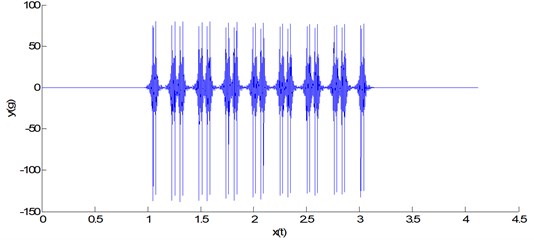
Fig. 10Time-history of maximum acceleration of slab calculated by MATLAB
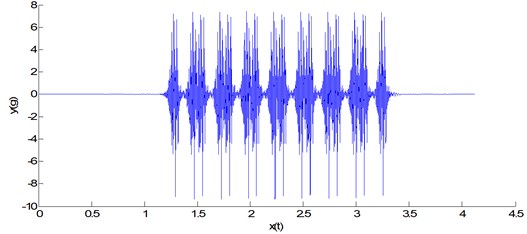
Fig. 11Time-history of maximum vibration acceleration of tunnel calculated by MATLAB
5. Case studies
With the verified high-speed train-slab track-tunnel finite element coupling dynamic model, taking high-speed train passing vibration reduction slab track with different rubber mat stiffness and ordinary slab track in Shiziyang tunnel at speed of 300 km/h as cases, the dynamic characteristic of high-speed train-slab track-tunnel system for 7 cases was theoretical studied and compared. The stiffness value of rubber mat layer for vibration reduction slab track and the stiffness value of cement asphalt (CA) mortar for ordinary slab track for cases 1-7 are listed in Table 3.
With the verified coupling dynamic model, taking high-speed train passing slab track with different configurations of mat layer at speed of 300 km/h as cases, the dynamic characteristic of high-speed train-slab track-tunnel system with or without transition section between vibration reduction slab track and ordinary slab track are studied and compared. The configurations of length and stiffness of mat layer for cases 8-9 are shown in Table 4.
It should be mentioned that except the stiffness value of rubber mat layer for vibration reduction slab track and the stiffness value of CA mortar for ordinary slab track, which are listed in Table 3-4 for different cases, the other calculation parameters are the same as those in Section 4.
The dynamic response of the car body, bogie, wheel-set, rail, fastening, slab, mat layer, tunnel of the coupling system for Cases 1-9 are listed in Table 5.
Table 3The stiffness of rubber mat layer or CA mortar for case 1-7
Case | Type of slab track | Stiffness of rubber mat layer for vibration reduction slab track or CA mortar for ordinary slab track (N/mm3) |
1 | Vibration reduction slab track | 0.01 |
2 | Vibration reduction slab track | 0.02 |
3 | Vibration reduction slab track | 0.04 |
4 | Vibration reduction slab track | 0.06 |
5 | Vibration reduction slab track | 0.08 |
6 | Vibration reduction slab track | 0.1 |
7 | Ordinary slab track | 4 |
Table 4Configurations of mat layer for cases 8-9
Case | Type of slab track | Layout of length of rubber mat layer or CA mortar (m) | Layout of stiffness of rubber mat layer or CA mortar (N/mm3) |
8 | With transition section | 50-50-50-50-50-50-50-50-50 | 4-0.1-0.08-0.06-0.04-0.06-0.08-0.1-4 |
9 | Without transition section | 150-150-150 | 4-0.04-4 |
From the simulation of the case study, the following points can be obtained:
1) The vibration acceleration of tunnel can be reduced greatly with rubber mat layer used under the slab. The lower the stiffness of rubber mat layer is, the smaller the vibration acceleration of tunnel will be.
2) The rail vertical displacement and the slab bending moment increases significantly with rubber mat layer used under the slab. The lower the stiffness of rubber mat layer is, the larger the rail vertical displacement and the slab bending moment will be.
3) According to the relevant codes and regulations, the vertical displacement of rail of high-speed railway above 300 km/h should not be more than 2 mm. Considering the limited value of rail vertical displacement, the stiffness of rubber mat layer of vibration reduction section of Shiziyang tunnel of Guangzhou-Shenzhen-Hong Kong line should not be smaller than 0.04 N/mm3.
4) Comparing with the ordinary slab track, the acceleration of tunnel decreased 16 dB by adopting vibration reduction slab track with 0.04 N/mm3 stiffness of rubber mat layer. The vibration reduction effect of rubber mat layer is excellent.
5) The bending moment of slab increases substantially with rubber mat layer used under the slab, so the strength of slab should be carefully checked to avoid fatigue failure of slab.
6) Without transition section between vibration reduction slab track and ordinary slab track, the pressure force of rubber mat layer, bending moment of slab, pressure and tension force of fastener, and acceleration of slab and tunnel increase substantially. With transition section between vibration reduction slab track and ordinary slab track, dynamic characteristic of slab track and tunnel are excellent, design of transition section between vibration reduction slab track and ordinary slab track in tunnel of Guangzhou-Hong Kong line is reasonable.
Table 5Calculation results for cases 1-9
Case | 1 | 2 | 3 | 4 | 5 | 6 | 7 | 8 | 9 |
Maximum vertical acceleration of wheel-set (m/s2) | 58.37 | 61.09 | 57.64 | 57.01 | 56.91 | 57.05 | 57.22 | 0.48 | 1.07 |
Maximum vertical acceleration of bogie (m/s2) | 4.46 | 5.29 | 5.31 | 5.98 | 6.34 | 6.59 | 6.35 | 0.09 | 0.22 |
Maximum vertical acceleration of car body (m/s2) | 0.43 | 0.41 | 0.42 | 0.42 | 0.42 | 0.42 | 0.42 | 0.00 | 0.13 |
Maximum force of wheel-set (kN) | 145.09 | 147.51 | 145.19 | 143.18 | 144.45 | 143.93 | 143.25 | 83.94 | 90.76 |
Maximum displacement of rail (mm) | 4.37 | 2.97 | 1.94 | 1.77 | 1.65 | 1.57 | 1.24 | 1.76 | 1.85 |
Maximum acceleration of rail (m/s2) | 1354.02 | 1354.03 | 1356.18 | 1349.25 | 1346.97 | 1346.06 | 1354.55 | 29.84 | 35.59 |
Maximum acceleration of slab (m/s2) | 113.88 | 116.89 | 113.49 | 106.76 | 103.82 | 103.58 | 166.75 | 17.47 | 23.04 |
Maximum acceleration of tunnel (m/s2) | 0.21 | 0.28 | 0.48 | 0.71 | 0.81 | 0.86 | 3.11 | 0.10 | 0.15 |
Vibration level of tunnel (dB) | 106.30 | 108.97 | 113.56 | 117.00 | 118.12 | 118.70 | 129.85 | 100.11 | 103.68 |
Effects on vibration suppression (dB) | 23.55 | 20.88 | 16.29 | 12.85 | 11.72 | 11.14 | 0.00 | – | – |
Maximum positive moment of rail (kN.m) | 27.90 | 25.52 | 23.35 | 23.49 | 23.51 | 23.69 | 23.46 | 18.86 | 20.26 |
Maximum negative moment of rail (kN.m) | 14.17 | 10.66 | 11.06 | 11.56 | 11.62 | 11.53 | 12.10 | 8.70 | 10.09 |
Maximum pressure force of fastener (kN) | 47.86 | 47.89 | 47.49 | 48.66 | 49.09 | 48.71 | 49.53 | 31.70 | 37.67 |
Maximum tension force of fastener (kN) | 11.84 | 9.28 | 7.28 | 7.32 | 7.40 | 7.42 | 7.88 | 2.70 | 3.40 |
Maximum positive moment of slab (kN.m/m) | 16.69 | 11.89 | 8.98 | 8.82 | 8.21 | 7.52 | 3.11 | 7.42 | 8.53 |
Maximum negative moment of slab (kN.m/m) | 19.69 | 14.43 | 9.35 | 7.28 | 6.08 | 5.17 | 1.47 | 7.21 | 7.33 |
Maximum compressive stress of rubber mat layer (MPa) | 0.04 | 0.05 | 0.05 | 0.05 | 0.05 | 0.05 | 0.11 | 0.05 | 0.06 |
Maximum compressive displacement of rubber mat layer (mm) | 3.90 | 2.35 | 1.20 | 0.83 | 0.64 | 0.52 | 0.03 | 0.99 | 1.02 |
6. Conclusions
The high-speed train-slab track-tunnel finite element coupling dynamic model was established, and corresponding program was developed with MATLAB program language and verified by in situ measured data. Taking high-speed train passing slab track of vibration reduction section and adjacent transition section on tunnel of Guangzhou-Hong Kong line as an example, dynamic characteristics of high-speed train, slab track and tunnel system was theoretical studied and compared. The main conclusions include:
1) The lower the stiffness of rubber mat layer is, the larger the vertical displacement of rail and the bending moment of slab will be. The stiffness of rubber mat layer of slab track in tunnel of Guangzhou-Hong Kong line is controlled by the rail vertical displacement, and the 0.04 N/mm3 stiffness value for rubber mat layer is reasonable. By using rubber mat layer under the slab, vibration of tunnel can decrease 16 dB, and the effect of vibration reduction of rubber mat layer is excellent.
2) With transition section between vibration reduction slab track and ordinary slab track, vibration and dynamic stress of slab track are excellent. The design of transition section between vibration reduction slab track and ordinary slab track in tunnel of Guangzhou-Hong Kong line is reasonable.
References
-
Hu N., Dai G. L., Bin Y., Liu K. Recent development of design and construction of medium and long span high-speed railway bridges in china. Engineering Structures, Vol. 74, 2014, p. 233-241.
-
Feng Q. S., Lei X. Y., Lian S. L. Vibration analysis of high-speed railway slab track on soil subgrade with geometric irregularities. International Conference on Transportation Engineering, 2009, p. 1287-1292.
-
Steenbergen M. J. M. M., Metrikine A. V., Esveld C. Assessment of design parameters of a slab track railway system from a dynamic viewpoint. Journal of Sound and Vibration, Vol. 306, Issue 1, 2007, p. 361-371.
-
Dai F., Xu G. X., Yang J. B., Liu X. Y. Dynamic performance of unbonded pre-stressed steel bar in CRTS I ballastless slab track under train load. Fourth International Conference on Transportation Engineering, 2013, p. 1765-1770.
-
Lei X. Y., Wang J. Dynamic analysis of the train and slab track coupling system with finite elements in a moving frame of reference. Journal of Vibration and Control, Vol. 20, Issue 9, 2013, p. 1301-1317.
-
Wang P., Xu H., Chen R. Effect of cement asphalt mortar debonding on dynamic properties of CRTS II slab ballastless track. Advances in Materials Science and Engineering, Vol. 47, Issue 2, 2014, p. 1-8.
-
Verbic B. Investigating the dynamic behavior of rigid track. Rail Gazette International, Vol. 153, Issue 9, 1997, p. 585-586.
-
Xu Q. Y., Li B. Study on spatial mechanical characteristic of high-speed railway ballastless slab track on subgrade. Advanced Materials Research, Vol. 503, 2012, p. 1010-1015.
-
Xu Q. Y., Cao Y. F., Zhou X. L. Influence of short-wave random irregularity on vibration characteristic of train-slab track-subgrade system. Journal of Central South University, Science and Technology, Vol. 42, Issue 4, 2011, p. 1105-1110.
-
Lei X. Y., Noda N. A. Analyses of dynamic response of vehicle and track coupling system with random irregularity of track vertical profile. Journal of Sound and Vibration, Vol. 258, Issue 1, 2002, p. 147-165.
-
Sato Y. Study on high-frequency vibration in track operation with high-speed trains. Quarterly Reports, Vol. 18, Issue 3, 1977, p. 109-114.
-
Nielsen J. C. O. High-frequency vertical wheel–rail contact forces – validation of a prediction model by field testing. Wear, Vol. 265, Issue 9, 2008, p. 1465-1471.
-
Thompson D. J. The influence of the contact zone on the excitation of wheel/rail noise. Journal of Sound and Vibration, Vol. 267, Issue 3, 2003, p. 523-535.
-
Hardy A. E. J., Jones R. R. K., Turner S. The influence of real-world rail head roughness on railway noise prediction. Journal of sound and vibration, Vol. 293, Issue 3, 2006, p. 965-974.
-
Nielsen J. C. O. Numerical prediction of rail roughness growth on tangent railway tracks. Journal of Sound and Vibration, Vol. 267, Issue 3, 2003, p. 537-548.
-
Xu Z. S. Prediction and control of wheel/ rail noise for rail transit. Southwest Jiaotong University of China, 2004.
-
Zeng Q. Y. The principle of a stationary value of total potential energy of dynamic system. Huazhong University of Science and Technology, Vol. 28, Issue 1, 2000, p. 1-3.
-
Lou P. Finite element analysis for train-track-bridge interaction system. Archive of Applied Mechanics, Vol. 77, Issue 10, 2007, p. 707-728.
About this article

The works described in this paper are supported by National Natural Science Foundation of China (No. 51178469), the National Science Joint High-speed Railway Foundation of China (No. U1334203) and China Postdoctoral Science Foundation (2014M552158), as well as the State Scholarship Fund of China Scholarship Council (No. 201208430112).
