Abstract
A thermal-vibration test system is established by combining the high-temperature transient heating simulation system and vibration test apparatus, and this system can carry out experimental research on the thermal modal of high-temperature-resistant composite wing structure of hypersonic flight vehicles under high temperature environment with 1100°C. The vibration signals of the composite wing structure in high-temperature environments are transmitted to non-high temperature field by using self-developed extension configurations and then the vibration signals are measured and identified by using ordinary acceleration sensors. Based on a time-frequency joint analysis technique, the experimental data is analyzed and processed to obtain the key vibration characteristic parameters of composite wing structure, such as the natural frequency and mode shapes, in a thermal-vibration coupled environment up to 1100°C. The experimental results provide an important basis for the dynamic performance analysis and safety design of composite wing structure under high-temperature thermal-vibration conditions.
1. Introduction
In the aerospace field, the application of advanced composite materials is an important research interest [1], and some key structural components of high-speed flight vehicles are extensively made of composite materials [2]. Hypersonic flight vehicles can fly at a high speed beyond Mach 5 (Ma > 5). And for a hypersonic flight vehicle in high-speed flight, the thermal environments generated by the aerodynamic heating will be very harsh. The temperatures of the thermal environments that the attitude control structures of hypersonic aircraft, such as the wings and rudders, are subjected to generally exceed 1000°C [3]. Conventional metal materials will be ineffective in harsh environments beyond 1000°C; thus, composite structures capable of withstanding higher temperatures have to be applied in those ultra-high temperature environments. Moreover, during a long flight, the attitude control structures (e.g. wings and rudders) for long-range, high-speed flight vehicles undergo prolonged serious vibration. The high temperature caused by aerodynamic heating changes the mechanical properties of materials and structures, leading to changes in the vibration characteristics of the wings and rudder. These changes have significant impacts on the flutter characteristics and controllability of long-range, high-speed flight vehicles. Therefore, studying the variation of natural frequencies and other dynamic parameters of composite wings and rudders versus temperatures under a force-heat-coupled environment is significant for the reliability design and flight safety of hypersonic flight vehicles.
A lot of scholars have theoretically analyzed and numerically calculated the thermal-vibration properties of aerospace composite structures. Lee et al. [4] analyzed the supersonic flutter characteristics of stiffened laminated plates that were subjected thermal loads by the finite element method. P. Jeyaraj et al. [5] established the finite element modeling of a fiber-reinforced composite plate and calculated the natural frequencies and modal shape of composite plate under various temperatures. Based on the energy principle and variational method, Xia Wei et al. [6] developed vibration control equations for composite panels of aircraft under uniform temperature load and analyzed the effects of thermal environments on the vibration characteristics of composite panels. Andrew M. Brown [7] performed a theoretical analysis and numerical calculation on the natural frequencies and mode shape of the X-34 rocket nozzle. Yiming Fu et al. [8] established governing equations for the motion of fiber-metal laminated beams, which are widely used in the aerospace industry in unsteady temperature fields, and researched the dynamic response of the laminated beams in different thermal environments. So far, theoretical analysis and numerical simulation of the vibration characteristics of composite structures are more common [9-11], whereas experimental studies on heat-vibration coupling in high-temperature environments are rarely reported.
It is very important for the safety design of hypersonic flight vehicles to obtain dynamic structure parameters in extremely high-temperature environments by ground testing. However, measuring the dynamic parameters of a wing structure in a harsh environment, with temperatures as high as a thousand degrees, is extremely difficult. High-temperature acceleration sensors were used in the thermal-vibration test for a C/SiC rudder of an X-37 at the NASA Dryden flight research center (DFRC) in the United States [12]. Because of working temperature limitations for the high-temperature acceleration sensors, the thermal environment was only as high as 482°C for the test at the DFRC. A non-contact method based on a laser vibration measuring technique was applied to carry out a thermal modal test for a rectangular plate at Chungnam National University and the experimental temperature was up to 500°C [13]. Nevertheless, in order to avoid interference with the laser beam by the heating source, only one side of the rectangular plate was heated in the experiment. That was different from the practical thermal condition, in which both sides were heated simultaneously, for the hypersonic aircraft. Researchers at the Harbin Institute of Technology performed a thermal-vibration test for a cantilever plate under 300°C and obtained natural frequencies [14]. So far, no experimental study on thermal modal of composite wings and rudders of hypersonic flight vehicles in extremely high-temperature environments with temperatures exceeding 1000°C has been reported.
In this report, a transient aerodynamic heating simulation system and vibration test setup are combined to establish a thermal-vibration test system that is able to perform experimental research on the thermal modal of a high-temperature-resistant composite wing structure subjected to high temperatures up to 1100°C for hypersonic flight vehicles. Infrared radiation heating arrangements are used to generate controlled, dynamic thermal environments for the composite wing structure, while an exciter continuously excites the wing specimen at the free end. A specified high-temperature extension configuration is designed and used to transfer the vibration signals to a non-high temperature zone. This method makes it possible to use ordinary acceleration sensors to measure the important dynamic characteristic parameters, such as frequencies and modal shape, for composite wing structures under 1100°C. The experimental results can provide the basis for the dynamic performance analysis and safety design of a composite wing structure in high-temperature thermal-vibration conditions.
2. Experimental apparatus and test method
2.1. Specimen and vibration signals transfer
Fig. 1 presents a schematic diagram and photograph of the composite wing structure specimen. The specimen is made of SiO2-fiber-reinforced-SiO2 composite material, which has the advantages of high strength, high-temperature resistance and thermal-shock resistance [15]. It is a kind of multifunctional, high-performance composite material that is braided in a layer-to-layer angle interlock braiding manner.
In the axial direction, the tensile modulus, compressive modulus and bending modulus of the SiO2-fiber-reinforced-SiO2 composite specimen are 15 GPa, 20 GPa and 30 GPa, respectively, and the Poisson’s ratio in the axial direction is 0.13. In the circumferential direction, the tensile modulus, compressive modulus and bending modulus of the SiO2-fiber-reinforced-SiO2 composite specimen are 10 GPa, 15 GPa and 20 GPa, respectively, and the Poisson’s ratio in the circumferential direction is 0.12.
The composite wing structure specimen is trapezoid-shaped and its longer edge length is 305 mm and shorter edge length is 148 mm. The wingspan of the specimen is 305 mm and the thickness is 10 mm. There are mounting holes on the protruding part along the longer edge of the composite wing structure. The specimen is fastened on the vertical beam to form a clamped boundary by utilizing connected bolts through the mounting holes. In order to obtain the vibration signals of the wing in the experiment, eight holes with a diameter of 5 mm are designed on the wing for installing the extension configuration. And there is a hole with a diameter of 8 mm on the free end of the specimen to install the guide rod for connecting the exciter and exciting the specimen during the test process. The locations of the holes on the specimen are shown in Fig. 1(b). Two temperature sensors are installed in the center of the upper and lower surfaces, respectively, to control the temperature that the surfaces of the wing are subjected to. Fig. 1(c) is a photograph of the composite wing.
Fig. 1Photograph and schematic diagram of composite wing structure
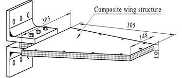
a) Schematic of composite wing structure
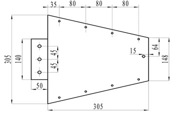
b) Locations of excitation pole and acceleration sensors
c) Photograph of composite specimen
The composite wing structure is horizontally installed on the vertical beam by using a couple of L-type fixtures, as shown in Fig. 2. Quartz lamp infrared heating arrays are installed 60 mm away from the upper and lower surfaces of the composite wing structure to apply radiation heating to the upper and lower surfaces of the wing. In the test process, the time-varying, high-temperature thermal environments are generated and controlled by the transient aerodynamic heating simulation test system.
The exciter is installed underneath the end of the shorter edge of the lower surface of the wing structure, which is connected to the wing structure by a high-temperature metal pole passing through the quartz lamp infrared heating arrays. During the test, the excitation force from the exciter is exerted through the metal pole to excite the wing cantilever structure from the outside of the high-temperature field. In this test, the maximum temperature is up to 1100°C and the test lasts for 1800 s in that high temperature. To avoid substantial strength reduction of the metal pole in high temperature, a water-cooled configuration is designed in the center part of the metal pole to lower the temperature of the pole by water. In order to shield the thermal environment, high-temperature, lightweight ceramic fiber insulation boards that can withstand 1500°C are installed outside of the quartz lamp infrared heating arrays to protect the exciter, sensors and power supply circuits.
Fig. 2Schematic diagram of thermal vibration test setup for wing structure
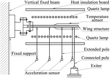
In this test, it is demanded to acquire the vibration signals of the composite wing structure in extreme thermal environments up to 1100°C, so an extension configuration consisting of a high-temperature ceramic hollow pole and specialized connection fixture is designed to transmit the high-temperature vibration signals of the wing. The ceramic pole is made of corundum with a diameter of 4 mm, which can maintain stability at 1,550°C. In order to obtain the modal information of the composite wing structure, eight points in the four cross sections of the wing structure are designed to install vibration signal extension devices. The extended pole is fixed on the wing structure at one end and connected to an acceleration sensor at the other end, which is outside the heating insulation board to collect the vibration signals in the non-high temperature field. Because the acceleration sensors are outside the high-temperature field, ordinary acceleration sensors are used to measure the vibration signals that are difficult to obtain in high temperatures.
2.2. Thermal-vibration joint test system
Fig. 3 shows the structure diagram of the thermal-vibration joint testing system, which consists of an aerodynamic heating simulation control system and a vibration excitation testing system.
Fig. 3Schematic diagram of thermal-vibration joint test system
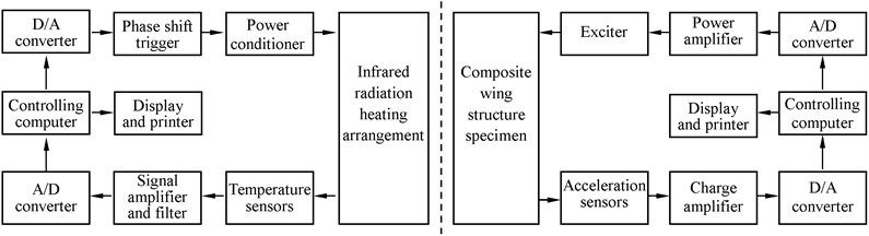
2.2.1. Aerodynamic thermal test analog control system
An aerodynamic heating simulation control system is an independent computer digital closed-loop test and control system composed of infrared heating arrangements, a temperature sensor, signal amplifier and filter, A/D converter, controlling computer, D/A converter, phase trigger and power conditioner, as shown in the left half of Fig. 3. The test system can carry out rapid and accurate non-linear dynamic control on the pre-set aerodynamic heating process according to the transient continuous changes of the heat flux or temperature; and the dynamic tracking error can be controlled within 1 % [16]. The test temperature of the quartz infrared radiation device can reach 1500°C, which is close to the softening temperature of the quartz glass. The thermal control system can also carry out an accurate, dynamic simulation on the non-linear time-varying thermal environment with a heating rate up to 210°C/s or a maximum heat flux up to 1.5 MW/m2 [17]. The system has been applied in practical researches on the thermal environment simulation test for high-speed flight vehicles [18-20].
2.2.2. Vibration excitation testing system
As shown in the right half of Fig. 3, the vibration excitation testing system is composed of acceleration sensors, a charge amplifier, A/D converter, controlling computer, D/A converter, power amplifier and an exciter. When the system works, the controlling computer will calculate the excitation waveform, which will be converted into an analog control voltage signal through the D/A converter. This waveform is used to drive the exciter after being amplified by the power amplifier to make the specimen vibrate according to the required excitation conditions. The vibration signals acquired by the acceleration sensors are amplified and converted by the charge amplifier and D/A converter and are then saved and handled by the controlling computer.
2.3. Thermal environment, excitation signal and modal frequency analysis
The pre-set thermal environments for the composite wing structure are seven different temperature conditions in this paper. The highest temperature of the thermal environments is 1100°C, and the other six temperatures are 200°C, 400°C, 600°C, 900°C and 1000°C, respectively. During the thermal-vibration test, both the upper and lower surfaces of the specimen will be simultaneously heated from room temperature to the target set value within 220 s. Because the test is aimed at stimulating the long-time process of the thermal environments for long-range high-speed flight vehicles, after reaching the pre-set temperature, the thermostatic process of the wing structure will be held for 1580 s to observe and analyze the dynamic characteristics of the wing structure in the long-duration heating environment.
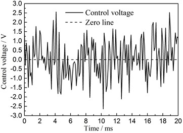
During the heating process, the exciter will send random signals, which are generated by the signal generator and amplified by the power amplifier, to continuously excite the wing structure at the free end, and the vibration response variation versus time and temperature will be measured and recorded by the acceleration sensors. Fig. 4 presents the wave shape of part of the random signals.
Fig. 4Vibration excitation waveshape
From these measurements, the frequency response function of each measuring point on the wing structure specimen corresponding to time and temperatures will be obtained through a time-frequency joint analysis [21], and the regularity of the frequency corresponding to the natural vibration of the study object changing with the temperature will be obtained from this function. The theory is discussed further in the following paragraphs.
The following short-time Fourier transform (STFT) is implemented for the excitation signal of the exciter:
where and represent the th and th discrete values; is the discrete sequence of vibration excitation signals; is the time window function; is the angular frequency.
The following short-time Fourier transform (STFT) is implemented for the acceleration response signal :
where is the discrete sequence of the acceleration signals; and are the vibration excitation signals and acceleration signals that are obtained by the short-time Fourier transform, and the structure transfer function will be obtained by using and as follows:
Modal parameter identification and data processing for are performed to obtain the change regularity of the natural frequency of the test object over time.
3. Experimental results and analysis
Fig. 5 shows the pre-set temperature curves and control temperature curves on the upper and lower surfaces of the composite wing structure in seven different thermal environments with a temperature range of 200°C to 1100°C. The test results shown in Fig. 5 indicate that the “pre-set temperature curve” and “control temperature curve” on both the upper and lower surfaces overlap with each other in the high-temperature vibration test. These two curves show a high consistency with each other in the rising and turning regions of the temperature curve.
Table 1Pre-set and control temperature data on upper and lower surfaces of composite wing structure (1100°C)
Time / s | 50 | 100 | 200 | 300 | 600 | 900 | 1200 | 1500 | 1800 |
Pre-set temperature / °C | 303.9 | 558.8 | 1094.1 | 1100.0 | 1100.0 | 1100.0 | 1100.0 | 1100.0 | 1100.0 |
Control temperature on upper surface / °C | 303.5 | 558.7 | 1094.6 | 1100.8 | 1100.6 | 1100.7 | 1100.6 | 1100.9 | 1100.8 |
Relative error / % | –0.13 | -0.02 | 0.05 | 0.07 | 0.05 | 0.06 | 0.05 | 0.08 | 0.07 |
Control temperature on lower surface / °C | 303.3 | 559.7 | 1093.2 | 1100.9 | 1100.7 | 1101.3 | 1100.7 | 1100.8 | 1100.9 |
Relative error / % | –0.20 | 0.16 | -0.08 | 0.08 | 0.06 | 0.12 | 0.06 | 0.07 | 0.08 |
Table 1 gives the pre-set and control temperature data on the upper and lower surfaces of the composite wing structure. The test results provided in Table 1 show that the tracking error of the upper and lower surfaces of the composite wing structure was less than 0.3 %, suggesting that the thermal test system can implement rapid and accurate dynamic tracking of the pre-set thermal conditions and generate simulation environments coinciding with the preset temperatures.
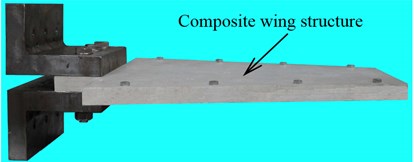
Fig. 6 is a photograph of the thermal-vibration test for the high-temperature-resistant composite wing structure that is simultaneously subjected to the thermal load and excitation.
Fig. 5Pre-set and control temperature curves on upper and lower surfaces of wing structure
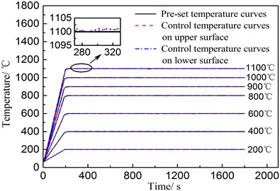
Fig. 6Photograph of thermal-vibration joint test for composite wing structure

Fig. 7Natural frequency curves of composite wing structure in various temperatures
a) First order
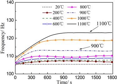
b) Second order
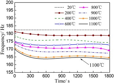
c) Third order
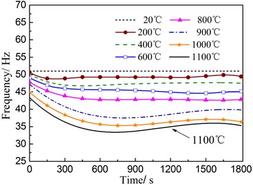
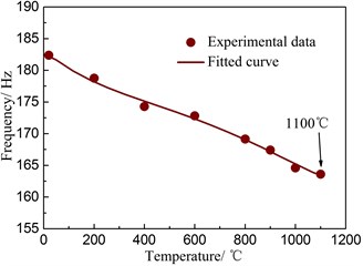
Fig. 7 presents the first-order, second-order and third-order natural frequency curves, which are obtained in the thermal-vibration test, for the composite wing structure in various temperatures ranging from 20°C to 1100°C. Fig. 7(a) and Fig. 7(c) indicate that the first- and third-order frequencies decrease when the temperature of the composite wing structure rises. The higher the heating rate, the faster the changes in the natural frequency and the greater the amplitude of the decrease. The reason resulting in the phenomenon mentioned above is that the elastic properties and the structural stiffness of composite wing structure have changed in high-temperature environments. When the temperatures on the surfaces of the composite wing become steady, the changes in the natural frequencies of each order tend to slow down and gradually reach a relatively stable state. Fig. 7(b) shows that the second-order frequency increases during the temperature rising segments and the second-order natural frequency increases as the temperature increases. When the temperature is constant, the second-order frequency gradually reaches a relatively stable state. It can also be seen in Fig. 7(b) that the amplitude of change of the second-order frequency is comparatively small when the thermal environment temperature is lower than 800°C. Nevertheless, the second-order frequency change is relatively obvious when the temperature of the composite wing structure is beyond 800°C. The test results provide an experimental basis for analyzing the dynamic properties of the SiO2-fiber-reinforced-SiO2 composite wing structure in high-temperature environments.
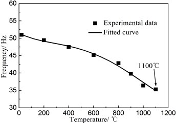
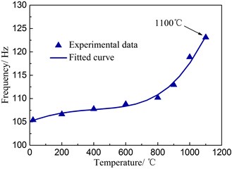
Table 2Test results of natural frequencies at various temperatures (1800 s)
First order / Hz | Second order / Hz | Third order / Hz | |
20°C | 51.0 | 105.4 | 182.4 |
200°C | 49.4 | 106.7 | 178.8 |
400°C | 47.5 | 107.8 | 174.3 |
600°C | 45.2 | 108.8 | 172.8 |
800°C | 42.8 | 110.2 | 169.2 |
900°C | 39.8 | 112.9 | 167.4 |
1000°C | 36.4 | 118.9 | 164.6 |
1100°C | 35.3 | 123.1 | 163.5 |
Fig. 8Frequency variation of composite wing structure at various temperatures (at 1800 s)
a) First order
b) Second order
c) Third order
Table 2 gives the experimental data of the first three-order frequencies for the composite wing structure at 1800 s. Fig. 8 plots the relation curves of the frequencies versus temperatures. Table 2 and Fig. 8 indicate that at 1800 s the first-order and third-order frequencies decrease by 15.7 Hz and 18.9 Hz, respectively, at 1100°C compared with those at room temperature, while the second-order frequency increases by 17.7 Hz. The phenomenon that some order frequencies of the thin shell-like structure that is liable to buckle increase as the temperature increases was observed in previous research [22-23]. This phenomenon is related to the change in the elastic properties of materials, the value and direction of structural thermal stress and the boundary conditions of the structure.
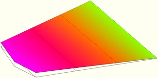
Fig. 9 presents the experimental results for the first three-order modal shapes of the wing structure under 1100°C through comprehensive analysis of the vibration signals obtained by the eight acceleration sensors distributed on the four sections of the wing. As shown in Fig. 9, the first-order and third-order modal shapes are bending mode, while the second-order modal shape is torsional mode. The test results for the modal shape and the change regulation between the frequencies and temperatures can provide an important experimental basis for the analysis of the dynamic characteristics of the composite wing structure in thermal-vibration joint environments.
Fig. 9First three mode shapes of composite wing structure
a) First-order mode shape

b) Second-order mode shape

c) Third-order mode shape
In order to study the impacts of installing the extended poles on the natural frequencies of the composite wing structure, the first-three natural frequency measurements with and without extended poles were performed at room temperature, respectively, and the measured natural frequencies were compared. Table 3 gives the experimental results of natural frequency of composite wing structure with and without poles at room temperature.
Table 3First, second, third order modal frequencies of composite wing structure with/without extended poles at room temperature
First order / Hz | Second order / Hz | Third order / Hz | |
Without extended poles | 54.2 | 108.4 | 190.2 |
With extended poles | 51.0 | 105.4 | 182.4 |
Relative error | –5.9 % | –2.8 % | –4.1 % |
The data in Table 3 shows that due to the impact of the additional mass, the natural frequencies measured with installed extended poles was slightly lower than those measured by the acceleration sensor installed directly on the wing. The first-order, second-order, and third-order frequencies were 5.9 %, 2.8 %, and 4.1 % lower, respectively. All of these differences were less than 6 %, which was not significantly and was generally reasonable in the engineering application. Also, the change trend and quantity date of the above two methods can be used as a reference for analyzing and correcting the experimental data.
4. Conclusions
1) A transient aerodynamic heating simulation system and vibration excitation setup were combined to establish a thermal-vibration joint test system that is able to perform experimental research on the thermal modal of a high-temperature-resistant composite wing structure subjected to high temperatures up to 1100°C for hypersonic flight vehicles.
2) A ceramic extension configuration withstanding high temperature is designed to transfer vibration signals from the composite wing structure to a non-high temperature zone. By using ordinary acceleration sensors, the vibration signals are acquired and the modal shapes of the composite wing structure in extremely high temperature environments up to 1100°C are identified.
3) The key dynamic characteristic parameters (e.g. the natural frequency and mode shape) of the composite wing structure in high-temperature environments up to 1100°C obtained by using a thermal-vibration joint test system can provide an important basis for the dynamic performance analysis and safety design of a composite wing structure under high-temperature thermal-vibration conditions.
References
-
Tang J. Current status and trends of advanced composites in aerospace. Spacecraft Environment Engineering, Vol. 30, Issue 4, 2013, p. 352-359.
-
Du S. Advanced composite materials and aerospace engineering. Acta Materiae Compositae Sinica, Vol. 24, Issue 1, 2007, p. 1-12.
-
Lee I., Lee D. M., Oh L. K. Supersonic flutter analysis of stiffened laminated plates subjected to thermal load. Journal of Sound and Vibration, Vol. 234, 1999, p 49-67.
-
Earl A. T. Thermal Structures for Aerospace Applications. AIAA Press, Reston, 1996.
-
Jeyaraj P., Ganesan N., Chandramouli P. Vibration and acoustic response of a composite plate with inherent material damping in a thermal environment. Journal of Sound and Vibration, Vol. 320, Issue 1-2, p. 322-338.
-
Xia W., Yang Z. Vibration analysis to composite panels in thermal environment. Chinese Journal of Applied Mechanics, Vol. 22, Issue 3, 2005, p. 359-364.
-
Brown A. M. Temperature-dependent modal test analysis correlation of X-34 FASTRAC composite rocket nozzle. Journal of Propulsion and Power, Vol. 18, Issue 2, 2002, p. 284-288.
-
Yiming F., Yang C., Jun Z. Analysis of nonlinear dynamic response for delaminated fiber-metal laminated beam under unsteady temperature field. Journal of Sound and Vibration, Vol. 333, Issue 22, 2014, p. 5803-5816.
-
Yang Z., Xia W., Zhang R. Thermal flutter characteristics of laminated composite panels. Shock and Vibration, Vol. 29, Issue 9, 2010, p. 18-22.
-
Haider N. A., Ali H. N. Nonlinear interactions in the responses of heated annular plates. 45th Structures, Structural Dynamics and Materials Conference, Palm Springs, California, 2004.
-
Malekzadeh P., Fiouz A. R., Sobhrouyan M. Three-dimensional free vibration of functionally graded truncated conical shells subjected to thermal environment. International Journal of Pressure Vessels and Piping, Vol. 89, 2012, p. 210-221.
-
Natalie D. S. High-temperature modal survey of a hot-structure control surface. 27th International Congress of the Aeronautical Sciences, Vol. 3, 2010, p. 2091-2110.
-
Jeon B. H., Kang H. W., Lee Y. S. Free vibration characteristics of rectangular plate under rapid thermal loading. The 9th International Congress on Thermal Stresses, Budapest, Hungary, 2011.
-
Wang Y. Technology research about vibration test under high temperature. Harbin Institute of Technology, 2012.
-
Yu P., Zhang T., Wang X. Flexural property testing for 2.5D SiO2 Fiber-reinforced-SiO2 Composite. Aerospace Materials and Technology, Vol. 5, 2005, p. 58-61.
-
Wu D., Wu S., Wang Y., Gao Z., Yang J. High-speed and accurate non-linear calibration of temperature sensors for transient aerodynamic heating experiments. Transactions of the Institute of Measurement and Control, Vol. 36, Issue 6, 2014, p. 845-852.
-
Wu D., Pan B., Gao Z., Mu M, Zhu L., Wang Y. On the experimental simulation of ultra-high temperature, high heat flux and nonlinear aerodynamic heating environment and thermo-mechanical testing technique. Journal of Experimental Mechanics, Vol. 27, Issue 3, 2012, p. 255-271.
-
Wu D., Zheng L., Pan B., Sun B., Mu M. Experimental study and numerical simulation on heat-shielding properties of superalloy honeycomb panel for non-linear high temperature environment. Chinese Journal of Theoretical and Applied Mechanics, Vol. 44, Issue 2, 2012, p. 297-307.
-
Zheng L., Wu D., Pan B., Wang Y., Sun B. Experimental investigation and numerical simulation of heat-transfer properties of metallic honeycomb core structure up to 900°C. Applied Thermal Engineering, Vol. 60, 2013, p. 379-386.
-
Wu D., Wang Y., Pan B., Mu M., Zhu L. Experimental research on the ultimate strength of hard aluminum alloy 2017 subjected to short-time radioactive heating. Materials and Design, Vol. 40, 2012, p. 502-509.
-
CohenL. Time-Frequency Analysis: Theory and Applications. Xi’an Jiaotong University Press, Xi’an, 1998.
-
Wu D., Zhao S., Pan B., Wang Y., Mu M., Wu S. Research on thermal-vibration joint test for wing structure of high-speed cruise missile. Acta Aeronautica et Astronautica Sinica, Vol. 33, Issue 9, 2012, p. 1633-1642.
-
Wu Z., Cheng H., Zhang W., Li H., Kong F. Effects of thermal environment on dynamic properties of aerospace vehicle panel structure. Acta Aeronautica et Astronautica Sinica, Vol. 34, Issue 2, 2013, p. 334-342.
About this article

This work was supported by the National Natural Science Foundation of China (No. 11427802 and No. 11172026) and the Specialized Research Fund for the Doctoral Program of Higher Education (No. 20131102110014).
