Abstract
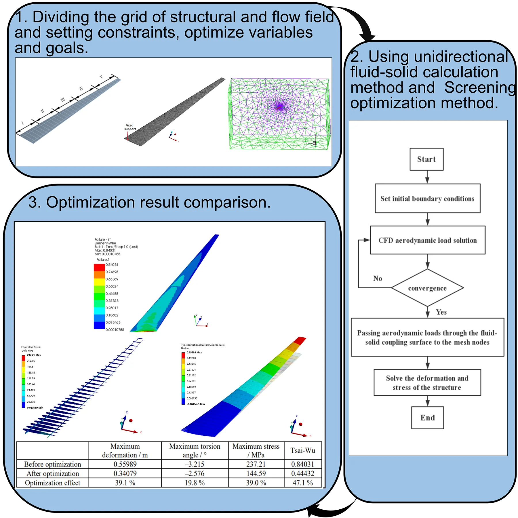
In order to reduce the weight and improve aerodynamic characteristics, the new aircraft generally adopts lightweight composite materials and high-aspect-ratio layout. Such the structural layout aircraft will produce large nonlinear aeroelastic deformation under the action of aerodynamic loads. Due to the anisotropy of the composite, the composite ply angle of wing skin has a great influence on the elastic deformation of the high-aspect-ratio wing. In order to study the influence of the ply angle on the nonlinear static aeroelastic wing deformation, based on CFD/CSD unidirectional fluid-solid coupling, the structural deformation and stress of high-aspect-ratio composite wing were numerically solved. The wing deformation along the lift direction was taken as the optimization target. The structure strength was taken as the constraint. The ply angle for the composite skin of the high-aspect-ratio composite wing was optimized by the Screening method. The optimization results show the nonlinear static aeroelastic deformation of the wing in the lift direction is reduced by 39.1 %. The maximum stress of the wing beam and rib is reduced by 39.0 %. The maximum Tsai-Wu failure factor of the wing skin is reduced by 47.1 %.
Highlights
- After optimized,the torsional deformation of the high-aspect-ratio wing is significantly reduced, that improves the aerodynamic characteristics of the high-aspect-ratio wing
- The nonlinear static aeroelastic deformation and negative torsion angle of the asymmetrically ply wing are significantly smaller than the symmetrically ply wing
- In the structural design, the asymmetric ply method shall be adopted
1. Introduction
Composite materials have the characteristics of small specific gravity, large specific modulus and specific strength, and good designability, which have been widely used in unmanned aerial vehicle (UAV) structures. Appropriate addition of composite materials in the UAV structure can both achieve the effect of weight reduction, and improve other performance parameters of the UAV structure through optimization design [1]. Due to the anisotropy of composite plies, composite structure can exhibit different mechanical properties by varying the ply number, thickness, and angle. Therefore, the optimization design of composite wing structure has always been a hot issue for scholars at home and abroad [2].
Domestic and foreign scholars have done a lot of research on the optimization of composite wing plies. Yi et al. [3] implanted the semi-analytical sensitivity analysis technique into ANSYS to achieve an alternative design for the composite wing, reducing the total mass of the wing structure by approximately 24 %. Dáugosz et al. [4] optimized the design of the composite UAV structure for the purpose of improving strength and stiffness and reducing the weight of the structure. Wan et al. [5] proposed a genetic/sensitivity hybrid optimization algorithm for aeroelastic optimization design of high-aspect-ratio composite wings. Under the premise of satisfying the constraints of strength, displacement, divergence speed and flutter speed, the ply thickness of each component of the wing was taken as the design variable, and the weight of the structure was minimized. For a high-aspect-ratio composite wing, Shi et al. [6] used the genetic algorithm to optimize the structural dimensions and composite plies to reduce the weight of the wing structure. Shi et al. [7] took a long-haul UAV wing as the research object, with the wing bending deformation as the constraint, and the minimum wing quality as the design goal. The shell ply thickness and the beam section size in the wing structure were respectively optimized. The results show that the wing weight loss is 18.52 % after structural optimization. Basri et al. [8] studied the effect of the ply angle on composite plies and evaluated the performance of the NACA4415 drone wing. Liu et al. [9] established a two-level wing layout optimization method. In the first level, aiming at the wing stiffness, the response surface method is used to optimize the spar position. In the second level, the wing structure quality is taken as the objective function, and the genetic algorithm is used to optimize the ply parameters of the wing components. Under the premise of meeting the design requirements of strength and stiffness performance, about 25 % weight of wing structure is reduced. Wan et al. [10] performed an aeroelastic analysis on the high-aspect-ratio composite wings with unbalance plies in upside and downside skins. The unbalance level of the skin plies has little effects on the natural frequencies and flutter speed, but great effects on the divergence speed and static aeroelastic characteristics of the wings. Zhou et al. [11] carried out a comprehensive aeroelastic optimization design of high-aspect-ratio composite wing. The composite ply thickness is taken as the design variable, and various aeroelastic constraints and strength/strain constraints are used as its constraints. The structure is optimized. The influence of the skin ply parameters is analyzed from the aspects of ply proportion and ply unbalance. Lu et al. [12] optimized the aerodynamic elastic of the wing composite skin with the minimum structural weight as the optimization goal. In optimization, the ply thickness of the wing skin plies was adopted as design variables, and strength/strain constraints are used as constraints.
Through the above research work has been done at home and abroad, it is found that the optimization design of composite wing was mainly focused on the optimization of the weight and the aerodynamic of composite wing by using the ply thickness as the design variable. There are few studies on the effects of ply angle on the nonlinear static aeroelasticity of high-aspect-ratio composite wing. Based on the CFD/CSD unidirectional fluid-solid coupling method, the aerodynamic load was solved by the Navier-Stokes (N-S) governing equations, and coupled to solve the nonlinear structural motion equation. The deformation and stress of the high-aspect-ratio composite wing was obtained. The wing deformation along the lift direction was taken as the optimization target. The structure strength was taken as the constraint. The ply angle of the composite wing skin was optimized, and the optimization results were analyzed.
2. Materials and method
2.1. Computation methodology
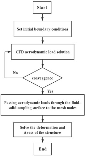
The unidirectional fluid-solid coupling calculation method was adopted, and the N-S equation was used as the governing equation to calculate the flow field to obtain the aerodynamic load. After the flow field calculation was converged, the aerodynamic load was loaded onto the structural grid node through the numerical interpolation technique. The finite element method was used to solve the wing structure, and the deformation and stress of the wing under the aerodynamic load were obtained. The coupling calculation process is shown in Fig. 1.
2.1.1. Flow field solution technique
During the static aeroelastic solution process, the deformation speed is slow. The influence of acceleration and deformation speed on aerodynamics can be ignored. The integral form of the N-S equation has been used as the governing equation, and the expression in the Cartesian coordinate system is [13]:
where, is the flow field conservation variable term. and are the flux term and the dissipation flux term, respectively. is the limit of the control volume. is the control unit. and are the volume element and the area element, respectively. After introducing the Stokes hypothesis and the gas state equation , the system of equations becomes closed. The Spalart-Allmaras turbulence model [14] was selected to simulate the flow field. The convection term was discretized using the second-order accuracy Roe-FDS [15], and the viscous terms were discretized by central differential interpolation [16].
Fig. 1Unidirectional fluid-solid coupling calculation process
For the steady flow, the discrete form of the governing Eq. (1) is:
where, is the residual value of the semi-discrete equation. and are the non-viscous flux term and the viscous flux term, respectively. The Eq. (2) can be solved by the LU-SGS implicit time-discrete method with first-order precision [17].
2.1.2. Structural solution technique
The equation of motion balance of a structure under aerodynamic loads is:
where, , and are the mass matrix, the damping matrix and the stiffness matrix, respectively. and are the external load vector and the displacement vector, respectively.
Since the static aeroelastic structure is slowly deformed, the influence of deformation speed, acceleration and time on the aerodynamic force can be neglected, so that Eq. (3) can be simplified as:
The steady aerodynamic force is calculated according to the Eq. (1), and the corresponding structural deformation can be calculated by solving the Eq. (4).
2.2. Mathematical model for optimization of ply angle
The ply angle was taken as the design variable. The wing beam and rib stress satisfied the strength condition, which was taken as the constraint. The composite skin of the wing satisfies the Tsai-Wu failure condition was taken as the constraint similarly. The maximum deformation of the wing is less than 15 % of the half-span, which was taken as the optimization objective. The ply angle for the composite skin of the high-aspect-ratio composite wing was optimized by the Screening method [18]. Its mathematical expression is as shown in Eq. (5):
where , and is the maximum deformation. is the maximum wing beam and rib stress. - is the maximum Tsai-Wu failure factor of the composite wing skin.
2.3. Computation methodology verification
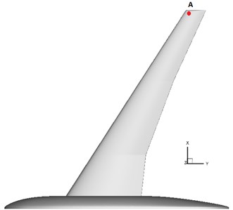
Taking the HIRENASD wing model as the research object, the accuracy of the proposed static aeroelastic calculation method was verified. The geometry of the HIRENASD wing model [19] is shown in Fig. 2. The reference area is 0.3926 m2and the reference length is 0.3445 m [20]. Fig. 3 is the position of point to compare with experimental data.
Fig. 2The geometry of HIRENASD wing model
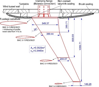
Fig. 3The position of point A compared with the experimental data
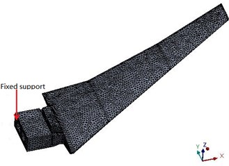
In the static aeroelastic calculation, the flow field adopted a hybrid mesh, and the mesh near the object surface was refined. In order to make more realistic fluid simulation, the inflation layer was inserted around the wing. A five-layer hexahedron or wedge mesh was generated around the wing, and then the rest tetrahedral unstructured meshes were made. The number of generated nodes was 793809, and the number of grids was 3308576. The grid near the object surface is shown in Fig. 4. The plane of the fuselage root was set to a symmetrical boundary condition, the wing and the fuselage were set to the object boundary condition, and the other ones were set to the pressure far away from the field boundary condition. The HIRENASD wing finite element structure model was meshed by unstructural tetrahedrons, with a total of 90963 nodes and 51747 grid elements. The finite element model of the wing was constrained by the fixed support of the wing root, as shown in Fig. 5.
Fig. 4Grid near the surface of the HIRENASD model
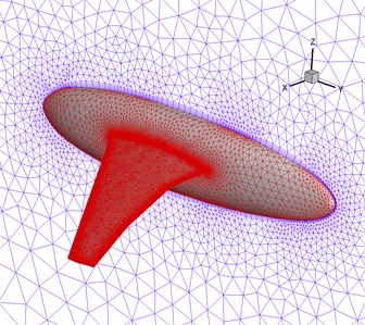
Fig. 5HIRENASD wing structure finite element mesh
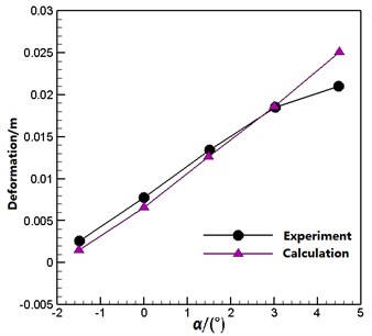
The calculated Mach number was 0.8, and the Reynolds number was 7×10⁶. The angle of attack were –1.5°, 0°, 1.5°, 3° and 4.5°, respectively. Fig. 6 shows a comparison of the deformation of the point of the wing in the direction at different angles of attack between calculation and experiment [21]. It can be seen that the calculated values agree well with the experimental values. It is shown that the static aeroelasticity numerical simulation method can be used for the analysis of static aeroelastic problems.
Fig. 6Deformation of the point A of the HIRENASD wing in the Z direction at different angles of attack
2.4. Composite wing ply setting and meshing
The high-aspect-ratio wing was adopted for analysis. The wing airfoil is the ONERA D section. The wing is a swept wing with zero upper and reverse angles. The geometric model and dimensions of the wing are shown in Fig. 7. The reference area is 3.675 m2, and the reference length is 0.6125 m. The material of the wing beam and rib is titanium alloy. The yield strength is 930 MPa, and the safety factor is 1.5. The front beam has a thickness of 30 mm. The back beam has a thickness of 25 mm. The rib has a thickness of 20 mm. The material of the wing skin is carbon fiber composite, and the material properties are shown in Table 1. The area division of the wing skin ply is shown in Fig. 8. The wing skin is symmetrically ply. The number of plies at the wing root is the largest, and the number of plies is gradually reduced along the span, as shown in Table 2.
Fig. 7High-aspect-ratio composite wing model geometry
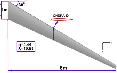
Fig. 8Area division of high-aspect-ratio composite wing skin ply
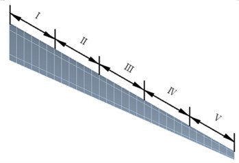
Table 1Carbon fibre composite epoxy carbon UD (230 GPa) prepreg properties
Density [Kg⋅m-3] | Elastic modulus [GPa] | Shear modulus [GPa] | Poisson’s ratio | ||||||
1490 | 121 | 8.6 | 8.6 | 4.7 | 3.1 | 4.7 | 0.27 | 0.4 | 0.27 |
Table 2Settings for wing skin ply
Region | Thickness /mm | Number of plies | Ply setting |
Ⅰ | 22 | 22 | |
Ⅱ | 20 | 20 | |
Ⅲ | 18 | 18 | |
Ⅳ | 14 | 14 | |
Ⅴ | 10 | 10 |
The structure of the wing model mainly includes skins, spars, and ribs, all of which were meshed by shell 181 shell elements. The number of generated nodes was 66504, and the number of grids was 23775. The finite element model of the wing is constrained by a fixed support of the wing root, as shown in Fig. 9.
Fig. 9Finite element model of the high-aspect-ratio composite wing
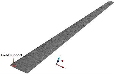
a) Boundary condition setting of finite element model
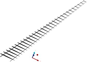
b) Internal structure of finite element model
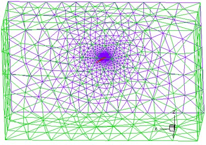
Fig. 10 shows the flow field calculation domain and the local mesh division near the wing. The unstructured tetrahedral mesh was used for mesh division, and the number of grid cells was 2.8×10⁶. The wing root was set as a symmetrical boundary condition, the wing was set to the object boundary condition, and the rest ones were set as the pressure far away from the field boundary condition.
Fig. 10Calculation domain and mesh of flow field
a) Overall computing domain
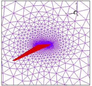
b) Grid near the wall
3. Results
3.1. Analysis of elastic deformation of high-aspect-ratio composite wing before optimization
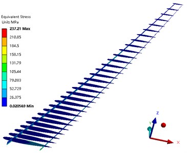
The problem of nonlinear static aeroelastic deformation of the composite wing was solved under the condition that the Mach number was 0.7, the Reynolds number was 9.98×10⁶, and the angle of attack was 4°. Fig. 11 shows the deformation of the composite wing in the lift direction. Fig. 12 depicts the stress distribution of the wing beam and rib. Fig. 13 is the Tsai-Wu failure factor distribution of the wing composite skin. It can be seen from the figure that the maximum wing deformation is 0.55989 m. The maximum torsion angle of the wing is –3.215°. The maximum stress of the wing beam and rib is 237.21 MPa. The maximum Tsai-Wu failure factor of the wing skin is 0.84031. Although the structural strength condition is satisfied, the torsional deformation of the wing in the lift direction is too large, which reduces the aerodynamic characteristics of the high-aspect-ratio wing.
Fig. 11Deformation of the wing along the Z axis
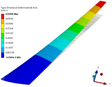
Fig. 12Stress distribution of the wing beam and rib
3.2. Optimization result analysis
In order to find the optimum ply angle, the torsional deformation of the high-aspect-ratio wing was minimized. The ply angle of the wing skin was optimized. In the optimization process, the wing skin was asymmetrically ply. Thus, 16 independent variables were set. The wing deformation along the lift direction was taken as the optimization target. The structure strength was taken as the constraint. The screening method was taken as the optimization method. The total number of samples was defined as 100, and these 100 samples were analyzed. Finally, the three candidate points with the smallest deformation were obtained as shown in Table 3. Under the condition that the structural strength was satisfied, the deformation of the candidate point 1 was the smallest, so the candidate point 1 was selected as the final optimization result. The final results of the ply angle optimization of the wing skin are shown in Table 4.
Fig. 13Tsai-Wu failure factor distribution of the wing composite skin
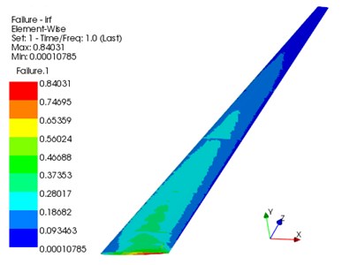
Table 3Optimization candidate list
Candidate point | 1 | 2 | 3 |
45 | 90 | 45 | |
–45 | –45 | –45 | |
90 | 45 | 45 | |
–45 | –45 | 90 | |
45 | –45 | 45 | |
45 | –45 | 45 | |
45 | 90 | –45 | |
–45 | 90 | 90 | |
90 | 0 | 90 | |
90 | 45 | 90 | |
–45 | –45 | –45 | |
90 | –45 | 90 | |
0 | 90 | 0 | |
–45 | 90 | –45 | |
–45 | 90 | –45 | |
90 | 45 | 90 | |
Deformation/m | 0.34079 | 0.34207 | 0.34777 |
Stress/MPa | 144.59 | 141.45 | 147.37 |
Tsai-Wu | 0.44432 | 0.43862 | 0.45205 |
Table 4Optimized settings for wing skin ply
Region | Ply setting |
Ⅰ | |
Ⅱ | |
Ⅲ | |
Ⅳ | |
Ⅴ |
Fig. 14 shows the wing deformation along the lift direction after optimization. Fig. 15 shows the stress distribution of the wing beam and rib after the optimization. Fig. 16 shows the Tsai-Wu failure factor distribution of the wing composite after the optimization. It can be seen from the figure that the maximum wing deformation is 0.34079 m. The maximum torsion angle of the wing is –2.576°. The maximum stress of the wing beam and rib is 144.59 MPa. The maximum Tsai-Wu failure factor of the wing skin is 0.44432. It can be seen that the optimized wing still meets the strength conditions.
Fig. 14Deformation of the wing along the Z axis
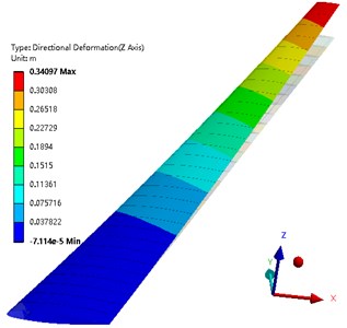
Fig. 15Stress distribution of the wing spar and rib
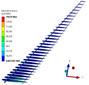
Fig. 16Tsai-Wu failure factor distribution of wing composite skin
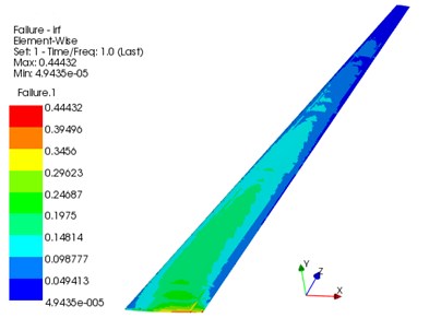
Table 5 shows the comparison of optimization results. It can be seen from the table that the deformation in the lift direction and torsion angle of the wing are reduced: the maximum deformation is reduced by 39.1 %, and the maximum torsion angle is reduced by 19.8 %. The maximum stress of the wing beam and rib is reduced by 39.0 %, and the maximum Tsai-Wu failure factor of the wing skin is reduced by 47.1 %. This indicates that the torsional deformation of the wing is significantly reduced under the constraint of strength.
Table 5Optimization result comparison
Maximum deformation / m | Maximum torsion angle / ° | Maximum stress / MPa | Tsai-Wu | |
Before optimization | 0.55989 | –3.215 | 237.21 | 0.84031 |
After optimization | 0.34079 | –2.576 | 144.59 | 0.44432 |
Optimization effect | 39.1 % | 19.8 % | 39.0 % | 47.1 % |
4. Conclusions
For ensuring the structural strength, and for reducing the influence of the ply angle on the nonlinear static aeroelasticity of the aircraft, the composite skin ply angle of the high-aspect-ratio composite wing was optimized by the Screening method. The conclusions of the research results are as follows.
After the ply angle of the wing skin was optimized, the wing deformation along the lift direction is reduced by 39.1 %. The torsion angle of the wing is reduced by 19.8 %. The torsional deformation of the high-aspect-ratio wing is significantly reduced, that improves the aerodynamic characteristics of the high-aspect-ratio wing.
The nonlinear static aeroelastic deformation and negative torsion angle of the asymmetrically ply wing are significantly smaller than the symmetrically ply wing. The results show that in the structural design, the asymmetric ply method shall be adopted.
References
-
Feng Yan., Zheng Xitao., Wu Shuyi., et al. Layup optimization design and analysis of super lightweight composite wing. Acta Aeronautica Et Astronautica Sinica, Vol. 36, Issue 6, 2015, p. 1858-1866.
-
Lin Fapeng, Zhuo Aibao, Yu Cungui An optimum design of ply orientation angle in composite materials director of rocket launcher. Materials Review, Vol. 25, Issue 3, 2011, p. 135-138.
-
Yi L., Hong H. Q., Li Y. L. Optional design research of a composite wing based on sensitivity analysis. Advanced Materials Research, Vol. 421, 2011, p. 687-692.
-
Dáugosz A., Klimek W. The optimal design of UAV wing structure. AIP Conference Proceedings, Vol. 1922, 2018, p. 120009.
-
Wan Zhiqiang, Yang Chao Aeroelastic optimization of a high-aspect-ratio composite wing. Acta Materiae Compositae Sinica, Vol. 22, Issue 3, 2018, p. 145-149.
-
Shi Xudong, Chen Liang, Zhang Bihui, et al. Structural optimization design of high aspect ratio composite wing based on genetic algorithm. Advances in Aeronautical Science and Engineering, Vol. 6, Issue 1, 2015, p. 110-115.
-
Shi Jituo, Wang Hongwei, Hua Xin Structure optimization design of high aspect ratio composite wing. Journal of Ordnance Equipment Engineering, Vol. 39, Issue 11, 2018, p. 179-183.
-
Basri E. I., Sultan M. T. H., Faizal M., et al. Performance analysis of composite ply orientation in aeronautical application of unmanned aerial vehicle (UAV) NACA4415 wing. Journal of Materials Research and Technology, Vol. 8, Issue 5, 2019, p. 3822-3834.
-
Liu Bo, Lu Zhenyu, Yuan Dongming, et al. Layout optimization of composite uav wing structure based on two-level optimization method. Fiber Reinforced Plastics/Composites, Vol. 4, 2016, p. 31-35.
-
Wan Zhiqiang, Shao Ke, Yang Chao, et al. Aeroelastic analysis of composite wings with unbalance laminates. Acta Materiae Composite Sinica, Vol. 25, Issue 1, 2008, p. 196-199.
-
Zhou Lei, Wan Zhiqiang, Yang Chao Effect of laminate parameters of composite skin on aeroelastic optimization of high aspect ratio composite wing, Acta Materiae Compositae Sinica, Vol. 30, Issue 5, 2013, p. 195-200.
-
Liang Lu, Wan Zhiqiang, Yang Chao Aeroelastic optimization on composite skins of large aircraft wings. Science China Technological Sciences, Vol. 55, Issue 4, 2012, p. 1078-1085.
-
Zhou Qiang, Li Dongfeng, Chen Gang, et al. General static aeroelasticity analysis method based on CFD/CSM coupling. Journal of Aerospace Power, Vol. 33, Issue 2, 2018, p. 355-363.
-
Orang A. A. Genuinely characteristic-based scheme for the incompressible turbulent flows. Computers and Fluids, Vol. 103, 2014, p. 175-185.
-
Mi Baigang, Zhan Hao, Zhu Jun Calculation of dynamic derivatives for aircraft based on CFD technique. Acta Aerodynamica Sinica, Vol. 32, Issue 6, 2014, p. 834-839.
-
Jameson A. Numerical simulation of the Euler equations by finite volume method using Runge-Kutta time stepping schemes. AIAA Paper 1981-1259, 1981.
-
Parsani M., Abeele K. V. D., Lacor C., et al. Implicit LU-SGS algorithm for high-order methods on unstructured grid with p-multigrid strategy for solving the steady Navier-Stokes equations. Journal of Computational Physics, Vol. 229, Issue 3, 2010, p. 828-850.
-
Pan Lechen Ansys Workbench based optimization analysis of tower crane jib structure. Mechanical Engineering and Automation, Vol. 2, 2015, p. 77-78.
-
Ballmann J., Dafnis A., Korsch H., et al. Experimental analysis of high Reynolds number aero-structural dynamics in ETW. AIAA 2008-841, 2008.
-
Heeg J., Ballmann J., Bhatia K., et al. Plans for an aeroelastic prediction workshop. IFASD 2011-110, 2011.
-
Chwalowski P., Florance J. P., Heeg J., et al. Preliminary computational analysis of the HIRENASD configuration in preparation for the aeroelastic prediction workshop. IFASD 2011-108, 2011.
About this article

This work was supported by the National Natural Science Foundation of China (No. 51605270), the Science Technology Department Key Project of Shaanxi Province (No. 2017ZDXM-GY-138), the Natural Science Research Project of Shaanxi Province (No. 2018JM6084), and Shaanxi Provincial Department of Education Scientific Research Project (19JK0172).
Shuai Lei and Junli Wang conceived and designed the work and wrote the manuscript. Tuolei Li established a three-dimensional model of the wing. Wengsheng Zhang revised and edited the manuscript. Zhigui Ren and Hong Cui helped perform the analysis with discussions.
