Abstract
Abrupt variations of track stiffness in transitions from conventional to slab track, e.g., over bridges and tunnels, usually lead to passenger discomfort, vehicle and track damage and even safety issues. Therefore, to minimize this negative effect, it is very convenient to smooth the stiffness changes in such transitions; and wedges arise as a very effective technique. Although granular wedges are commonly suggested by railroad managers as a solution, this typology presents some disadvantages, e.g., high construction time and costs, that should be addressed. In this paper, a new solution based on prefabricated, reinforced concrete slabs is presented and its dynamical performance is assessed by means of a 3D FEM model. Results indicate that track vibrations both on the rail and over a sleeper are considerably reduced when the new slab-based wedge is considered instead of a traditional granular wedge.
1. Introduction
A severe increase in railway traffic, axle loads and train speeds has been experienced during last decades, together with a strengthen of safety, passenger comfort and track quality requirements, especially in high-speed railways. On the other hand, although the construction of bridges and tunnels along railway tracks is usually necessary, the presence of these structures results in abrupt variations of vertical stiffness between adjacent sections of the track.
According to [1, 2], the most common issues in transition zones (e.g., safety, passenger comfort, and maintenance expense problems) generally arise from differential settlements between adjacent cross-sections of track. Furthermore, such elevation change induces a vertical acceleration of the vehicle mass, which generates an increase in the wheel-rail interaction forces [3]. In this regard [4] reported, for the case of freight trains, vertical dynamic loads two times higher than the value of the static wheel load. Such type of loading favors the enlargement of differential settlements, thus creating a cyclical damage process. Moreover, [5] concluded that maintenance frequency is four to eight times higher over transition zones when compared with a normal section of the track. Therefore, in order to address track integrity issues, many solutions have been proposed to smooth the stiffness transition near structures.
Increasing track stiffness by placing long ties on the ballasted track side is a common solution in the U.S. Nevertheless, experimental results from [6] demonstrated that this solution does not provide a long-term improvement. The use of approaching slabs is another widely-extended alternative, although [7] reported a significant increment in maintenance needs for these particular structures. Further studied solutions include geotechnical improvement (e.g., compaction, stone columns) [6], construction of hot mixed asphalt (HMA) layers [8], placement of additional rails on the ballasted track [9], installation of rail seat pads on open-deck bridges and direct-fixation structures; and use of rubber tie mats [10].
Most European track managers propose the use of granular wedges to mitigate transition problems, as reported in [11]. However, the construction of this type of transition involves high transportation costs and construction periods, problematic quality control and susceptibility to settlement with time.
In this paper, a safe and cost-effective solution to smooth stiffness transitions between ballasted and slab track is presented. The static behavior of a new type of transition wedge made of prefabricated concrete slabs was assessed in [12]. Therefore, the aim of this study is to investigate the dynamic behavior of such new wedge by means of a 3D finite elements model. Furthermore, the performance of this new solution is compared with a classical granular wedge, such as those commonly used in Europe.
2. Description of the prefabricated wedge
Besides providing a gradual stiffness variation to the track, the new transition wedge aims to minimize the risk of differential settlements, as well as to diminish vertical vibrations in both the track and the vehicle, thus reducing potential damage and improving passenger comfort.
According to [11], the design of transition wedges depends on the distance between the top of the structure and the track. In these regard, the new wedge has been designed to be adaptable to every situation. Moreover, the static analysis presented in [12] revealed that the performance of the new solution is better -compared with that of the granular wedge- for larger stiffness differences between the ballasted and the slab track. In other words, the new solution is more convenient for transitions involving abutment structures (e.g., bridges) than buried structures (e.g., tunnels). Consequently, in this paper only bridge-abutment transitions will be analyzed, given that this is the most adverse situation attending to both, track maintenance and passenger comfort.
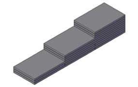
The new solution is composed of prefabricated reinforced concrete slabs (the dimensions adopted for this study are detailed in Fig. 1) stacked one over the other, which conforms the wedge depicted in Fig. 2. It must be pointed out that the solution can be adapted to any particular situation just by modifying the dimensions of the slabs. Further details on the design of the new transition wedge are available in [12].
Fig. 1Prefabricated reinforced concrete slab dimensions
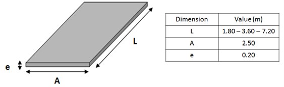
Fig. 2Design of the new transition wedge
3. Description of the model
In order to compare the performance of the new transition wedge to the widely-extended granular solution, a 3D FEM model has been used to reproduce the interaction between soil, track, structure and vehicle in three different scenarios. In this regard, the first scenario does not consider any transition wedge; the second one reproduces a traditional granular wedge; and the third one simulates the slab-based wedge. The numerical model has been developed within ANSYS LS-DYNA software framework, and is divided in two sub-models: a vehicle model and a soil-structure-track model. In this section, the aforementioned sub-models are presented, together with the interaction between them.
The dynamic response of the soil-structure-track sub-model is calculated by relating the internal and external forces of the system. Such relationship can be expressed by means of the equation of motion:
where is the global mass matrix, is the damping matrix; is the stiffness matrix; , , and are the displacement, velocity and acceleration vectors; and is the vector of time-dependent external forces. According to [13], the damping matrix () can be expressed as:
where and are the Rayleigh coefficients and the external forces are given by the vehicle sub-model described below. Hence, displacements, velocities and accelerations can be calculated for each node of the model by solving Eq. (1). The studied frequency range varies between 2 and 100 Hz, which determines the model dimensions as well as the size of the 8-node hexahedral elements, as detailed in [13]. It should be pointed out that the system displacements are limited to the elastic range in the stress-strain diagram, since train loads do not induce large strains in the soil. Therefore, the material behavior is assumed to be linear elastic.
The cross section of the track is that of a typical high-speed railway line, and its main parameters have been determined according to [14]. Hence, the ballast, sub-ballast and formation layer thicknesses are 40 cm, 30 cm and 60 cm, respectively. Furthermore, shoulders in the ballast layer and the embankment are 50 cm long, with a 3H:2V slope and the UIC-60 rails rest on a rail pad which simultaneously lies on concrete sleepers. The mechanical characteristics of the principal track elements are presented in Table 1.
Table 1Material characteristics considered in the model
Material | Young modulus [N/m2] | Poisson ratio [–] |
Rail steel | 2.100×10¹¹ | 0.30 |
Elastic rail pad | 1.234×10⁸ | 0.45 |
Sleeper element 1 | 7.130×10¹⁰ | 0.25 |
Sleeper element 2 | 5.000×10¹⁰ | 0.25 |
Sleeper element 3 | 2.820×10¹⁰ | 0.25 |
Ballast | 1.300×10⁸ | 0.20 |
Sub-ballast | 1.200×10⁸ | 0.30 |
Formation layer | 8.000×10⁷ | 0.40 |
Top embankment material | 6.000×10⁷ | 0.30 |
Core embankment material | 3.000×10⁷ | 0.30 |
Foundation material | 4.500×10⁷ | 0.30 |
Granular material with cement | 1.600×10⁸ | 0.25 |
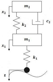
On the other hand, the vehicle sub-model considers a three-mass system accounting for the wheel, a bogie and the car-body masses. The masses are linked with parallel springs and dampers, which aim to reproduce the effect of the primary and secondary suspensions (Fig. 3). The wheel-rail interaction is modelled as a node-to-beam contact and the simulation of sliding and loss of contact is done by means of the Penalty algorithm. Moreover, the contact elements permit an elastic rail-wheel interaction, thus reproducing a Hertzian contact. A full Newton-Raphson method has been employed for the solution of the non-linear equations, while Newmark implicit time integration method has been used to solve those of transient dynamic equilibrium.
Calibration and validation of the numerical model was carried out with data provided by field tests on a real track stretch of the Antequera-Granada high speed line, Spain. For this purpose, a 23 m long granular wedge and a 21.6 m long concrete slab wedge were built on each side of an existing culvert according to [12], and the section was heavily instrumented (e.g., strain gauges, pressure transducers, LVDT transducers). On the other hand, the loading was performed by means of a 26 T, four-axis truck running over the track stretch at 30 km/h and 60 km/h. The measurements (maximum pressure and deformations on the different layers) were compared with those provided by the numerical model (static analysis) in order to obtain the unknown parameters such as the elasticity modulus of the soil. Once calibrated, new registers were compared in order to validate the model.
Fig. 3Simplified scheme of the three-masses system
4. Results
The main problems induced by abrupt changes of track stiffness include safety, passenger comfort, as well as track and vehicle damage. Thus, the new slab-based transition wedge has been compared to the other cases (track without transition wedge and a granular wedge) in terms of: i) dynamic forces on the wheel-rail contact; ii) accelerations on the unsprung masses of the vehicle; and iii) accelerations in two critical points of the track, on a rail and over a sleeper.
4.1. Dynamic forces
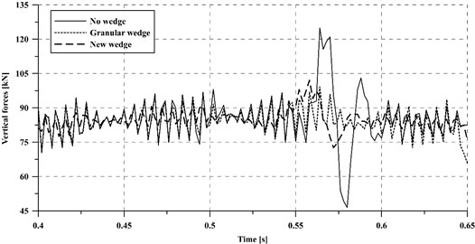
Regarding dynamic forces on the wheel-rail contact, Fig. 4 presents a comparison between the three studied cases. According to the figure, the dynamic forces in the transition section are substantially higher (30 %) when no measure is taken to smooth the stiffness variation, as expected. Moreover, dynamic vertical forces are generally smaller for the new slab-based wedge than for the granular one. This results in an advantage for the new solution, since dynamic forces are the main cause of passenger discomfort, track and vehicle damage and the generation of noise and vibrations.
Fig. 4Comparison of dynamic forces in the rail-wheel contact
4.2. Vibrations at the unsprung masses of the vehicle
In order to evaluate the effect of the transition on the vehicle, the vibrations registered on its unsprung masses have been assessed during the passage of a train through the transition section. Fig. 5 shows a comparison between accelerations on the unsprung masses for the three studied cases. In this regard, transition wedges noticeably favor the decrease of acceleration levels -the peak shown for the case without wedge is clearly reduced (around 75 %) in the other two cases-, which is in agreement with the behavior shown for the dynamic forces. Furthermore, the vibration mitigation capacity of both wedge typologies results similar.
It is well known that, despite following a non-linear behavior, the dynamic forces and the accelerations transmitted to both the vehicle and the track are greater for higher train speeds. Although this trend is supposed to occur in all the studied cases, a certain increase in vehicle speed may not influence each of them to the same extent. In order to assess how vehicle speed influences the vibration attenuation capacity of each case, the acceleration of the vehicle unsprung masses has been calculated for a vehicle speed of 350 km/h (Fig. 6).
In this regard, the case without transition wedge results the most affected by a 40 % increase of vehicle speed from 250 km/h to 350 km/h, presenting a maximum absolute variation of 110 %. On the other hand, the case with a granular wedge results the least affected by an increase of train speed (around 28 % absolute increment).
Although the convenience of using wedges for smoothing track stiffness transitions has been demonstrated, further information is needed to know whether the new solution behaves better than the granular one. In the following, comparisons will only involve the granular and the slab-based wedges.
Fig. 5Accelerations of the vehicle unsprung masses at a 250 km/h train speed
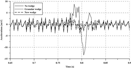
Fig. 6Accelerations of the vehicle unsprung masses at a 350 km/h train speed
4.3. Vibrations in the track
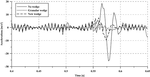
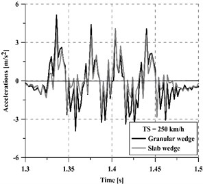
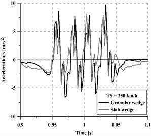
Apart from the dynamic loads applied to the track because of the wheel-rail interaction, the generated vibrations are considered one of the principal causes of track damage. Furthermore, these vibrations are transmitted to the track and then propagated to the surrounding areas, which may become a cause of nuisance to the people carrying out their activities there, as well as to compromise the adequate functioning of sensitive equipment. In order to assess the performance of each transition smoothing (the slab-based wedge and the granular one) concerning track vibration levels, the accelerations on the track have been evaluated for different vehicle speeds (250 km/h and 350 km/h) in two critical points: on a rail (Fig. 7) and over a sleeper (Fig. 8). With the aim of simplifying the interpretation of the figures, only a small fraction of the complete acceleration time series has been plotted each time.
Fig. 7Accelerations on the rail at 250 km/h and 350 km/h train speed
a) 250 km/h
b) 350 km/h
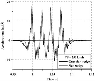
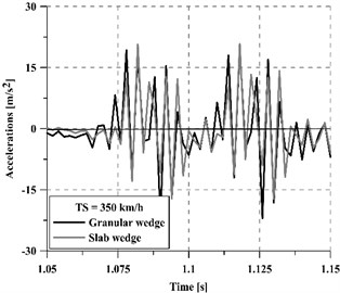
Fig. 8Accelerations on a sleeper at 250 km/h and 350 km/h train speed
a) 250 km/h
b) 350 km/h
Regardless of the vehicle speed, the concrete slab wedge reduces track vibrations more than the granular wedge, achieving a 22.5 % average reduction for 250 km/h and a 11.5 % average reduction for 350 km/h. Moreover, the mitigation capacity of the new wedge is greater on the sleeper than on the rails, especially for high vehicle speeds. In this regard, a comparative indicator has been calculated following Eq. (3) and results are summarized in Table 2:
where and are the average values of the acceleration time-histories for the case of a granular wedge and a slab wedge, respectively.
It should be pointed out that depending on the direction of the train, the transition may take place from a softer to a stiffer section (when entering the structure) or from a stiffer to a softer track section (when leaving the structure). The effect of train direction on the performance of stiffness transitions has already been studied by several authors such as [2, 15]. In this investigation, both types of transitions have been considered and their vibratory response is shown in Fig. 9. That figure presents the vibrations induced by a train running at 350 km/h, and registered over a sleeper. From the results, it can be stated that the most critical section in the whole stretch is the soft-to-stiff transition (20 %-45 % greater acceleration averaged values), which is in accordance with [15]. Thus, the transition wedge should be designed to fit the requirements of the soft-to-stiff section and, if necessary, additional mitigation measures may be placed in such a critical section.
Table 2Relative reduction of accelerations on the rail and over a sleeper
250 km/h | 350 km/h | |
21 % | 10 % | |
24 % | 13 % |
Finally, it should be noted that, although both transition wedges present good attenuation results, the transmitted vibration is smaller for the concrete slab wedge. Furthermore, since the new wedge design is built by stacking prefabricated concrete slabs, once the requirements of dynamic loads and vibrations are set, a different disposition of slabs may be placed in each transition so as to optimize construction expenses.
Fig. 9Effect of train direction (soft-to-stiff or stiff-to-soft): a) considering a granular wedge and b) the new slab-based wedge
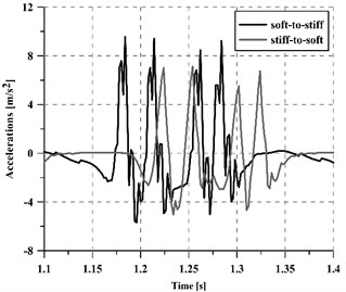
a)
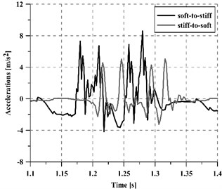
b)
Authors declare that there is no conflict of interests regarding the publication of this paper. Its aim is the publication of research results considering only academic purposes.
5. Conclusions
In this paper, the dynamic performance of a novel design of transition wedge – which would involve reduced construction costs and time- has been presented. The convenience of smoothing stiffness transitions has been assessed by comparing the behavior of the track without any wedge and two types of transition wedges: i) the widely-extended granular wedge; and ii) the proposed design, based on prefabricated concrete slabs.
Results from the investigation have been presented in terms of dynamic forces in the wheel-rail contact and vibrations in both the vehicle and the track. Furthermore, the effect of vehicle speed and direction (soft-to-stiff and stiff-to-soft) on the wedge performance has been evaluated. Therefore, the following conclusions are drawn:
1) Dynamic forces in the wheel-rail contact and accelerations in the vehicle unsprung masses are significantly higher (around 30 %) when no transition wedge is considered, which proves the convenience of using wedge transitions to smooth abrupt changes of stiffness. On the other hand, they are of similar magnitude for the case of a granular transition wedge and the slab-based wedge.
2) Vibrations on the unsprung masses of the vehicle increase (in a range 28 %-110 %) for higher vehicle speeds, regardless of the type of wedge. However, the presence of a transition wedge significantly reduces the increment of vibrations induced by higher train speeds.
3) Vibrations in the track, both on the rail and over a sleeper, are considerably smaller (i.e., between 10 %-24 %) for the slab-based transition wedge, when compared to a granular wedge. Therefore, this new wedge typology arises as a more effective and cost-efficient mitigation measure for smoothing stiffness transitions.
4) In terms of vibrations, stiffness variations from soft to stiff sections are more critical than stiff-to-soft sections, achieving up to 45 % higher average acceleration values.
References
-
Gallego I., López A., Vieira E., Rivas A. Design of Embankment-Structure Transitions for Railway Infrastructure. Proceedings of the Institution of Civil Engineers – Transport, Vol. 165, Issue 1, 2012, p. 27-37.
-
Sañudo R., Dell’olio L., Casado J. A., Carrascal I. A., Diego S. Track transitions in railways: A review. Construction and Building Materials, Vol. 112, 2016, p. 140-157.
-
Read D., Li D. Design of Track Transitions, in Research Results Digest 2006. Transportation Technology Center, Colorado, USA, 2006.
-
Koch K. Measurement of coal hopper dynamic load environment 286000-pound gross rail load unit train service – August 2004 to May 2006. Research Report R-9842007, Transportation Technology Center.
-
Varandas J. N., Hölscher P., Silva M. A. G. Dynamic behaviour of railway tracks on transitions zones. Computers and Structures, Vol. 89, 2011, p. 1468-1479.
-
Li D., And Davis D. Transition of railroad bridge approaches. Journal of Geotechnical and Geoenvironmental Engineering, Vol. 131, Issue 11, 2005, p. 1392-1398.
-
Hölscher P., Meijers P. Literature Study of Knowledge and Experience of Transition Zones. Delft, 2007.
-
Zhong X. G., Zeng X., Rose J. G. Shear modulus and damping ratio of rubber-modified asphalt mixes and unsaturated subgrade soils. Journal of Materials in Civil Engineering, Vol. 14, Issue 6, 2002, p. 496-502.
-
Real T., Zamorano C., Hernandez C., Garcia J., Real J. I. Static and dynamic behavior of transitions between different railway track typologies. Journal of Civil Engineering, Vol. 20, Issue 4, 2015, p. 1356-1364.
-
Kerr A., Moroney B. Track transition problems and remedies. AREA Bulletin 7421993, American Railway Engineering Association. p. 267-298.
-
IUR Earthworks and Track-Bed Layers for Railway Lines. UIC Code, International Union of Railways, 1994.
-
Real J. I., Zamorano C., Real T., Morales S. New transition wedge design composed by prefabricated reinforced concrete slabs. Latin American Journal of Solids and Structures, Vol. 13, 2016, p. 1431-1449.
-
Real J. I., Zamorano C., Hernandez C., Comendador R., Real T. Computational considerations of 3-D finite element method models of railway vibration prediction in ballasted tracks. Journals of Vibroengineering, Vol. 16, Issue 4, 2014, p. 1709-1722.
-
MF Recomendaciones Para el Proyecto de Plataformas Ferroviarias. Madrid, Spain, 1999.
-
Dahlberg T. Railway track stiffness variations – consequences and countermeasures. Journal of Civil Engineering, Vol. 8, Issue 1, 2010, p. 1-12.
About this article

