Abstract
Vehicle suspension is one of the important components to reduce vibration from the road. The vehicle seat suspension acts as another component to provide ride comfort, especially to reduce driver fatigues for long hour’s driving. In this paper, the ride comfort is therefore studied based on the integrated suspension model which includes vehicle chassis suspension, seat suspension and driver model. A four-DOF mathematical model is presented. The hydraulic actuator is introduced as well. Three controllers, including skyhook damper control, slide model control (SMC) and fuzzy logical control (FLC), are applied to the semi-active/active suspension with passive seat suspension. To improve the ride comfort further, combination the best performance of ride comfort from active chassis suspension, the semi-active seat suspension is then designed. The ride performance is evaluated based on driver deformation and acceleration.
1. Introduction
Suspension system is one of the important components to connect a vehicle and its wheel. It contributes to the car’s handling, braking for good active safety, driving pleasure as well as keeping vehicle occupants comfortable. Additionally, vibration transmission is reasonably well isolated by the suspension system [1]. However, the passive suspension spring and damper are not able to provide enough energy to the suspension system. In other words, they cannot produce relative motion between the body and tire. Therefore, the semi-active/active suspension system has been investigated to provide promising performance for the suppression of vehicle body vibrations. The active chassis suspension has a potential to improve the ride comfort and handling of passenger. That is the reason why there are many researchers to study it.
In order to improve the ride characteristics, many control strategies were proposed to control the active chassis suspension. LQR control scheme was used by Sam to compare the ride performance between the passive and active suspension [2]. A backstepping controller was designed by Kalsson based on the quarter car model [3]. Time delay controller (TDC) with LQR was presented by Xuan [4]. In his paper, the quarter car model is made based on the ADAMS model. The actuator model was described as well. Fuzzy controller was applied to the quarter car model to improve the characteristics of ride in Barr’s paper [5]. Sliding model controller with disturbance observer was developed by Deshpande to estimate the uncertainties and unknown road disturbance so as to improve the ride comfort [6]. controller was employed to reduce the vibration disturbance [7]. A novel control system, impedance control, was developed to control behavior of the vehicle subject to road disturbances [8]. The ride comfort performance with different active control strategies based on the quarter car model was studied by Mantars [9].
Seat suspension servers as another component to provide driver ride comfort and to reduce driver fatigue especially long hour driving or exposure to server working environment. Therefore, many researches pay much attention to the seat suspension. MR seat damper was designed to reduce vibration for commercial vehicle by Choi [10]. Tiemessen gave an overview of strategies to reduced body vibration [11]. Sun investigated the problem of control for active seat suspension [12]. In Du’s paper, although the integrated chassis suspension with driver body was presented, the seat suspension is only controlled by linear matrix inequalities with passive chassis suspension system [13].
In the literatures, most of the current studies concerning ride performance of chassis and seat suspension, both are separately studied to improve the performance of ride comfort. Integrated vehicle suspension studies are neglected; especially ride comfort comparison studies of integrated suspension are few.
In this work, four-DOF mathematical models are firstly presented including the vehicle chassis suspension, seat suspension and driver body. Based on the passive seat suspension, semi-active chassis suspension with sky-hook controller, active chassis suspension with FLC and SMC are separately employed to reduce the vertical vibration of driver body. Comparing the performance of ride comfort, the best one is chosen as basic. Then the semi-active seat suspension is designed. The standard LQR controller is considered to control semi-seat suspension with ideal model of electro-rheological damper (ER).The driver body acceleration is used to evaluate the performance of ride comfort. The active suspension system is decomposed into two loops. The desired force signal is calculated at the outer loop. For simplicity, the PID controller is then used to design the force controller with hydraulic actuator in the inner loop such that the desired force signal is achieved in a robust manner.
2. Modeling
2.1. Modeling of integrated vehicle suspension model
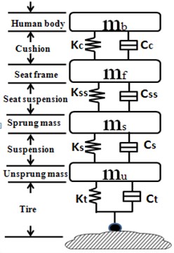
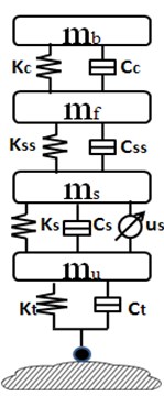
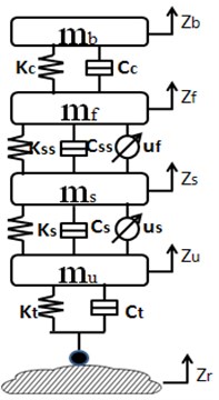
This section is to describe the integrated vehicle seat suspension model, which includes a quarter-car chassis suspension model, a seat suspension model and a driver body model. Mathematical model is built to analyze different semi-active/active suspension control strategies with/without semi-active seat suspension (Fig. 1).
Fig. 1Integrated car suspension, seat suspension and driver body model: a) passive integrated vehicle suspension without any controller, b) controlled vehicle chassis suspension with passive seat suspension, c) controlled integrated vehicle suspension
a)
b)
c)
Integrated suspension model is connected by spring and dampers. is the unsprung mass which represents the wheel assembly. is the sprung mass which represents the vehicle chassis. is the seat frame mass and is the driver body mass. , , and are the displacements of the corresponding masses, respectively. is the road displacement input. and are damping and stiffness of vehicle suspension system, respectively. and stand for compressibility and damping of the pneumatic tire, respectively., , and are damping and stiffness of seat suspension and seat cushion, respectively. and represent the active control force applied to the vehicle suspension and the seat suspension.
It is assumed that only the vertical motion of vehicle is concerned in the paper. The driver body model is assumed to be a rigid dummy mass which is rigidly contacted with the seat. Without loss of generality, the actuator is assumed to be an ideal force generator of seat suspension.
The equations of motion for integrated suspension systems are given by:
According to the above equations, the state space model of chassis suspension and seat suspension are separately developed as two functions:
where is vehicle chassis suspension, is seat suspension:
2.2. Road disturbance and hydraulic actuator system
The most road surface disturbances, including bumps, dips and small discontinuities, have been studied. In order to evaluate the performance of suspension on a typical road, an analytical model for the road input is developed based on the power spectral density (PSD) typical road. The international organization for standardization (ISO) has a series of standards of road roughness classification using power spectral density (PSD) values (ISO1982). According to the ISO, the road displacement P.S.D can be described as:
Here, is the spatial frequency (), is reference spatial frequency, . is the road displacement P.S.D, is the road roughness coefficient, and is the linear fitting coefficient, which determines the frequency structure of road spectrum, where, . The spatial spectral density can be transformed into time spectral density :
where is time frequency.
Since the road input speed power spectrum is a constant within the entire frequency range, that is, white noise [14]. Therefore, a random road roughness profile can be obtained by the white noise passing a shaping filter. The detail calculation of time domain model of road roughness excitation refers to the papers [14, 15]. In this paper the road is considered as Gaussian white noise for requirements of ride comfort. A road velocity can be constructed by passing a white noise through a low-pass filter. Mathematic modeling of road surface is given by [16]:
where is road random power, is road roughness coefficient, is vehicle velocity, is lower limit cutoff frequency of filter and is Gaussian white noise.
It is assumed that the hydraulic actuator consists of an electrical spool valve and a hydraulic cylinder. The force function of linear electro-hydraulic actuator is expressed as [4]:
where is the fluidic gain for the electrical servo, is the fluidic pressure constant.
The spool valve displacement is expressed as:
where is the valve gain, is the servo amplifier gain, is the input voltage. is valve coefficient, is supply pressure, is the piston area, is the fluid leakage coefficient, is the volume, is the volumetric elastic coefficient.
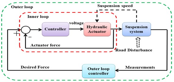
Fig. 2Controller architecture
3. Controller design
The controller architecture of active chassis suspension is decomposed into two loops in Fig. 2. The red dashed line is inner loop that tries to keep the actual force close to the desired force. The green dashed line is the main loop that the desired force signal is calculated. The dashed lines in black color represent the mechanical signal. A fully benefit of this architecture is that the inner loop can be directly utilized for the outer loop controller design.
One electro-hydraulic actuator is installed between unsprung and sprung masses, and another electro-hydraulic actuator is placed between the cabin floor and the seat frame. The effect of the actuator dynamics from seat suspension is neglected and the actuator is assumed to be an ideal force generator. PID controller is applied to actuator as an inner control loop so that actuator can track its desired force. We assume that the system does not have parameter uncertainties and measurement noises.
3.1. Sky-hook control
Skyhook damping control, introduced in 1974 by Karnopp et al. [17], is one of the most popular and implemented controllers for the semi-active suspension in commercial applications because it can dissipate system energy at a high rate. The basic idea of skyhook damping control is to link the vehicle body sprung mass to the stationary sky by a controllable ‘skyhook’ damper, which could generate the controllable force of and reduce the vertical vibrations from the road disturbance of all kinds [18]. The original work uses only one inertia damper between the sprung mass and inertia frame. The skyhook control is applicable to both semi-active systems as well as to active systems. In this study, on-off skyhook control is implemented because of simple and better suiting for the industrial application. This strategy indicates that if two velocities and are in the opposite directions, the damping force should be at the minimum value to reduce body acceleration. The damper force in the skyhook subsystem is calculated by the skyhook working principle. The semi-active skyhook control law is:
where is the nominal damping coefficient selected by the designer, is minimum value of damping coefficient, is maximum value of damping coefficient, . The relative velocity is obtained by integrating the measured relative acceleration between the sprung mass and the unsprung mass, since the accurate measurement of the absolute vibration velocity of body on a moving vehicle is very different to measure.
3.2. Slide model control
Sliding mode control theory has been applied in numbers of nonlinear systems because of its robust features. A sliding mode control can be used to handle system nonlinear behavior, mode uncertainty and external disturbance, thus it is applicable to the control of active suspension. Designing a sliding mode control is to consider the nonlinear tether system as the controlled plant, therefore defined by the general state-space in equation as:
where is the state vector, is the order of the nonlinear system, and is the input vector, is the number of inputs.
is the sliding surface of the hyper-plane, which is given in Eq. (14). Its aim is to hold the system motion on a sliding surface of:
In order to obtain a stable solution of the system, it must stay on this surface, i.e. , is a positive constant referred to as the sliding surface slope which strongly affect the rate of error convergence. The detailed design processes could be found in [19].
3.3. Fuzzy logic controller design
Fuzzy control, developed by L. A. Zadeh [20], is a practical alternative for a variety of challenging control applications since it provides a convenient method for constructing nonlinear controllers via the use of heuristic information. The fuzzy logic control’s rule-base comes from an operator’s experience that has acted as a human-in-the-loop controller. It actually provides a human experience based on representing and implementing the ideas that human has about how to achieve high-performance control. The synthesis of FLC can be designed in accordance with four steps: 1) a fuzzification interface, 2) an “if-then” rule-base, 3) an inference mechanism and 4) a defuzzification interface. The active control of suspension is constructed by using fuzzy reasoning shown in Fig. 3. The velocity and acceleration of the sprung mass are inputs of fuzzy controller. The output of the controller is force from actuator. Here, is the velocity error of sprung mass, is the derivative of.
Fig. 3Fuzzy logic control workflow diagram of vehicle suspension system
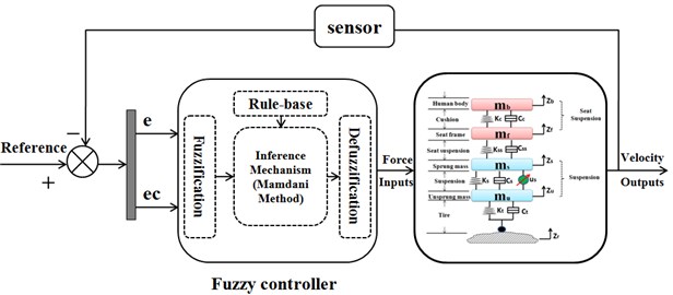
Fig. 4Triangular-shaped membership functions for FLC controller
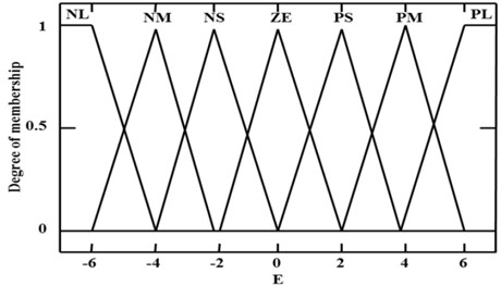
The first step in making a fuzzy logic control is to map variable from practical space to fuzzy space. In other words, a fuzzification interface converts controller inputs into information (fuzzy set) so that the inference mechanism can easily use to active and apply rules. A numerical value of input is to be fuzzied so that the fuzzification of the input becomes a membership function to be evaluated. The triangular–shaped membership function is selected, because they are very basic and widely used. The universe of discourse for the both input variables is divided into seven grades based on the following linguistic variables, negative large (NL), negative middle (NM), negative small (NS), zero (ZE), positive small(PS), positive middle (PM), positive large (PL) in a range of [–6-6]. The membership functions of positive, negative are selected so that they cover large bounds of uncertainties. While defuzzification is a mapping from the fuzzy control actions (fuzzy space) into a space of the non-fuzzy control action (practical space). In the FLC for active suspension system, the seven elements in the fuzzy sets for one output of FL are applied as well which are the same as inputs of Error () and Error-in-Change (). The used membership functions for the fuzzy control are triangular for the input and output variables, respectively, see Fig. 4.
The relationship between two inputs of the Error () and Error-in-Change () with one output of the active control force () are defined by the rule base. The fuzzy control rules are designed by a collection of if-then rules. A rule-base contains a fuzzy logic quantification of the expert's linguistic description of how to achieve good control. In other words, the “if-then” rule-based is employed to describe the experts’ knowledge. The relationship between 2 inputs of the error (E) and the change in error (EC) with 1 output of the active control force (U) can be defined by the FLC rule-based could map, which presents mapping of fuzzy rules in the control space. The FLC rule-base is characterized by a set of linguistic description rules based on conceptual expertise which arises from typical human situational experience. Using the linguistic variables, the 49 fuzzy rules are defined based on the human situational experience. The rule-based for the ride comfort of the four-DOF suspension system is shown in the format of a lookup Table 1, which came from previous experience gained for the active force control during body acceleration changes for ride comfort. By using basic engineering sense, these rules are developed. Briefly, the main linguistic control rules are that the body acceleration is a propositional function of suspension actuator force. In other words, the active force is increased with body acceleration increasing, vice versa. The type of fuzzy control rules are: If E is NL, EC is NL then U is PL.
Table 12-in-1-out FLC rule table for active suspension
U | EC | |||||||
E | NL | NM | NS | ZE | PS | PM | PL | |
NL | PL | PL | PM | PS | PS | PS | ZE | |
NM | PL | PM | PS | PS | PS | ZE | NS | |
NS | PM | PS | ZE | ZE | ZE | ZE | NM | |
ZE | PM | PS | ZE | ZE | ZE | NS | NM | |
PS | PM | PS | ZE | ZE | ZE | NS | NM | |
PM | PS | ZE | ZE | ZE | ZE | NM | NL | |
PL | ZE | NS | NS | NS | NM | NL | NL | |
Note: N: negative, P: positive, L: large, M: middle, S: small, ZE: zero | ||||||||
Fig. 52-inputs-1-out FLC inference system
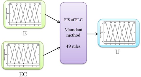
An inference mechanism emulates the expert’s decision making in interpreting and applying knowledge about how the best to control the plant. In this paper, the input variables to the fuzzy control are velocity and acceleration of chassis suspension, the Fuzzy Inference System (FIS) of Mamdani-type inference for the FLC is selected to defuzzificate output shown in Fig. 5. A detailed analysis and description of the fuzzy logic control of suspension systems can be found in [1, 5, 19].
4. Numerical simulations
In the first subsection, three control strategies are used to the chassis suspension system combination of passive seat suspension system. The ride comfort performances are compared. The best performance is chosen as basic. Then the semi-active seat suspension is designed combination the best performance of active suspension in the second subsection. The parameters used in the simulations are listed in Table 2.
Table 2Parameters of vehicle model
Mass (kg) | Damping coefficient (Ns/m) | Spring stiffness (N/m) | |||
36 | 400 | 160000 | |||
240 | 1400 | 16000 | |||
20 | 1080 | 7414.86 | |||
70 | 152.8 | 8228.78 | |||
4.1. A quarter-car model with passive seat suspension
The four-DOF semi-active and active suspension is studied based on the skyhook controller, SMC and FLC. The performance of ride comfort is compared. The vertical acceleration of the human body is used to evaluate the performance of ride comfort.
Fig. 6Comparison driver body acceleration response with Skyhook, SMC vs. FLC control methods
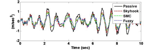
a) Driver body acceleration
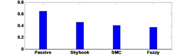
b) RMS of vertical driver body acceleration
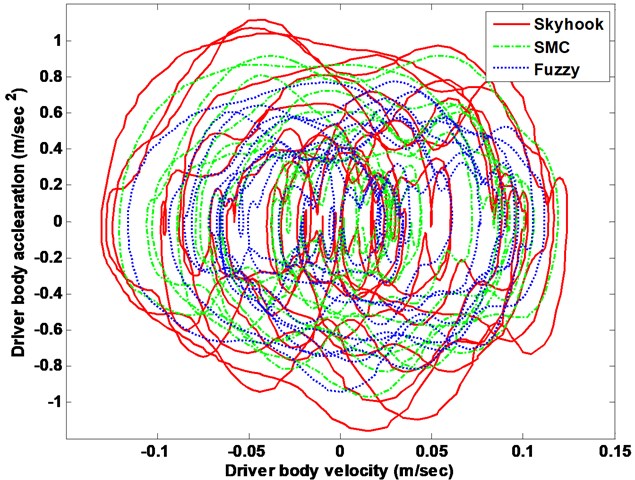
The drive body acceleration is compared with passive, skyhook controller, SMC and FLC, shown in Fig. 6. The root-mean-squire (RMS) acceleration is calculated as well to elaborate its histogram displayed in bottom of Fig. 6. The driver body deformation is presented as well given in Fig. 7. From the comparison results, the FLC has better performance in isolating road vibration than the two other controller approaches. The Fig. 8 shows the phase plot, body velocity against body acceleration. Obviously, the FLC controller goes faster convergence which corroborates the fuzzy active suspension system controllable steady-state. Therefore, the FLC active suspension is selected as basic. Then the semi-active seat suspension is designed.
Fig. 7Driver body deformation response with Skyhook, SMC vs. FLC control methods
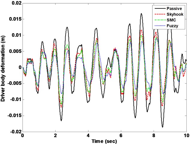
Fig. 8Suspension system driver body response phase plot
4.2. A quarter-car model with semi-active seat suspension
In order to improve the further performance of ride comfort, the semi-active seat suspension is designed based on the active suspension system (fuzzy controller). The stander LQR controller is employed to the semi-active seat suspension. The LQR controller designed is not presented in this paper. The more details see in [4]. A quarter car models with a semi-active seat suspension model and driver model are shown in Fig. 1(c). The parameters are the same in the Table 2.
Fig. 9Comparison comfort performance with respect to the passive system
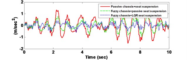
a) Driver body acceleration
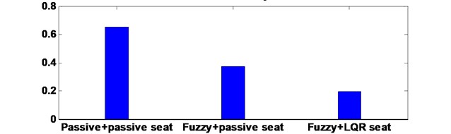
b) RMS of vertical driver body acceleration
Fig. 10Suspension system body acceleration response in frequency domain
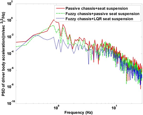
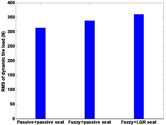
The driver body acceleration under the white noise road disturbance is shown in Fig. 9. The histogram is given as well in bottom of Fig. 9. It can be seen that the proposed control strategy largely reduces the driver body acceleration compared to the passive system, and therefore, achieves good performance of ride comfort. Fig. 10 shows the driver body acceleration amplitude in frequency domain. It gives that all the state, FLC with passive seat frame and FLC with semi-active seat suspension, can reduce at two of the key resonance peak points around 100 Hz. It also shows that the FLC with semi-active seat suspension has the best control effects on 4-DOF suspension system compared with semi-active/active chassis suspension and passive suspension system. The phase plot shows the FLC+LQR can converge quickly in Fig. 11. Fig. 12 shows that the active control methodologies improve the ride comfort but the tire load is increased as well.
Fig. 11Suspension system body response phase plot
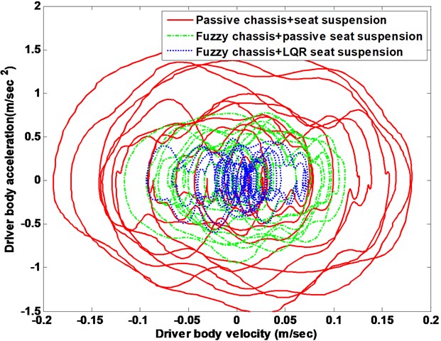
Fig. 12Comparison root-mean-square of tire load
5. Conclusions
In this paper, the ride comfort of integrated suspension system is studied based on the skyhook-damping, slide model control and fuzzy logic control. Firstly, the semi-active/active chassis suspension is designed with passive seat suspension to improve the ride performance employing skyhook damper, SMC and FLC. The best ride comfort performance is then chosen as bases to apply the integrated suspension. Secondly, the integrated suspension, active fuzzy suspension with LQR semi-active seat suspension, is employed to improve the ride comfort performance. Numerical simulations are used to compare the performance of the designed controllers. The results show that the integrated suspension control can provide better ride comfort performance. Integrated suspension controller method obtain the desired results, however, the uncertainties are not considered in the paper, therefore, further study on the control of the integrated model, considering more complex car models, for example, parameter uncertainties, measurement noise and time varying parameters, will be conducted.
References
-
Nan Y. H., Xuan D. J., Kim J. W., Ning Q., Kim Y. B. Control of an active suspension based on fuzzy logic. International Conference on Computer and Electrical Engineering, 2008, p. 303-307.
-
Sam Y. M., Ghani M. R. A., Ahmad N. LQR controller for active car suspension. TENCON 2000 Proceedings, Vol. 1, 2000, p. 441-444.
-
Karlsson N., Teel A., Hrovat D. A backstepping approach to control of active suspensions. Proceedings of the 40th IEEE Conference on Decision and Control, 2001, p. 4170-4175.
-
Xuan D. J., Kim J. Z., Nan Y. H., Kim Y. B. Time delay force control for vehicle active suspension system. Proceedings of the 26th Chinese Control Conference, 2007, p. 640-645.
-
Barr A. J., Ray J. I. Control of an active suspension using fuzzy logic. Proceedings of the 5th IEEE International Fuzzy Systems, 1996, p. 42-48.
-
Deshpande V. S., Bhaskara M., Phadke S. B. Sliding mode control of active suspension systems using a disturbance observer. 12th International Workshop on Variable Structure Systems, 2012, p. 70-75.
-
Yamashita M., Fujimori K., Hayakawa K., Kimura H. Application of H∞ to activesuspension systems. Automatica, Vol. 20, Issue 11, 1994, p. 1717-1729.
-
Fateh M. M., Alavi S. S. Impedance control of an active suspension system. Mechatronics, Vol. 19, Issue 1, 2009, p. 134-140.
-
Mantaras D. A., Luque P. Ride comfort performance of different active suspension systems. International Journal of Vehicle Design, Vol. 40, Issues 1-3, 2006, p. 106-125.
-
Choi S. B., Ham M. H., Lee B. K. Vibration control of a MR seat damper for commercial vehicle. Journal of Intelligent Material Systems and Structures, Vol. 11, Issue 12, 2000, p. 936-944.
-
Tiemessen I. J., Hulshof C. T. J., Fringsdresen M. H. W. An overview of strategies to reduce whole-body vibration exposure on drivers: A systematic review. International Journal of Industrial Ergonomics, Vol. 37, Issue 3, 2007, p. 245-256.
-
Sun W., Li J., Zhao Y., Gao H. Vibration control for active seat suspension systems via dynamic output feedback with limited frequency characteristic. Mechatronics, Vol. 21, Issue 1, 2011, p. 250-260.
-
Du H., Li W., Zhang N. Vibration control of vehicle seat integrating with chassis suspension and driver body model. Advances in Structural Engineering: an International Journal, Vol. 16, Issue 1, 2013, p. 1-9.
-
Chen X., Li G. F. Study of ride comfort of automobile semi-active suspension based on the interaction of passenger vehicle road. International Conference on Computer Application and System Modeling, 2010.
-
Taghirad H., Esmailzadeh E. Automobile passenger comfort assured through LQG/LQR active suspension. Journal of Vibration and Control, Vol. 4, Issue 5, 1998, p. 603-618.
-
Truscott A. J., Burton A. W. On the analysis, modeling and control of an advanced automotive suspension system. International Conference on Control, Vol. 1, 1994, p. 183-189.
-
Karnopp D. C., Crosby M. J., Harwood R. A. Vibration control using semi-active force generators. Journals of Engineering for Industry, Transactions of the ASME, Vol. 94, 1974, p. 619-626.
-
Savaresi S. M., Silani E., Bittanti S. Acceleration-Driven-Damper (ADD): An optimal control algorithm for comfort oriented semi-active suspensions. ASME Transactions, Journal of Dynamic Systems, Measurement and Control, Vol. 127, Issue 2, 2005, p. 218-229.
-
Chen Y. Skyhook surface sliding mode control on semi-active vehicle suspension system for ride comfort enhancement. Engineering, Vol. 1, Issue 1, 2009, p. 23-32.
-
Zadeh L. A. Fuzzy sets. Information and Control, Vol. 8, 1965, p. 338-353.
About this article

