Abstract
Multiple-damage-inflicted scattering signals usually overlap with each other due to Lamb wave dispersion and multi-mode characteristics. As a result, it is difficult to accurately distinguish damages that occur relatively close to each other using the conventional ultrasonic phased array method. In order to solve this problem, an improved linear mapping (ILM) dispersion compensation method is proposed and is applied to enhance the ultrasonic phased array monitoring resolution. Through a uniform linear array arrangement, the damage scattering signals are collected in a round-robin pattern of ultrasonic phased array, and then compensated based on the linear relation wavenumber curve from actual measurement. At last, the scan can be obtained by monitoring the energy scattered by the damages using delay-and-sum method. To verify the proposed method, experiments are performed on an aluminum (LY-12) plate. Two results of multiple artificial damages show that the proposed method can effectively compensate the dispersion characteristics of Lamb waves. The direction estimation error and distance estimation error are less than 4° and 2 cm, respectively.
1. Introduction
Structural health monitoring (SHM) is an area of growing interest and worthy of new and innovative approaches. Lamb waves offer a number of advantages in SHM applications, especially in those situations where large areas of plate structures are to be monitored. Many literatures have focused on the research methods of Lamb waves, including the delay-and-sum method [1, 2], the time reverse based imaging technique [3-5], spatial filter method [6, 7] and ultrasonic phased array method [8, 9].
Ultrasonic phased array technique is one of the methods of active Lamb waves based SHM. The performance of a SHM system can be enhanced by means of active ultrasonic phased arrays due to their superior signal-to-noise ratio and beam-steering capability [10]. The basic principle of ultrasonic phased array technology has been studied theoretically and experimentally in the structural damage monitoring for aircraft plate structures. Giurgiutiu and Yu [11, 12] studied the ultrasonic phased array imaging principle of linear array and two-dimensional arrays, and realized single crack detection on aluminum plates using linear array and rectangular ultrasonic phased array. Wilcox et al. [13, 14] discussed circular omni-directional guided wave phased arrays and realized single damage detection on aluminum plates. Yoo et al. [15] worked on the phased array algorithm based on spiral array and detected two types of damage (rubber patch and crack) in the composite material. Yuan et al. [16] applied linear ultrasonic phased array and detected single damage on aluminum, composite materials and some kind of complex structures. Malinowski et al. [17] put forward the improvement of star-shaped configuration and merged multiple linear phased array imaging results to realize double cracks detection at about 30° and 135° on aluminum. Yan et al. [18] presented circular phased array imaging approach and realized multiple damages detection including one 5 mm diameter hole at 0°, three notches at about 0°, 225° and 300° respectively, and a set of six 3 mm diameter holes at 270°. The distance of the hole and the notch at 0° is more than 200 mm, so the two damages can be distinguished clearly. However, since the distance in between the six 3 mm diameter holes is less than 35 mm, they looked combined as a line in the resulting scanning image.
Ultrasonic phased array testing for SHM is complicated because of the dispersion nature of the Lamb wave modes. Scattered waves become weak in amplitude due to geometric spreading and may possibly present various interferences and overlapping arrival times, especially for long distance testing. In comparison with the case of single damage, much more intricate dispersion phenomena often happen in the captured signals of multiple-damage detection. This makes the prognosis for multiple damages highly uncertain, because the scattered wave components by the damages considerably superpose and frequently interfere with each other. Such phenomenon is found more severe in composite structures or in structures with irregular boundary conditions [19]. The concept of arrival time may become ill-defined due to the strong dispersion. Thus, ultrasonic phased array prediction based on an individual signal may fail to ascertain the correct number of damage sites, not to mention the location and severity of damages, especially for that of smaller in-between distances.
In order to detect multiple damages more accurately by means of ultrasonic phased array technology, different methods have been proposed to compensate dispersion. The two main methods are time-distance domain transformation method and Linear Mapping (LM) method. Wilcox et al. [20] adopted time-distance domain transformation for phased array imaging. The basic idea underlying the dispersion compensation is very similar to the time reversal procedure presented by Xu and Giurgiutiu [21]. The signal recorded at the receiver side is time reversed and propagated back to the source, which is then compressed to its original shape. Liu and Yuan [22] proposed a dispersion removal procedure based on the wavenumber linear Taylor expansion. By transforming a dispersed signal to frequency domain and interpolating the signal at wavenumber values satisfying the linear relation, the original shape of the signal can be recovered. Xu and Giurgiutiu [21] compared the time-distance domain transformation and the linear mapping method, and adopted the latter to improve the resolution of phased array.
However, both the time-distance domain transformation and the linear mapping method require theoretical models to plot the corresponding wavenumber curve. In real applications, the parameters that characterize the structural property of the material are unknown. This in turn means that the theoretical wavenumber curve cannot be obtained directly.
In order to monitor multiple damages accurately using ultrasonic phased array technology, improved linear mapping (ILM) dispersion compensation algorithms are proposed in this paper. It is similar to the linear mapping material dispersion compensation method, but is based on the actual measurement of the wavenumber curve. The damage-induced scattering signals can be compensated by relying on the calculated wavenumber curve. The experimental results on the aluminum plate show that this method can not only improve the imaging resolution and SNR of ultrasonic phased array, but also enhance the accuracy of damage localization on closely-positioned damages.
2. Classical phased array theory
The uniform linear piezoelectric transducer (PZT) array consists of elements. The PZT elements in the array are equally spaced at distance (, : ultrasonic wavelength). The wave pattern generated by the phased array is the result of the superposition of the waves generated by each individual PZT element. By sequentially activating the individual elements of an array transducer at slightly different times, the ultrasonic wavefront can be focused or steered in a specific direction.
The wave front in far field of a linear PZT array is shown in Fig. 1. For a distant point , is the distance from point to coordinate system origin. Because , the rays connecting the point with the sensors can be considered with a parallel fascicle of . The origin of coordinate system is set on the mid-point of the PZT array. The point on the Cartesian coordinate system of th PZT element is denoted as (, 0), 0,…, 1, where .
Fig. 1Schematic diagram of phased array
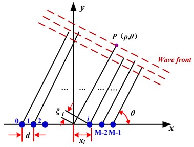
As signals are transmitted from each of the array elements, point receives the superposed signal from the excitation signals that traveled a certain distance onto the plate. Then the total signal received at point is:
where represents the decrease in the wave amplitude due to directional radiation; represents the excitation signal; is the time delay experienced as the signal travels from the origin to the point ; and is the Lamb wave speed traveling in the structure.
For the th PZT element, the distance will be shortened by . If all the PZT elements are excited simultaneously, the signal from the th PZT element will arrive at point earlier by , 0,…, 1.
If the PZT elements are not excited simultaneously, but with some individual delays, then the total signal received at point will be:
If the time delay equals the time difference, namely: 0,…, 1, the signal energy received at point reaches a maximum, which is times stronger with respect to that of a single sensor. The signal of the maximum beam directed at angle , onto point is expressed as:
If the time delay , the beam array is rotated at angle about the -axis. Thus, the formation of a beam directed at angle is achieved by controlling the delay in the excitation of the PZT elements.
Similar beamforming principles are applied to receivers in the same way as to transmitters. If the reflected signals can be received by all the sensors by a delay of , the synthetic signal will be times stronger than that obtained by the individual sensor.
3. Phased array technology improved by ILM dispersion compensation algorithm
When PZT elements are used as actuators and sensors, the Lamb waves signal can be written in the frequency domain as:
where – wave propagation distance, – angular frequency, – electro-mechanical efficiency coefficient of PZT wafers, – mechanical-electro efficiency coefficient of PZT wafers, – the structure transfer function.
Considering that only one mode ( or) is excited in the structure, the transfer function can be simplified into [23, 24]:
where , and are the amplitude, imaginary number and the wavenumber of the respective modes.
Inserting Eq. (5) into Eq. (4) yields:
In the propagation of Lamb waves, the spatial phase of is shifted by the phase-delay factor . For the dispersive Lamb waves, is nonlinear with respect to , which can be expanded in a Taylor series in the frequency as:
The Lamb waves with nonlinear wavenumber causes phase distortions and results in a dispersive waveform. However, if the wavenumber is linearly related to , there will be no dispersion in the propagated waveform. In the Eq. (7), when the first two terms of the expansion are nonzero, the linear wavenumber relation is approximated as:
where and are the phase velocity and group velocity, respectively.
According to the relationship between and , the nonlinear index mapping relationship between and of Eq. (6) is replaced by the linear index mapping relationship of Eq. (8) to realize dispersion compensation. Since the processing is carried out in the same frequency, fast Fourier transform and its inverse transform algorithm are used to improve the efficiency of the implementation.
4. The process of improved phased array technology for multiple damages detection
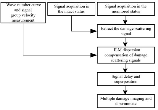
The process of multiple damages detection is explicitly depicted in Fig. 2. The method is listed as follows:
1) Defining the wavenumber curve .
A narrowband excitation signal with center frequency ωc is selected to excite any of the line array’s PZT elements, and the th piezoelectric element receives signal away from the line array. The direct wave signal of mode can be extracted by adding rectangular window in the received signal. The frequency-wavenumber curve can be expressed as:
where is the phase difference between the sensor signal direct wave packet and excitation signal wave packet, is the signal propagation distance. can be calculaed as:
wherein represents the real part of ( represents the frequency response of the excitation signal, represents the frequency response of the sensor signal after extracting the direct wave), represents the imaginary part of . refers to the arctangent function. refers to the range of .
Fig. 2The process of multiple damages detection
2) The measurement of group velocity.
Another narrowband excitation signal is selected, whose center frequency is ωc, to excite any PZT elements on the line array, and the th piezoelectric element receives signal outside of the line array. The group velocity of the signal is given by:
where is the difference time between peak values of excitation signal and the sampling zero, is the difference time between the peak values of response signal and the sampling zero.
3) The acquisition of health signals.
Health signals refer to the sensor signals in the intact status. Data acquisition is carried out in a round robin way, scanning from 0° to 180°. When one of the PZT elements works as the actuator, the others serve as the sensors. The center frequency of excitation signal is .
4) The acquisition of damage signals.
The sensor signals in the monitored status are called as damage signals. Data acquisition is also carried out in a round robin way, scanning from 0° to 180°. When one of the PZT elements works as the actuator, the others serve as the sensors. The center frequency of excitation signal is .
5) The acquisition of damage scattering signals.
The differential signals between health signals and damage signals are called damage scattering signals, where and denote the actuator index and sensor index.
6) ILM dispersion compensation method is used to compensate dispersion of damage scattering signals. This is done by:
① Applying an FFT to the narrow band excitation signal and then obtaining its ;
② Performing an FFT on the damage scattering signal to obtain ;
③ Using Eq. (7) to calculate linear wavenumber values klin ();
④ Calculating the damage scattering signal under the linear wavenumber.
Each frequency value changes to according to the linear wavenumber values, as shown in Eq. (11), where is the inverse function of the wavenumber values :
The nonlinear transformation relationship between and causes the dispersion phenomenon, as expressed by Eq. (6). Hence according to the relationship between klin () and , the dispersion compensation signal can be obtained by Eq. (13):
In order to eliminate the effect of excitation signal spectrum , needs to be multiplied by compensation factor :
Applying IFFT to , can be obtained, as follows:
7) The delay and sum of scattering signals.
The compensated scattering signals are in turn delayed in phase and are superimposed based on the scanning angle. And the synthetic signal on each angle can be calculated by:
where and represent the actuator index and the sensor index, respectively. represents the decrease in the wave amplitude due to the directional radiation; is the additional time delay of the damage scattering signal received by each sensor:
8) The damage localization and imaging.
When the signal beam points at the direction towards the damage location, all signals will be focused, and the energy of combined signal will be enhanced. Subsequently, the signal energy reflected by damage is also the strongest in this direction. Any information regarding damage angle can be obtained based on this principle. The damge distance ρ can be calculated as:
where is the arrival time of the signal directed to the damage, is the Lamb wave velocity at the structure.
To conclude, the damage location can be achieved from the scanning direction and the calculated distance.
The energy (amplitude) of the signal can be expressed in terms of its distance and direction, which in turn is a function of time and angle respectively. Meanwhile, the scanning image can be obtained by displaying the energy of synthetic signal and hence the damage can be clearly characterized on the scanning image.
5. Experimental verification
5.1. Experimental system
A piezoelectric multi-channel structural health monitoring scanning system [25, 26] is utilized for all the experiments. Fig. 3 shows the experimental system setup.
Fig. 3Experimental setup
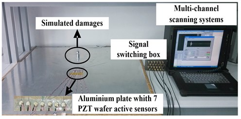
Fig. 4Sensors array layout diagram (mm)
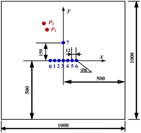
As seen from Fig. 4, the dimension of LY-12 aluminum plate is 1000 mm×1000 mm×2 mm. The uniform linear PZT array consists of seven circular elements with 8 mm labeled 0 to 6 with a spacing 12 mm. The center of the PZT array is set as the origin point, and the PZT linear array itself as axis. The 7th element is placed on the axis, 150 mm away from the origin point, to measure the wavenumber curve of the structure and the group velocity of ultrasonic signal. A 2 kg mass with 20 mm diameter is used to simulate as the artificial damage.
5.2. Multiple damages detection based on improved phased array technology
The narrow band 5-cycle modulated sine signal works as the excitation signal, which has an amplitude of 50 V and central frequency of 40 kHz. The mode sensor signal amplitude dominates the mode sensor signal amplitude, which is conducive to the signal analysis. The sampling frequency is set to 2 MHz, and 1600 points are collected.
The positions of the PZT elements and damage locations are shown in Fig. 4. Actual damage points (300 mm, 100°) and (350 mm, 100°) in polar coordinates are taken as example.
Based on the principle of phased array, this paper discusses an improved data collection method that facilitates scanning of any angle within the range of 0°-180°. For both intact status and the monitored status, data collection is conducted in a round-robin pattern. During each data collection process, one of the seven actuators is selected to send out excitation while the rest serve as sensors to pick up the scattering signals. Every PZT element will take turns to serve as actuators. Upon the completion of the round-robin data collection, a total of 7×6 = 42 signals are recorded.
The experiment is set up such that the first piezoelectric element works as an actuator, while the sixth works as a sensor. The recorded health signal and the damage signal are shown in Fig. 5(a) and 5(b). The damage scattering signal, which is the difference of the health signal and the damage signal, is shown in Fig. 5(c). As seen from Fig. 5(c), crosstalk interference is the reason for the first wave packet. The superposed damage scattering signal is set behind. The resulting waveform is complicated, which makes it difficult to identify the actual multiple damages.
Fig. 5The sensor response signal and the damage scattering signal

a) Health signal

b) Damage signal

c) Damage scattering signal
Fig. 6Scanning image of multiple damages
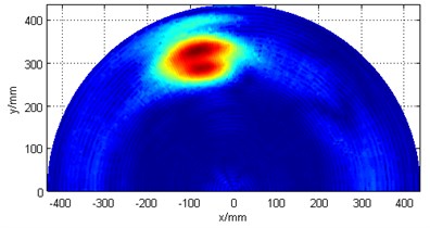
Fig. 6 shows the image scanned using the conventional ultrasonic phased array technology. It can be seen that the scattered properties make the damage points enlarged and damage boundary fuzzy, therefore making it difficult to identify the predetermined multiple damages from the scanning image.
In order to improve the quality of the damage scanning, the method combining ultrasonic phased array technology and dispersion compensation imaging is adopted to identify multiple damages.
The 5-cycle modulated sine signal with center frequency 40 kHz is selected as the excitation signal, which excites the third PZT element to generate Lamb waves in the structure. The seventh piezoelectric element receives signal.
Then the wavenumber curve is plotted. Rectangular window on the sensor signal is added to extract the direct arrival wave of mode. The wavenumber curve can be generated based on Eqs. (9) and (10), as shown in Fig. 8. The dotted line in Fig. 8 is the linear wavenumber curve.
Afterwards, the group velocity is calculated as 1621 m/s by Eq. (11).
Finally, the health signals are obtained.
Fig. 7Wavenumber curve
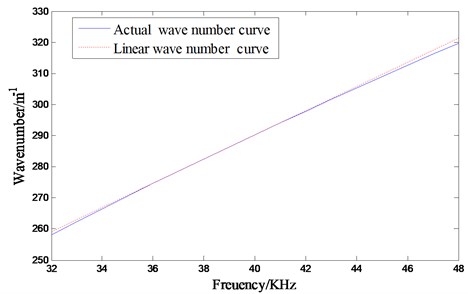
Fig. 8The process of damage scattering signal dispersion compensation
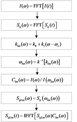
The damage signals are first obtained by taking the difference between the damage signals and health signals. Then, the dispersion of the damage scattering signals of each piezoelectric sensor is compensated by means of the process depicted in Fig. 8, the ILM dispersion compensation method.
Fig. 9Damage scattering signals
a) Original damage scattering signal
b) Damage scattering signal after dispersion removal
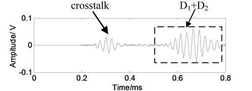
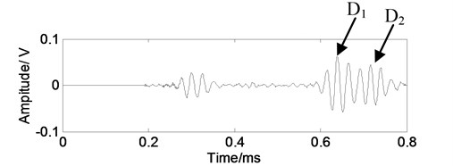
Remember that in this experiment, the first PZT element works as the actuator, while the sixth works as the sensor. The signals before and after dispersion compensation are shown in Fig. 9. As it can be seen from the Fig. 9(b), the obtained wave packets of mode dispersion signal gets compressed. Also, the duration of wave packets in time domain gets shorter, hence the shape of the wave packet is more focused. The two damage scattering signals and can be clearly distinguished from each other.
is the synthetic signal of every angle, which is taken from the compensated damage scattering signals after conducting delay-and-sum method, as expressed by Eq. (16) and Eq. (17). From Fig. 10, ( 0, 1,…, 6) is the sum of all damage scattering signals after dispersion compensation and delay, where the th PZT element works as an actuator and the others work as sensors in 100° direction. is the ultimate synthetic signal.
Fig. 10Synthetic signals of scattering signals
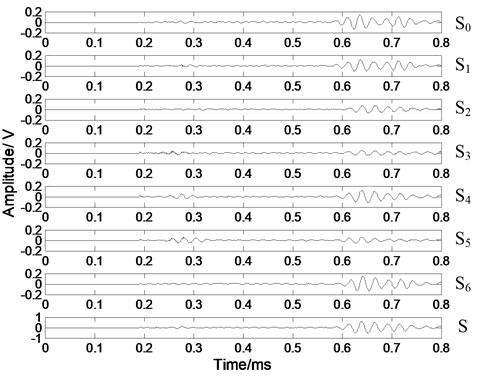
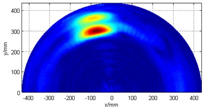
Fig. 11 shows the scan of the damages obtained using ultrasonic phased array technology and dispersion compensation imaging method. The two damages can be clearly distinguished from the image, the results are (309 mm, 103°) and (364 mm, 104°) based on the polar coordinates. The error in direction estimation is less than 4°, and that of the distance estimation is less than 2 cm, when compared with actual results (300 mm, 100°) and (350 mm, 100°). It is shown that the ILM method can improve the imaging resolution of the conventional ultrasonic phased array technology.
Fig. 11Damages’ scanning image
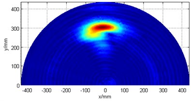
Two other artificial damages at (310 mm, 90°) and (280 mm, 100°) are also taken as example. Conventional ultrasonic phased array technology without dispersion compensation cannot separate these two damage intuitively, and only one damage can be observed in the scan (Fig. 12(a)). However, after applying dispersion compensation, both damages are detected (Fig. 12(b)). Damage detection results are (312.7 mm, 91°) and (281.7 mm, 103°) based on polar coordinates. The maximum error in direction estimation is 3°, while that of distance estimation is 1.48 cm.
Fig. 12Damages’ scanning image
a) Without dispersion compensation
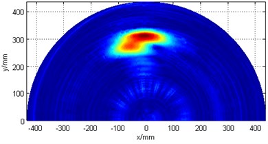
b) With dispersion compensation
6. Conclusions
The dispersion characteristics of Lamb wave causes the received signal packets to elongate, makes the scattering signals from multiple damages overlap with each other, and consequently deteriorates the spatial resolution of the damages. This paper investigates a multiple damage detection method based on piezoelectric ultrasonic phased array technology and ILM dispersion compensation using compact array of PZT elements.
The performance of the proposed method is verified on an aircraft aluminum plate structure. Results show that the conventional ultrasonic phased array method cannot effectively identify closely located multiple damages from the scan image. However, the combination of this method with ILM dispersion compensation successfully distinguishes closed-placed multiple damages. The results of two artificial multiple damages have shown that the proposed method can effectively compensate the dispersion characteristics of Lamb waves. A good performance is obtained with the direction estimation error and distance estimation error less than 4° and 2 cm, respectively.
References
-
Michaels J. E., Michaels T. E. Guided wave signal processing and image fusion for in situ damage localization in plates. Wave Motion, Vol. 44, Issue 6, 2007, p. 482-492
-
Lhn J., Chang F. Pitch-catch active sensing methods in structural health monitoring for aircraft structures. Structural Health Monitoring, Vol. 7, Issue 1, 2008, p. 5-19.
-
Wang C. H., Rose J. T., Chang F. K. A synthetic time-reversal imaging method for structural health monitoring. Smart Materials and Structures, Vol. 13, Issue 2, 2004, p. 415-423.
-
Wang L., Yuan F. Damage identification in a composite plate using pre-stack reverse-time migration technique. Structural Health Monitoring, Vol. 4, Issue 3, 2005, p. 195-211.
-
Wang Q., Yuan S. Baseline-free imaging method based on new PZT sensor arrangements. Journal of Intelligent Material Systems and Structures, Vol. 20, Issue 14, 2009, p. 1663-1673.
-
Wang Y., Yuan S., Qiu L. Improved wavelet-based spatial filter of damage imaging method on composite structures. Chinese Journal of Aeronautics, Vol. 24, Issue 5, 2011, p. 665-672, (in Chinese).
-
Purekar A. S., Pines D. J., Sundararaman S., Adams D. E. Directional piezoelectric phased array filters for detecting damage in isotropic plates. Smart Materials and Structures, Vol. 13, Issue 4, 2004, p. 838-850.
-
Clarke T., Cawley P., Wilcox P. Evaluation of the damage detection capability of a sparse-array guided-wave SHM system applied to a complex structure under varying thermal conditions. IEEE Transactions on Ultrasonics, Ferroelectrics, and Frequency Control, Vol. 56, Issue 12, 2009, p. 2666-2678.
-
Giurgiutiu V., Bao J., Zhao W. Piezoelectric wafer active sensor embedded ultrasonics in beams and plates. Experimental Mechanics, Vol. 43, Issue 4, 2003, p. 428-449.
-
Yuan S. Structural Health Monitoring. National Defence Industry Press, Bei Jing, 2007, (in Chinese).
-
Giurgiutiu V. Structural Health Monitoring with Piezoelectric Wafer Active Sensors. Academic Press, 2007.
-
Yu L., Giurgiutiu V. Design, implementation, and comparison of guided wave phased arrays using embedded piezoelectric wafer active sensors for structural health monitoring. Smart Structures and Integrated Systems, Vol. 6173, 2006, p. 1-12.
-
Wilcox P. D. Omni-directional guided wave transducer arrays for the rapid inspection of large areas of plate structures. IEEE Transactions on Ultrasonics, Ferroelectrics and Frequency, Vol. 50, Issue 6, 2003, p. 699-709.
-
Holmes C., Drinkwater W., Wilcox D. Advanced post-processing for scanned ultrasonic arrays: Application to defect detection and classification in non-destructive evaluation. Ultrasonics, Vol. 48, Issue 6-7, 2008, p. 636-642.
-
Yoo B., Purekar A., Pines D. J. Piezoceramic-based 2D spiral phased array and multiple actuators for structural health monitoring: thin isotropic panel with straight boundaries. Journal of Intelligent Material Systems and Structures, Vol. 22, Issue 12, 2011, p. 1327-1343.
-
Sun Y., Yuan S., Cai J. Using phased array technology in structure health monitoring. Journal of Astronautics, Vol. 29, Issue 4, 2008, p. 1393-1396, (in Chinese).
-
Malinowski P., Wandowski T., Trendafilova I., Ostachowicz W. a phased array-based method for damage detection and localization in thin plates. Structural Health Monitoring, Vol. 8, Issue 1, 2009, p. 5-15.
-
Yan F., Roger R. L., Rose J. L. Ultrasonic guided wave imaging techniques in structural health monitoring. Journal of Intelligent Material Systems and Structures, Vol. 21, Issue 3, 2010, p. 377-384.
-
Su Z., Wang X., Chen Z., Ye L. A hierarchical data fusion scheme for identifying multi-damage in composite structures with a built-in sensor network. Smart Materials and Structures, Vol. 16, Issue 6, 2007, p. 2067-2079.
-
Fromme P., Wilcox P. D., Lowe M. J. S., Cawley P. On the development and testing of a guided ultrasonic wave array for structural integrity monitoring. IEEE Institute of Electrical and Electronics, Vol. 53, Issue 4, 2006, p. 777-785.
-
Xu B., Yu L., Giurgiutiu V. Lamb wave dispersion compensation in piezoelectric wafer active sensor phased-array applications. Proceedings of SPIE Health Monitoring of Structural and Biological Systems, Vol. 7295, Issue 16, 2009, p. 1-12.
-
Liu L., Yuan F. A linear mapping technique for dispersion removal of lamb waves. Structural Health Monitoring, Vol. 9, Issue 1, 2010, p. 75-86.
-
Cai J., Shi L. , Yuan S.,Shao Z. High spatial resolution imaging for structural health monitoring based on virtual time reversal. Smart Materials and Structures, Vol. 20, Issue 5, 2011, p. 1-11.
-
Park H., Sohn H., Law K., Farrar C. Time reversal active sensing for health monitoring of a composite plate. Journal of Sound and Vibration, Vol. 302, Issue 1, 2007, p. 50-66.
-
Qiu L., Yuan S. On development of a multi-channel PZT array scanning system and its evaluating application on UAV wing box. Sensors and Actuators A, Physical, Vol. 151, Issue 2, 2009, p. 220-230.
-
Qiu L., Yuan S., Wang Q., Sun Y., Yang W. Design and experiment of PZT network-based structural health monitoring scanning system. Chinese Journal of Aeronautics, Vol. 22, Issue 5, 2009, p. 505-512, (in Chinese).
-
Cai J., Shi L., Yuan S. High-resolution damage imaging for composite plate structures based on virtual time reversal. Acta Materiae Compositae Sinica, Vol. 29, Issue 1, 2012, p. 183-189, (in Chinese).
About this article
Authors are gratefully acknowledging the financial support provided by National Scientific Funding Organization for Distinguished Young Scholars (No. 51225502), Chinese National Foundation of Natural Science (No. 51205189), as well as the Chinese Postdoctoral Science Foundation (No. 2012M510183). Moreover, high recognition is also given to the Project Funded by the Priority Academic Program Development of Jiangsu Higher Education Institutions.
