Abstract
The longitudinal vibration model of parallel hoisting system with tension auto balance device (TABD) attached to the ends of all hoisting ropes is established, and the governing equations of the model are derived based on Hamilton’s principle. Galerkin’s effort is applied to discretize the infinite-dimensional partial differential equations into a set of finite-dimensional ordinary differential equations, so that the model can be solved with numerical solutions. Subsequently, an ADAMS simulation is carried out, and the simulation result has verified the validity of the numerical solution. Consequently, in order to investigate the longitudinal responses of the two hoisting ropes, the model is calculated numerically with different coefficients and excitations. The results of the numerical solution have shown that: For the parallel hoisting system with TABD attached to the ends of all hoisting ropes, the conveyance will be the main excitation that affects the longitudinal vibration of the ropes, and the system acceleration will also cause a relatively large longitudinal vibration in the ropes.
1. Introduction
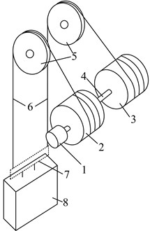
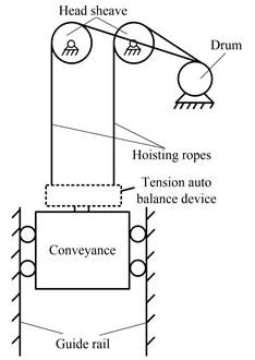
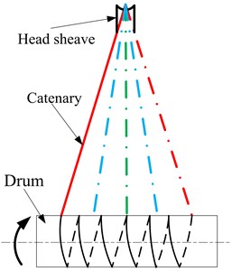
There are two types of vertical hoisting systems that are mainly used in coal mine hoists, single rope winding hoisting system and multi-rope friction hoisting system. For the single rope winding hoisting system, the weight of the hoisting rope increases quickly with the increase of the shaft depth, so that it acquires the diameter of the rope to be larger than 120 mm to realize the hoisting in shafts over 2000 m deep. Simultaneously, it also needs a larger drum with the length of over 8 m and with 4 to 6 winding layers, and this will cause a huge increase of running costs. For the multi-rope friction hoisting system, the indispensable balance ropes with time-varying length will result in time-varying loads in the hoisting ropes: While the conveyance reaches the head of the shaft, the hoisting ropes will bear the weight of the conveyance and all the balance ropes, however, the hoisting ropes will only bear the conveyance’s weight while the conveyance reaches the bottom of the shaft. The stress fluctuation of the hoisting ropes determines that only by lowering the lifting capacity could the system realize a deep hoist, and the deepest depth is about 1700 m. In order to realize a deeper hoist, the parallel hoisting system with tension auto balance device (TABD) attached to the ends of all the hoisting ropes, as shown in Fig. 1, is expected to be the first choice for the vertical shaft.
The vibrations of the hoisting ropes affect the stationarity of the conveyance [1-3] and threaten the conveyance safety [4-5], especially in mine hoists and elevator systems, thus, the dynamics of flexible hoisting system have been researched extensively. Roberts R. [6] and Watanabe S. [7] modeled the rope as divided mass and connecting springs with time-variant coefficients, but lots of unique dynamical properties of continuum can’t be revealed by this modeling method. Kaczmarczyk S. [3, 4] derived a distributed-parameter mathematical model of deep mine hoisting cables by employing classical moving co-ordinate frame approach and Hamilton’s principle, and the simulation results showed a vast range of potentially dangerous non-linear dynamic phenomena. Zhu W. D. [5] studied the stability of axially and vertically moving strings and beams with time variant length and complicated boundary conditions from the energy standpoint, and the exact expressions for the rates of change of energies of media are derived. An active control method to dissipate the vibratory energy was also discussed [6]. Because the allowable vibration in elevators is very small [1], Zhu W. D. [7] determined the lateral response of the hoisting rope with time-varying length and tension subjected to general initial conditions and external excitation, assuming that the lateral and longitudinal vibrations of elevator cables are uncoupled and the longitudinal vibration is negligible. The rate of change in the energy of the cable was also analyzed from the control volume and system viewpoints. Terumichi Y. [8] researched the nonstationary vibration of a string with a constant hoisting speed, and the analytical results showed that the axial velocity of the string influenced the peak amplitude of the string vibration at the passage through resonances. Bao J. H. [9] investigated the longitudinal vibration of the flexible hoisting system with time-varying length, and derived a Lyapunov controller which can dissipate the vibratory energy. Chi R. M. [10] discussed the relationship between the natural modes associated with homogeneous boundary conditions and the forced responses associated with inhomogeneous boundary conditions, and calculated the natural frequencies for the fixed end condition at the top end of the hoist rope. Zhang Y. H. [11] investigated the coupled vibration of a flexible cable transporter system with arbitrary varying length, the simulation results showed that the increase of the system damping dissipated the longitudinal vibration a lot, but had little influence on the lateral vibration. Since the governing equations of translating media with variant lengths are usually time-variant and nonselfadjoint, Zhu W. D. [12] and Ren H. [13] developed an accurate spatial discretization method to calculate the dynamic responses of one-dimensional distributed-parameter components with variant lengths and complicated matching conditions, and resolved several challenging problems in moving elevator cable-car systems. However, most of the studies of parallel ropes are confined to parallel manipulators [14-18], in which ropes are used to suspend end-effector and to adjust the end-effector pose, and ropes in these systems are usually modeled as rigid bodies or lumped mass. In Refs. [3, 4, 19], the multi-rope were simplified as one rope when establishing the mechanical model of the hoisting system, this simplification cannot be used to investigate the longitudinal vibration of the parallel ropes if the excitation of each rope is different from each other.
Fig. 1Schematic of parallel hoisting system with TABD
a)
b)
2. Mechanical model and governing equation
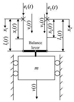
Ignoring the influences of the catenaries, the hoisting system can be simplified as two parallel strings with TABD attached to the ends of both ropes, and a mass attached to the end of the TABD. Several TABDs are applied in engineering applications following the same working principles. In this paper, the balance lever is selected to be the TABD so as to facilitate the establishment of the ADAMS simulation model. As shown in Fig. 2, the two hoisting ropes are connected to each side of the lever by hinge, and the conveyance is connected to the middle point of the lever also by hinge. The displacements of the upper ends of the two ropes, specified as and , where is time, the subscripts 1 and 2 refer to the rope 1 (the left rope) and the rope 2 (the right rope), respectively, represent the excitations that can arise from the eccentricity of each head sheave, respectively. and are the time-varying length of the two ropes, respectively, where is the prescribed displacement of the conveyance. and represent the hoisting velocity of each rope, respectively, and is the conveyance velocity.
Fig. 2Mechanical model of parallel ropes winding hoisting system
The relation between , and can be derived from Fig. 2 and can be expressed as:
Several assumptions were made to constrain the analysis:
1) The bending stiffness of the rope and all the system friction are ignored;
2) Only the longitudinal vibration is considered here;
3) The mass per unit length and longitudinal stiffness and of the ropes are constant.
Applying the Hamilton formulation to the model shown in Fig. 2 yields:
where and denote the system kinetic energy, the rope elastic strain energy and the gravitational potential energy, respectively. is the work done by the distributed damping forces. The kinetic energy of the system is:
where is the longitudinal displacement of the rope particle at position at time , and the operator is given by:
The elastic strain energy of the ropes is:
where and represent the strain measure in each rope, respectively. and represent the quasi-static tension in each rope, respectively. Since the rotations and displacements in the ropes are assumed to be small [4], and are given by:
and are given by:
When the gravitational potential energy in the initial equilibrium configuration is defined to be 0, the gravitational potential energy of the system is given by:
The work done by the distributed damping forces is:
the damping forces and are given by:
where is the damping coefficient of the two ropes, denotes partial differentiation with respect to .
Inserting Eqs. (3), (5), (8) and (9) into Eq. (2), using variational method and integrating by parts where necessary, yields the system of equations for the dynamic deflections as:
where the subscripts and denote partial differentiation, and are the instantaneous translational acceleration of each rope.
The associated boundary conditions are:
where is short for:
3. Spatial discretization
The derived governing equations are nonlinear partial differential equations (PDEs), and it is impossible to obtain an exact analytical solution. The Galerkin’s effort is applied here to truncate the infinite-dimensional Eq. (11) and (12) into a set of nonlinear finite-dimensional ordinary differential equations with time-variant coefficients. Using the transformations:
to transform the time-variant domain to a time-invariant domain [0, 1]. The new dependent variable can be expressed as:
and the partial derivatives of with respect to and are related to those of with respect to and :
Substituting Eqs. (14), (15) into Eq. (11), (12) yields:
The solution of Eqs. (16)-(17) are assumed in the form:
where and are the generalized coordinates, and are the trial functions, and is the number of included modes. The trial functions for the model in Fig. 2 are:
Substituting Eq. (18) into Eq. (16)-(17), multiplying the governing equation by , integrating it from to 1, and using the boundary conditions and the orthonormality relation for yields the discretized equations of longitudinal vibration for the parallel hoisting ropes:
where and are the vectors of generalized coordinates, and are symmetric mass matrices, and are symmetric damping matrices, and are symmetric stiffness matrices, and and are generalized force vectors. Entries of the system matrices and the force vectors are given in Appendix.
4. Application
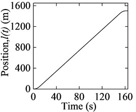
Numerical simulation tests are applied to evaluate the proposed mathematical models. The parameters for the hoisting system are 12.6 kg/m, 0.01, 66.5 t. The prescribed displacement, velocity, acceleration curves of the conveyance are shown in Fig. 3. The acceleration and maximum velocity are 1 m/s2 and 10 m/s respectively. The initial and maximum lengths of both ropes are 1 m and 1501 m respectively.
Fig. 3Movement curves of the conveyance
a)
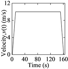
b)
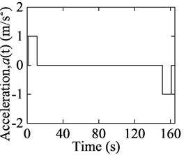
c)
4.1. Comparison between numerical solution and ADAMS simulation
MSC.ADAMS is a well-known multi-body simulation software package which is used to analyze the dynamical and kinematical properties of mechanical systems, and can also be used to verify the validity of theoretical solutions. On the basis of the concentrated-mass theory with multi-DOF, the two ropes are discretized into a certain amount of rigid cylinders, and each cylinder is set as 1 m long and 12.6 kg of weight. In order to simplify the simulation model, all of the cylinders of one rope are wound many coils around one head sheave in the same circle, as shown in Fig. 4. Aiming at reflecting the mechanical characteristics of the steel wire rope, the bushing force, a six-order diagonal matrix, is employed to connect two adjacent cylinders, and the first cylinder of each rope is connected to each side of the balance lever by revolute joint, as shown in Fig. 4. In order to minimize the lateral influence on the hoisting ropes when the balance lever rotates around its middle point, the length of the balance lever is set as 10 m. The conveyance is connected to the middle point of the balance lever by revolute joint, and a translational joint is created between the conveyance and the ground to constrain the transverse displacement of the conveyance. The weight of the conveyance is set as 66.5 t and the balance lever 1 kg.
Fig. 4ADAMS simulation model
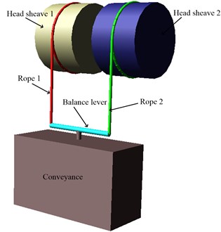
Fig. 5Schematic of the ADAMS driving strategy
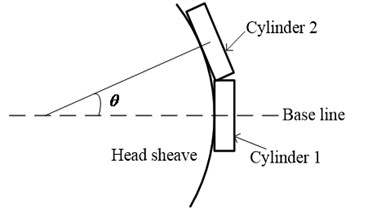
The ADAMS simulation is carried out using the driving strategy given by Wang J. J. [20], and the driving strategy can be summarized as follows. As shown in Fig. 5, each cylinder is connected to its head sheave by one fixed joint, and the wrap angle of each cylinder corresponding to the axis of the head sheave is . Then, the angle sensor corresponding to each fixed joint is created to detect the rotation angle of the head sheave. Driven by the rotational joint motion, each head sheave will rotate around its axis. When the rotation angle of the head sheave equals to (while the center of th cylinder reaches the base line which is defined initially), the ith sensor will be triggered and act to invalidate the th fixed joint, then the th cylinder will be separated from its head sheave which can achieve the hoisting cable reeled out.
The boundary excitations are given by and . The longitudinal response of the model in Fig. 2 is calculated with 10, and the comparisons between the ADAMS simulation and the numerical solution are shown in Fig. 6.
Fig. 6 has shown that the numerical solution inosculates well with the ADAMS simulation, which can verify the validity of the numerical solution. The small differences between the two results can be explained as follows: (i) Only longitudinal stiffness and axial damping are considered in the numerical solution, while the simulation is still affected by the bending stiffness, torsional stiffness, transverse damping and torsional damping. (ii) The transverse vibration affects the longitudinal vibration in the simulation. (iii) The simulation model is relatively simple.
Fig. 6Comparisons between ADAMS simulation and numerical solution
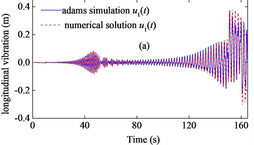
a) Comparison of rope 1
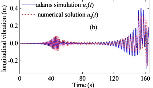
b) Comparison of rope 2
4.2. Discussion
The longitudinal vibration characteristics of the mechanical model shown in Fig. 2 are examined under different system coefficients, and the numerical results are shown in Figs. 7-10. Figs. 7-10 have displayed that the resonance phenomenon happened two times in both ropes. The reason can be explained as follows. For the parallel hoisting system with TABD attached to the ends of both rope, as shown in Fig. 2, the static longitudinal displacement of the conveyance can be expressed as:
Fig. 7Longitudinal responses of the hoisting ropes with e1t=0.01sinπt, e2t=0.01sin2πt and EA1=EA2= 4.894×10⁸ N
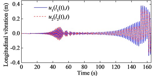
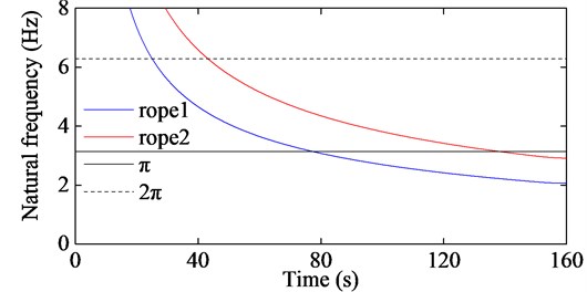
Since the conveyance is suspended by both ropes, the last two terms of Eq. (21), , will consequently be another excitation which will affect the longitudinal responses of both ropes. That is to say, if the natural frequency of one rope closes to the frequency of or , that rope will resonate.
Fig. 8The first order natural frequencies of the two hoisting ropes corresponding to Fig. 7
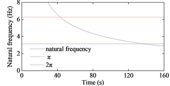
Fig. 9Longitudinal responses of the hoisting ropes with e1t=0.01sinπt, e2t=0.01sin2πt, EA1= 2.447×10⁸ N and EA2= 4.894×10⁸ N
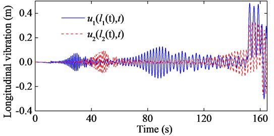
Fig. 10The first order natural frequencies of the two hoisting ropes corresponding to Fig. 9
It is certain that the excitation at the upper end of rope 1 will cause vibration in rope 1. This vibration will be superposed onto the vibration caused by the conveyance after being dissipated by the system damping. Similarly, the dynamical displacement at the lower end of rope 2 is also a result of superposition of two vibrations caused by the conveyance and , respectively. This can explain that when the longitudinal stiffness of the two ropes are the same, the dynamical displacement of rope 2 is larger than that of rope 1 when the natural frequency of the rope closes to the frequency of , and the dynamical displacement of rope 1 is larger than that of rope 2 when the natural frequency of the rope closes to the frequency of , as shown in Fig. 7.
Moreover, all the longitudinal vibration curves have shown that the acceleration affects the longitudinal response a lot, especially when the rope is relatively long.
4.3. Control strategy
As performed in [9], a Lyapunov controller which controls the output of driven motor can dissipate the longitudinal vibratory energy very well. For the hoisting system shown in Fig. 1, there are two main factors that cause system vibration: the movement profile curves (namely the acceleration/deceleration) and the external excitations. The vibration caused by the former factor is inevitable due to the change of time-varying dynamic parameters such as rope length, hoisting velocity, acceleration etc. The latter factor includes three main sources: the outline of head sheave, the eccentricity of head sheave and the interference generated by the varying length of catenary, as shown in Fig. 11. For the parallel hoisting system, whose two hoisting ropes are driven by one motor, the external excitation of each rope will be different considering the superposition of the three sources, and it is infeasible to dissipate the vibration by controlling the output of motor. Thus, it will be a promising way to solve the vibration problem by controlling the movement of each head sheave.
Fig. 11External excitations
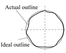
a) Outline of head sheave
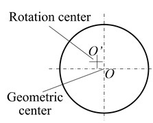
b) Eccentricity of head sheave
c) Interference model of motion
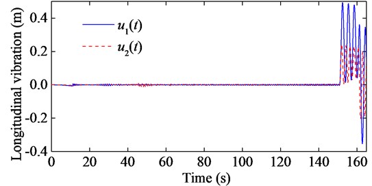
As shown in Fig. 12, each head sheave is installed on a displacement actuator, which is fixed on the head frame, and can move vertically driven by the actuator. If the movement of each head sheave, expressed as and respectively, satisfies and , then the rope will vibrate only due to the acceleration/ deceleration, and no resonance will happen. If and satisfy , then the excitation from the conveyance vanishes. Though each excitation at the upper end of each rope will still affect the corresponding rope, they will affect little on the lower ends of both ropes due to the effect of damping, as shown in Figs. 13-14.
Fig. 12Schematic of control strategy
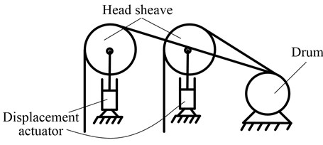
Fig. 13Longitudinal responses of the hoisting ropes with e1t=0.01sin2πt+π, e2t=0.01sin2πt and EA1=EA2= 4.894×10⁸ N
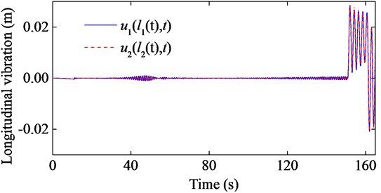
Fig. 14Longitudinal responses of the hoisting ropes with e1t=0.01sin2πt+π, e2t=0.01sin2πt, EA1= 2.447×10⁸ N and EA2= 4.894×10⁸ N
5. Conclusions
1) The mechanical model of the parallel hoisting system with TABD attached to each of the rope has been established after several simplifications. Consequently, the governing equations of the longitudinal response of parallel hoisting system have been derived based on Hamilton’s principle.
2) An ADAMS simulation of the parallel hoisting system has been established based on the theory of multi-DOF, and the simulation results have verified the validity of the numerical solution.
3) For the parallel hoisting system with TABD attached to the ends of all ropes, the vibration of each rope is a superposition of two vibrations caused by the excitations from the conveyance and the upper end of the rope, respectively. Due to the effect of damping, the excitation from the conveyance will be the key factor that causes the vibration at the lower ends of both ropes. System acceleration will also cause relatively large vibrations in the ropes.
4) When the movement of each displacement actuator is properly designed, the proposed control strategy can dissipate the vibration of parallel hoisting system greatly. This offers an opportunity to stabilize the hoisting system through design of specific displacement actuator movement curve, which is a key issue in the future research.
References
-
Zhu W. D., Ni J. Energetics and stability of translating media with an arbitrarily varying length. Journal of Vibration and Acoustics, Vol. 122, Issue 3, 2000, p. 295-304.
-
Zhu W. D., Ni J., Huang J. Active control of translating media with arbitrarily varying length. Journal of Vibration and Acoustics, Vol. 121, Issue 3, 2001, p. 347-358.
-
Zhu W. D., Chen Y. Forced response of translating media with variable length and tension: Application to high-speed elevators. Proceedings of the Institution of Mechanical Engineers, Part K: Journal of Multi-body Dynamics, Vol. 219, Issue 1, 2005, p. 35-53.
-
Kaczmarczyk S., Ostachowicz W. Transient vibration phenomena in deep mine hoisting cables. Part 1: Mathematical model. Journal of Sound and Vibration, Vol. 262, Issue 2, 2003, p. 219-244.
-
Kaczmarczyk S., Ostachowicz W. Transient vibration phenomena in deep mine hoisting cables. Part 2: Numerical simulation of the dynamic response. Journal of Sound and Vibration, Vol. 262, Issue 2, p. 245-289.
-
Roberts R. Control of high-rise/high-speed elevators. Proceedings of IEEE American Control Conference, Vol. 6, 1998, p. 3440-3444.
-
Watanabe S., Okawa T., Nakazawa D., Fukui D. Vertical vibration analysis for elevator compensating sheave. Journal of Physics: Conference Series, Vol. 448, Issue 1, 2013, p. 012007.
-
Terumichi Y., Ohtsuka M., Yoshizawa M., Fukawa Y., Tsujioka Y. Nonstationary vibrations of a string with time-varying length and a mass-spring system attached at the lower end. Nonlinear Dynamics, Vol. 12, Issue 1, 1997, p. 39-55.
-
Bao J. H., Zhang P., Zhu C. M. Modeling and control of longitudinal vibration on flexible hoisting systems with time-varying length. International Conference on Advanced in Control Engineering and Information Science, Yunnam, China, 2011, p. 4521-4526.
-
Chi R. M., Shu H. T. Longitudinal vibration of a hoist rope coupled with the vertical vibration of an elevator car. Journal of Sound and Vibration, Vol. 148, Issue 1, 1991, p. 154-159.
-
Zhang Y. H., Agrawal S. Coupled vibrations of a varying length flexible cable transporter system with arbitrary axial velocity. Proceedings of the American Control Conference (AAC), Boston, 2004, p. 5455-5460.
-
Zhu W. D., Ren H. An accurate spatial discretization and substructure method with application to moving elevator cable-car systems-part I: Methodology. Journal of Vibration and Acoustics, Vol. 135, Issue 5, 2013, p. 051036.
-
Ren H., Zhu W. D. An accurate spatial discretization and substructure method with application to moving elevator cable-car systems-part II: Application. Journal of Vibration and Acoustics, Vol. 135, Issue 5, 2013, p. 051037.
-
Korayem M. H., Bamdad M. Dynamic load-carrying capacity of cable-suspended parallel manipulators. International Journal of Advanced Manufacturing Technology, Vol. 44, 2009, p. 829-840.
-
Korayem M. H., Tourajizadeh H., Bamdad M. Dynamic load carrying capacity of flexible cable suspended robot: Robust feedback linearization control approach. Journal of Intelligent and Robotic Systems: Theory and Applications, Vol. 60, Issue 3-4, 2010, p. 341-363.
-
Korayem M. H., Bamdad M., Tourajizadeh H., Korayem A. H., Bayat S. Analytical design of optimal trajectory with dynamic load-carrying capacity for cable-suspended manipulator. International Journal of Advanced Manufacturing Technology, Vol. 60, Issue 1-4, 2012, p. 317-327.
-
Lee T. Y., Shim J. K. Improved dialytic elimination algorithm for the forward kinematics of the general Stewart-Gough platform. Mechanism and Machine Theory, Vol. 38, Issue 6, 2003, p. 563-577.
-
Oftadeh R., Aref M. M., Taghirad H. D. Forward kinematic analysis of a planar cable driven redundant parallel manipulator using force sensors. 23rd IEEE/RSJ International Conference on Intelligent Robots and Systems, Taipei, 2010, p. 2295-2300.
-
Xiao X. M., Wu J., Ma C. Dynamic analysis and simulation on sliding process of multi-rope friction hoist. International Conference on Mechanic Automation and Control Engineering, Wuhan, 2010, p. 220-223.
-
Wang J. J., Cao Guohua, Wang Y. D., Wu R. H. A novel driving strategy for dynamic simulation of hoisting rope with time-varying length. International Journal of Modeling, Simulation, and Scientific Computing, Vol. 4, Issue 3, 2013, p. 1350009.
About this article

This work is supported by the National Natural Science Foundation of China (51475456), the Fundamental Research Funds for the Central Universities (2014YC06), the National Key Basic Research Program of China (2014CB049404), and the Project Funded by the Priority Academic Program Development of Jiangsu Higher Education Institutions (PAPD).
