Abstract
In this paper, the nonlinear vibration characteristics of spur gear-rotor system and the interactions among of gear shaft, and bearing with backlash subjected to internal/external excitation are systematically investigated. The two-degree-of-freedom purely torsional generalized lumped parameter model of the spur gear system with meshing stiffness, backlash, transmission error and external periodic excitation is established. The Newmark method is used to solve simultaneously the differential equations for analysis the vibration response characteristics as well as the effects of rotational speed, backlash and mesh damping coefficient on the dynamic characteristics of the spur gear system. The numerical results clearly reveal that the system exhibits an increase mesh damping coefficient and a decrease backlash can reduce the degree of gear nonlinearity effect, which makes the meshing state of spur gear system change from double-sided impact, single-sided impact to no impact. In addition, the rotational speed has a significant effect upon the dynamic response of the system, which shows that designing a gear system to operate at a high rotational speed should be avoided especially when the rotational speed is close to the system’s natural frequency and half of the natural frequency. The results presented in this study provide an understanding of the operating conditions under which undesirable dynamic motion takes place in a spur gear system and therefore serve as a useful source of reference for engineers in designing and controlling such systems.
1. Introduction
Gear transmission systems are one of the most important transmission forms in the machinery industry, which are widely used in wind turbine, automotive, aviation, marine and other drive industries. The compact structure, high transmission efficiency and strong load capacity are closely related to all aspects of the economic and social life. However, due to the time-varying mesh stiffness, the different support types and looseness caused by backlash [1], manufacturing/assembly error and elastic deformation of the meshing gears, instability, the vibration and noise are generated particularly during the approach and recess of the tooth meshing. In addition, the mesh impact is also presented when the gear drive is under the conditions of the sudden loading and change of speed. These nonlinear factors have a detrimental effect on dynamic characteristics of a gear system. Therefore, in order to achieve improved dynamic characteristics of gear drives and enhanced load carrying capacity and reliability, it is very important to establish exact dynamics model and to analyze lateral-torsional coupling vibration of a geared rotor system. The aims of these models vary from noise control to stability analysis and range from a single-degree of freedom to strong nonlinear multi-degree of freedom models. The proposed models differ from each other mainly in degrees of freedom, elements considered in the model, the solution technique used, the type of response calculated, type of excitation etc. [2]. In recent years, with the increased demand for high speed and heavy load machinery, the mathematical modeling and nonlinear dynamic characteristics of gear system gained importance. Many researchers have made a great contribution to dynamic behaviors of gear systems by respectively applying experimental methods, numerical simulation technique and analytical methods [3-5]. Because of the influence of the gear and bearing couplings, the gear system can use of either single-DOF model or multi-DOF models considering the time-varying parameters and other nonlinear effects in the model, which makes it possible to analyze influences of the key parameters in gear system. Cai [6] developed 2-DOF linearized model of one tooth pair including the time-varying meshing stiffness and transmission error and achieved a good agreement of calculated and measured vibration of two pairs of test gears. A. Kaharman and R. Singh [7] studied the nonlinear dynamic characteristics of spur gear system with the harmonic balance method. In order to further study the nonlinear characteristics of gear transmission system, A. Kaharman [8] deduced the nonlinear dynamic equation of spur gear rotor system and the influences of various parameters were studied, which solved the nonlinear dynamic response of spur gear system with HBM and Runge-Kutta. Due to the effect of time-varying mesh stiffness, A. Kaharman [9-10] sequentially analyzed the effect of the gear rotor-bearing system with the backlash and the time-varying meshing stiffness, and carried on a detailed analysis to the nonlinear system. Padmanabhan [11] utilized a parametric continuation technique to model a periodically excited nonlinear gear system and showed that the system exhibited high-order sub-harmonic responses under particular operating conditions. Zhu [12] studied a nonlinear coupling dynamic system with multi-speed gear-driven, which includes the gears transmission shafts and gearbox, and the dynamic characteristics of the coupling system were analyzed by considering the internal excitation to the system. Shen [13] utilized the incremental harmonic balance method to analysis a single degree-of-freedom dynamic model for a spur gear pair considering the time-varying stiffness, the backlash and a static transmission error, and then demonstrated the effectiveness of increasing the damping coefficient ratio or excitation amplitude as a means of controlling the dynamics of the system. Chang and Chen [14-18] presented a series of investigations into the dynamic behavior of a gear-bearing system with nonlinear suspension, nonlinear oil-film force, and nonlinear gear mesh force. The results provide an understanding of the operating conditions under which undesirable dynamic motion takes place in a gear-bearing system. Byrtus [19] studied the qualitative analysis of large rotational systems with gear and bearing couplings and the influence on the dynamic system response to the internal kinematic excitation in gearing and to parametric excitation caused by the time-varying meshing stiffness. Aiming at gear transmission system’s complex nonlinear dynamic problems including dynamic transmission error, single-sided impact and double-sided impact, separation, rattling and chaos. Ma [20] and Zhang [21-22] presented a dynamic model of a multi-shaft helical geared rotor system with geometric eccentricity, gear mesh and bearing flexibility. Yang [23] investigated the vibration characteristics of a gear train with multi-meshes under both deterministic and random loads. The equation of motion is solved with stochastic Newmark algorithm and the responses of the displacements, including means and standard deviations, are obtained through numerical integration. Palermo [24] presented a contact element for global dynamic simulations of gear assemblies using multi-body modeling that enables to take into account real-case parameters in a scalable way. Zhang [25] studied the dynamics of a spur gear meshing and coupling system, and utilized the multiple scale method to analyze the parametric instability under main and sub-harmonic resonant conditions. Liang [26] presented the dynamic analysis method based on perfectly elastic body, and established a 3-D dynamic contact nonlinear model of housing-bearing-helical gear pair system. The dynamics characteristics on the key components were obtained by dynamically simulating the system.
Accurate analytical modeling, including proper gear mesh relations and detailed characterization of the nonlinear dynamics of spur gear, is needed to estimate relative gear vibration and predict dynamic forces in industrial applications. It can be seen that though much work has been devoted to nonlinear dynamic of gear systems, the nonlinear dynamic analysis of spur gear pair systems coupling with bearing were not found in previous researches. Furthermore, it is noteworthy that earlier studies are mainly concentrated on the nonlinear dynamic characteristics of gear systems under internal or external excitations respectively. As we all know, the dynamic excitations in practical gear systems are composed of internal and external excitations. The nonlinear dynamic characteristics of gear pair system under combined internal and external periodic excitations have been scarcely studied. Most of the spur models are simplified single-DOF models, which are slightly inappropriate for high rotational speed spur gear system, and its application during the design and analysis stage may result in a flawed or potentially dangerous operation.
The organization of this paper is as follows. In the next section, a gear-pair model is developed, involving two torsional degrees of freedom and the motion is deduced. In addition to the non-linearities due to the bearing and the gear meshing forces, and the gear static transmission error and the backlash appear as non-linear terms in the equations of motion. In section 3, the numerical analysis results are presented for the dynamic analysis of geared rotor-bearing models. Nonlinear dynamic behaviors of the system by discussing the influence of the rotational speed, backlash and mesh damping coefficient parameters on the periodic motions are illustrated by a series of response diagrams. Finally, section 4 presents some brief conclusions.
2. Dynamic model and equations of motion
2.1. Lumped-parameter analytical model
The simplified two-degree-of-freedom purely torsional generalized lumped parameter model to investigate the spur gear-bearing system under the external and internal excitations effect and strongly nonlinear backlash effect is established in Fig. 1. Fig. 1(a) presents a schematic illustration of the dynamic model considered between driving gear and driven gear. Fig. 1(b) shows a simple mechanical model, retaining the essential characteristics which arise from the interaction of spur gear mesh and the bearing nonlinearities.
Fig. 1Two degrees of freedom nonlinear model of the spur gear pair system
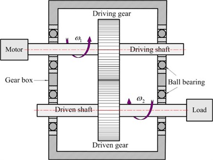
a) Schematic illustration of the gear-bearing system
b) Dynamic model of the gear-bearing system
In this study, the two gears with the same base radius are selected, i.e. driving and driven gears have the same geometric parameters. In addition, some assumptions are presented to simplify dynamic model: (a) Friction forces at the gear mesh point are neglected; (b) The bearings and shafts that support the gears are modeled by equivalent elements with viscous damping coefficient ( 1, 2) and linear spring ( 1, 2); (c) The mesh stiffness and damping values are denoted by and , which are applied at respective gear meshes in the direction of the gear mesh line of action. The high-frequency internal excitation of the static transmission error is considered in the formulation, and the input torque and output torque are assumed to be low-frequency, namely and .
In Fig. 1(a), each gear of polar mass moment of inertia (1, 2) and base radius is allowed to vibration in torsional direction by . and are the center of driving and driven gears. The torsional angular displacement of gear is assumed to result from a constant angular velocity term plus a small torsional vibration angular displacement due to vibrations originating from the flexibility of the meshing gear teeth. Therefore, the angle displacements of the driving and driven gears can be expressed by the following equations:
where and are the constant angular velocity components of the driving and driven gears.
2.2. Differential equations of motion
According to the previous geometrical relationships, as shown in Fig. 1, a displacement vector of a spur gear pair can be defined from the pressure line co-ordinate system. So the generalized co-ordinates vector of the nonlinear dynamic model including 2 degrees of freedom can be defined as follows:
From the proposed concept, taking into the meshing stiffness, backlash, and transmission error as well as torque fluctuation. In addition, the displacement force relation at the bearings is taken as linear in this paper. The kinetic energy , the potential energy and the dissipation function are established. Utilizing the Lagrange equation, then equations of the two-degree-of-freedom torsional motion of the nonlinear geared system, as shown in Fig. 1, can be expressed as:
where, the dot on each variable means derivative with respect to time ; the number of overdots represents the order of differentiation with respect to time ; ( 1, 2) is the torsional displacement of the driving/driven gear; is the dynamic meshing force of the gear acting on the meshing points, which can be written as:
where, is the actual transmission error, which represents geometrical errors of the teeth profile and spacing. is gear static transmission error, which is supposed fits monogenetic harmonic function. Therefore they can be as followings:
where, and stand for the mean and fluctuation; is the gear meshing frequency, and , is the initial phase of transmission error; and are rotational speed of gears; Integer and represent the teeth number of driving and driven gears.
And is a non-analytical function essentially describing the nonlinear elastic restoring force of gear pair. It can be defined as:
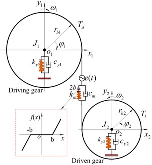
The backlash nonlinearity function that simulates clearances and illustration of impact are shown in Fig. 2. According to the backlash nonlinearity function [27], the impact is not observed in a gear system if the displacement lies in the region and . This condition is shown in Fig. 2 as case I. Double-sided impact case exists if the displacement lies in the region and and illustration of double-sided impact case II is shown in Fig. 2. When the displacement lies in the region and or and , the system presents single-sided impact case III. In this paper, when the system exists the impacts, which include the double-sided impact and single-side impact, the system presents a unstable motion state, otherwise the system lies in a stable sate.
Fig. 2Nonlinear displacement function
Substituting Eqs. (4)-(7) into Eq. (3), the nonlinear differential dynamic equation of spur gear pair system can be expressed as follow:
For analytical convenience, the Eq. (8) can be expressed in matrix equation, which can be transferred to the following expression:
where, and is the mesh damping coefficient.
3. Numerical simulation and discussion
Table 1System parameters of gear transmission
Case study | Driving/driven gear | Case study | Driving/driven gear |
Number of teeth | 20 | Meshing stiffness | 5.0×10⁸ N/m |
Module | 10 mm | Meshing damping | 8.0×10² N/(m/s) |
Moment of inertia | 0.05 kg.m2 | Error mean | 2.0×10⁻⁵ m |
Radius | 0.1 m | Error fluctuation | 3.0×10⁻⁵ m |
Torsional stiffness | 4.0×10⁶ N.m/rad | Torque mean | 100 N/m |
Torsional damping | 5.0×10² N/(rad/s) | Torque fluctuation | 300 N/m |
Through a previous analyzing, it can be seen that the spur gear pair is a complicated system with the strong nonlinearity, time variance and complicated working environment. Therefore, it is necessary to give a detailed analysis of the gear system. To investigate the spur gear dynamic characteristics based on the above analysis, the following sections involves the discussion about the consequence the changing of the parameters, which are listed in Table 1. Substituting these parameters into Eq. (10), the nonlinear dynamic equations for the gear-bearing system with nonlinear backlash and static transmission error effects were solved using the New-Mark method. Let rotational speed , backlash and mesh damping coefficient be control parameters in the following analysis. In order to obtain a basic understanding of the spur gear dynamic behavior, the nonlinear vibration behavior of the gear system is characterized by using time process diagram, frequency spectrum, phase diagram and actual transmission error.
3.1. Effect of the rotational speed on dynamic response
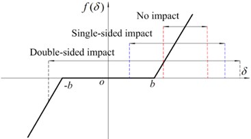
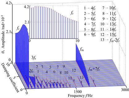
The piecewise nonlinear systems with periodically parameters have attracted significant attention. In practical gear rotor system, the rotational speed is commonly used as a control parameter. Accordingly, this section devotes itself to studying the effect of the rotational speed on the dynamic responses with the two-degree of freedom gear pairs system, and only the stable solutions are shown here. Because the vibration of the driving/driven gear exhibits the similar form of motions, driving gear vibration is taken for example. Keeping all other parameters unchanged, Fig. 3 presents the 3-D frequency spectrum diagram for the torsional vibration of driving gear using the frequency parameter as 3-D frequency spectrum parameter. The frequency amplitude shows significantly different nonlinear characteristics when is increased from 100 rad/s to 4000 rad/s. It can be observed from Fig. 3 that the nonlinear dynamic characteristics such as parametric resonance (primary resonance and sub-harmonic resonance) and jump phenomena are strongly attributed to the internal/external excitation. Namely, at low values of the rotational speed (300 rad/s), the frequency amplitude reduces gradually. However, the super-harmonic resonances can be found as is increased from 300 rad/s to 800 rad/s, the frequency amplitude reaches to a response peak at 800 rad/s. Due to the influence of backlash, transmission error and internal/external excitation, The peak value of the sub-harmonic resonance and the corresponding resonance frequency show to move forward, which is similar to a slightly hardening spring case at sub-harmonic resonance position and the multivalued transition frequency region becomes narrower. As the control parameter is further increased, the 3-D frequency spectrum contains a response peak at 2600 rad/s in addition to a response peak at 800 rad/s. The peak value and the corresponding resonance frequency of the primary resonance seem to move backward appreciable, which shows the hardening spring case. Finally, with the increase of control parameter ( 2600 rad/s), the frequency amplitude exists obviously jump discontinuity behavior, and decreases significantly. The 3-D frequency spectrum only contains 1-rotational frequency and meshing frequency components, and 1-rotational frequency is the dominant.
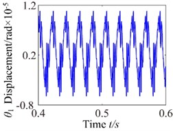
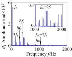
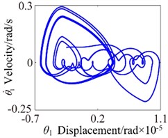
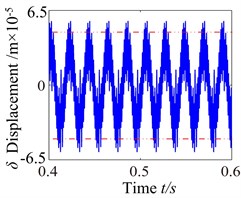
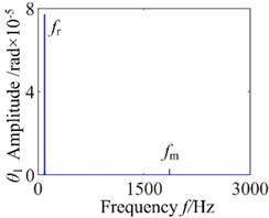
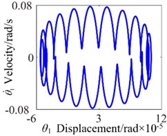
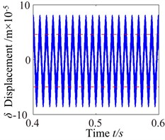
For a better clarity, Figs. 4-7 show the comparison of the calculated speed factors of four different values of 300 rad/s, 800 rad/s, 2600 rad/s and 360 rad/s, respectively. It can be seen from Figs. 4-7 that the responses of gear pair system show the different vibration characteristics with the increase of rotational speed. In these four cases, the torsional vibration angular displacement decreases first, increases and then decreases. Frequency spectrograms reveal numerous excitation frequencies. Phase diagram shows disordered dynamic behaviors. When 300 rad/s, the 1-rotational frequency () is the dominant response, the meshing frequency () amplitude is relatively small. In addition, the frequency spectrum also shows a number of different amplitude discrete frequency components, which are distributed ( is a positive integer), the phase diagram gradually translates into a irregular pattern. Taking off a tooth phenomenon is one of the major reasons in the meshing process, which makes spur gear pair show a different meshing impacts state and the phenomenon can be proved in Fig. 4(d). It can be seen from Fig. 4(d) that actual transmission error lies in the region ( 5.0×10⁻⁵ mm) and and the double-sided impact is observed in a geared system. The system lies in an unstable stable.
Fig. 33-D frequency spectrum using as ω control parameter
Fig. 4ω= 300: a) time process diagram, b) frequency spectrum, c) phase diagram, d) actual transmission error
a)
b)
c)
d)
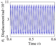
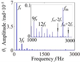
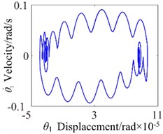
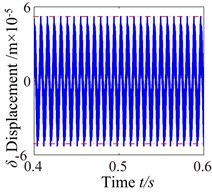
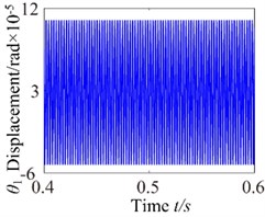
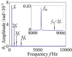
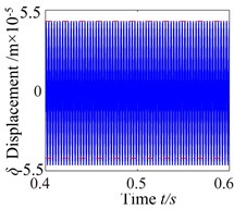
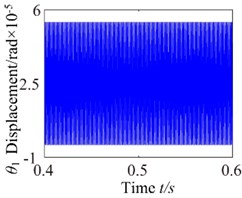
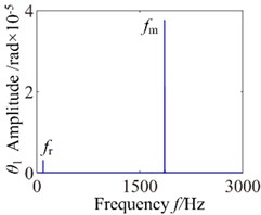
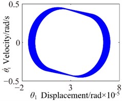
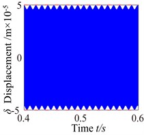
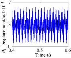
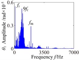
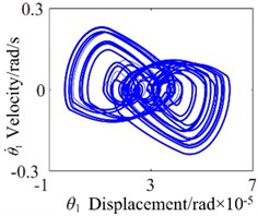
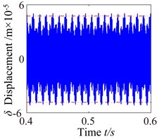
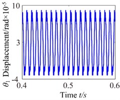
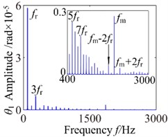
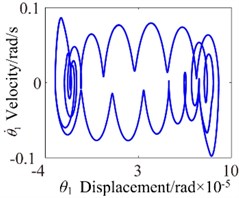
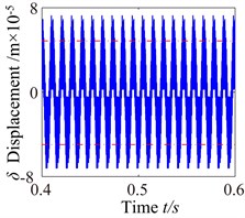
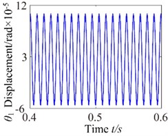
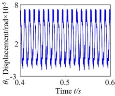
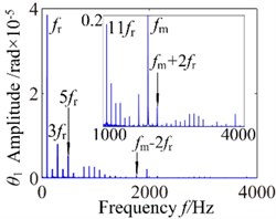
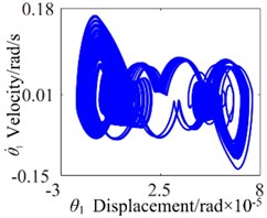
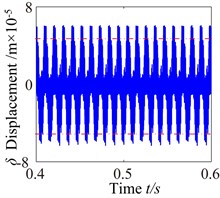
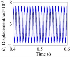
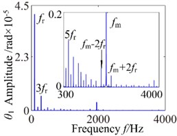
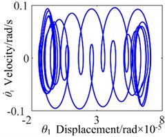
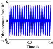
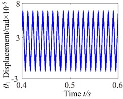
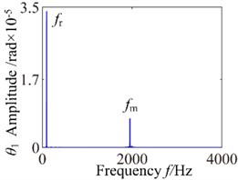
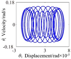
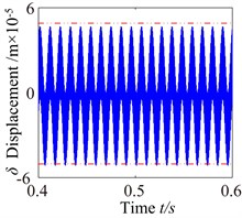
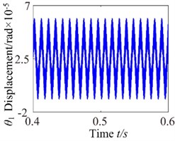
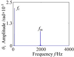
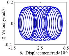
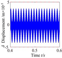
When 800 rad/s, the system appears sub-harmonic resonance phenomenon. As can be seen from the time process diagram that the torsional vibration angular displacement considerably increases. 1-rotational frequency reaches to sub resonance vibration peak, meshing frequency reduces slightly and the odd frequency components appear in frequency domain. In addition, phase diagram became more regular and the system lies in the critical state of double-sided impact and single-sided impact but the single-sided impact dominant. The system presents an unstable stable. When 2600 rad/s, the vibration waveform has obviously change where harmonic components decrease but the vibration amplitude in rotational direction increases significantly. The frequency components (, , ) are clearly presented on the frequency spectrum, and other harmonics of order 2, 4, 5 and so on withdraw gradually. However, it can be found by observing, phase diagram represents obvious vibration regularity, and the stabilized orbit slightly exhibits 20 (number of teeth) oscillations associated with the gear mesh period. The system generally tends to be stable. As the increase of rotational speed, the system translates into no impact state. When 3600 rad/s, torsional vibration angular displacement reduces evidently and harmonic components is relatively small, which consistently matches with changing trend of 3-D frequency spectrum diagram. In the frequency domain, 1-rotational frequency () is the dominant response and the amplitude of meshing frequency () is obvious.
Fig. 5ω= 800: a) time process diagram, b) frequency spectrum, c) phase diagram, d) actual transmission error
a)
b)
c)
d)
Fig. 6ω= 2600: a) time process diagram, b) frequency spectrum, c) phase diagram, d) actual transmission error
a)
b)

c)
d)
However, the phase diagram obviously exhibits 20 oscillations, which shows that the system presents a stable motion state. In a word, the input rotational speed also governs the vibration frequency of the input/output torque and meshing force. When the rotational speed is low, the phase diagram shows that a region is completely filled by the phase trajectory. The vibration rules of the phase diagram become obviously with the increasing rotational speed, and no significant impact behavior is observed. Moreover the size and vibration of the steady-state phase diagram of the spur gear depends on the torques and meshing force, on the meshing force and on the dynamic loading which in turn depend in a nonlinear way on the rotational speed. In addition, all the phase diagram orbits have the different sizes and coordinates. The orbits of the elliptical motion increase firstly then decrease with the changing rotational speed, which indicates that the rotational speed has a major influence.
Fig. 7ω= 3600: a) time process diagram, b) frequency spectrum, c) phase diagram, d) actual transmission error
a)

b)
c)
d)
3.2. Effect of the backlash on dynamic response
Non-backlash is usually adopted in gear design, while backlash always exits and is generally shown as non-linearity in consideration of manufacture error, installation error, and hot deformation and so on. Therefore, the backlash has an import influence on gear dynamics and it has a strong non-linear characteristic, which makes the meshing contact state of spur gear change inevitability. Sometimes the system lies in a double-sided impact, single-sided impact, and alternates between double-sided impact and single-sided impact. The alternating of the impact doesn’t show the specific rule at action time and peak load, which causes strong vibration and higher impact load, and then have a great influence on reliability and life-span of the gear system. Thereby the effect on gear dynamics by the gear backlash is very complex. In order to get reasonable and precise dynamic analytic result, keeping all other parameters unchanged, and the dynamic behaviors are analyzed at operating speed ( 600 rad/s). Fig. 8 presents the 3-D frequency spectrum diagram for the torsional vibration angular displacement of driving gear using the backlash as 3-D frequency spectrum parameter. It can be observed that the 3-D frequency spectrum exhibits different changing tendency along with different backlash. At low values of the backlash, i.e. 3.2×10⁻⁵ mm, the meshing frequency () is the dominant response and the amplitude of 1-rotional frequency () is relatively small. The meshing frequency component reduces and 1-rotional frequency increases gradually with the increasing of the backlash. As the backlash is further increased from 3.2×10⁻⁵ mm to 8.8×10⁻⁵ mm, 1-rotational frequency of the gear increase gradually, and the meshing frequency component decreases slightly. The 1-rotational frequency is the dominant response in the frequency domain. In addition, other rotational frequency components reduce gradually under certain backlash condition. At higher values of the backlash, i.e. 8.8×10⁻⁵ mm, 1-rotational frequency and meshing frequency components remain about the same and the 1-rotational frequency is still dominant. Other rotational frequency components withdraw obviously. The reason is that the gear is taking off a teeth state basically, when the backlash increases to more than a critical value. In addition, it is noted that the amplitude of the rotational frequency () is lesser, but the amplitude of the meshing frequency () is greater at low values of the backlash. With the increasing of backlash , the increases gradually, and the decrease. It can be found that the amplitude reaches to the minimum at 3.2×10⁻⁵. Therefore, the minimization of backlash is 3.2×10⁻⁵.
Fig. 83-D frequency spectrum using as b control parameter
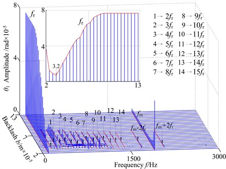
Fig. 9b= 2.0×10⁻⁵: a) time process diagram, b) frequency spectrum, c) phase diagram, d) actual transmission error
a)
b)
c)
d)
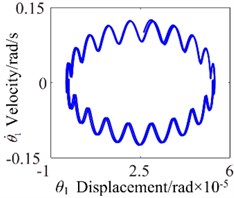
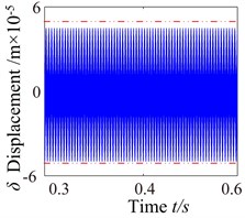
To detailedly investigate the effects of the backlash on nonlinear response, four backlash conditions chosen as follow: 2.0×10⁻⁵ mm, 3.2×10⁻⁵ mm, 6.4×10⁻⁵ mm and 8.8×10⁻⁵ mm. The time process diagram, phase diagram, frequency spectrum and actual transmission error are exemplified to describe corresponding dynamic responses in Fig. 9-12. When 2.0×10⁻⁵ mm, it can be seen from Fig. 9 that the harmonic component of the system is simple, which mainly contains meshing frequency (20) and 1-rotational frequency and the meshing frequency () is the dominant component. In addition, the phase diagram orbit shows approximate elliptic motion and no significant impact behavior is observed.
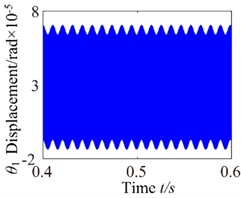
In this case, the overall frequency response appears approximate linear and the motion of the spur gear system presents a steady state. For 3.2×10⁻⁵ mm case, the amplitude of torsional vibration slightly decrease but the frequency spectrum and phase diagram appear more complex harmonic characteristics, which can be observed as shown in Fig. 10. The response of the system has the very complicated multiple harmonic components, which shows a continuous spectrum phenomena. The 1-rotational frequency (95.5 Hz) is the dominant frequency component and 9-rotational frequency (859.5 Hz) is second only to the 1-rotational frequency. Phase diagram is relatively clutter and the super gear shows single-side and no impact occur, the single-side impact is the dominant. The system presents unstable motion state gradually. Due to the effect of the backlash, the oscillation of multiple frequency components are found mutual coupling because there is no common factors found in the combined frequencies, which make them irreducible. Therefore the dynamic performance of the gear system deteriorates progressively. When backlash is increased further to 6.4×10⁻⁵ mm, the amplitude of torsional vibration is increased slightly.
Fig. 10b= 3.2×10⁻⁵: a) time process diagram, b) frequency spectrum, c) phase diagram, d) actual transmission error
a)
b)
c)
d)
Fig. 11b= 6.4×10⁻⁵: a) time process diagram, b) frequency spectrum, c) phase diagram, d) actual transmission error
a)
b)
c)
d)
It also clearly sees the presence of several peaks in frequency spectrum. These peaks correspond to the 1-rotational frequency 95.5 Hz), 3-rotational frequency (286.5 Hz) and mesh frequency (1909.9 Hz) and a number of different amplitude discrete frequency components, distributing . However, can be found by observing, phase diagram appears shows its own regular vibration pattern. The stabilized orbit of the phase diagram slightly exhibits 20 (number of teeth) oscillations associated with the gear mesh period, and the size of phase diagram decreases obviously. There are two types of impacts case: singles-side impact and double-side impact dominating the response. At 8.8×10⁻⁵ mm, the response amplitude increases considerable but the frequency components are characterized by an decrease of the picks corresponding to the eigenfrequencies of the system, which shows only the 1-rotational frequency (95.5 Hz) and meshing frequency (20). The 1-rotational frequency is far greater than the meshing frequency and the 1-rotational frequency is dominant component. In phase diagram, it obviously exhibits 20 oscillations. Moreover, wider range of impacts appears and the response becomes more unpredictable, the system presents unstable motion state.
Fig. 12b= 8.8×10⁻⁵: a) time process diagram, b) frequency spectrum, c) phase diagram, d) actual transmission error
a)
b)
c)
d)
3.3. Effect of the mesh damping coefficient on dynamic response
Mesh damping coefficient is another important parameter that affects the dynamic response substantially, and because the gear pair always lies in meshing into/out of the state, the mesh damping coefficient has a significant effect on the impact of the gear pair. In order to investigate the effects and get precise dynamic analytic result, keeping all other parameters unchanged, Fig. 13 presents the 3-D frequency spectrum diagram for the torsional angular vibration of driving gear using the mesh damping coefficient as 3-D frequency spectrum parameter. As expected, the results show that the frequency response amplitude increases and decreases as is increased. At low values of the mesh damping coefficient case where 2.0, it can be seen the rich frequency components including 1-rotational frequency (), 2-rotational frequency (), multi-rotational frequency (), meshing frequency () and coupling frequency components (, …), where the 1-rotational frequency is the dominant response. In addition, 1-rotational frequency shows the change trend of increase gradually. As 2.0, 1-rotational frequency amplitude reaches to the peak value, but the amplitude of 1-rotational frequency components don’t increase by much. The meshing frequency components has an increasing trend, which cause by coupling of meshing torque and input/output torque with the lower value mesh damping coefficient . As the mesh damping coefficient is further increased from 2.0 to 5.3, the multiple frequency components () can still be observed and the multivalued transition frequency region becomes narrower. The 1-rotational frequency drops gradually, meshing frequency is increasing and other multi-frequency components () becomes weaker and withdraw progressively. As the control parameter is increased, i.e. 5.3, the 3-D frequency spectrum only contain two types frequency components, which are the 1-rotational frequency and meshing frequency and the frequency components don't appear to be much different from amplitude, but the 1-rotational frequency is also the dominant component, and further increase the mesh damping coefficient will only decrease the response amplitude of 1-rotational frequency and make the response behaves more linearly. Hence, the increase in mesh damping coefficient tends to decrease the effect of backlash nonlinearity.
Fig. 133-D frequency spectrum using as c0 control parameter
To investigate the effects of the mesh damping coefficient on nonlinear response for the gear system, while holding the key parameters constant. Therefore, the vibration responses for four different mesh damping coefficient values are studied (i.e. 1.0, 2.0, 6.0, 10.0) and compared as shown in Figs. 14-17. For 1 case, the time process diagram, phase diagram, frequency spectrum and actual transmission error are shown in Fig. 14. It can see the rich nonlinear behaviors including 1-rotational frequency, multi-rotational frequency, meshing frequency and multiple frequency components. Phase diagram represents obvious complex features without certain regulations. In addition, it also includes double-sided impact. The system lies in an unstable motion state. At 2, the response of the torsional vibration displacement decrease, but the 1-rotational frequency amplitude and meshing frequency increase slightly. In addition, it also shows a number of different amplitude discrete frequency components, which distribute , and the multivalued transition frequency region becomes narrower. The phase diagram still represents obvious complex features without certain regulations. There are two possible types of impacts case: single-sided impact and double-sided impact and the single-sided impact is the dominant. When increases to 6, as shown in Fig. 16, although the torsional vibration amplitude doesn’t change much, the frequency components and the response amplitude decrease considerably. It can also be seen to affect meshing impact behavior and the single-sided impact is dominant, but to a lesser extent. When is increased further to 10, the response becomes more predictable. The amplitude of vibration response drops causing by meshing damping coefficient and the 1-rotational frequency also decreases in amplitude as shown in frequency response Fig. 17(b). The phase diagram obviously exhibit 20 oscillations. At this frequency point, the response becomes predominantly no impact behavior and the system presents a steady state. Therefore, with the increase of meshing damping coefficient, the frequency response amplitudes decrease respectively, double-side impact and single-side impact gradually vanish. It can concludes that the increase of the mesh damping coefficient could control the nonlinear vibration gear system
Fig. 14c0= 1: a) time process diagram, b) frequency spectrum, c) phase diagram, d) actual transmission error
a)
b)
c)
d)
Fig. 15c0= 2: a) time process diagram, b) frequency spectrum, c) phase diagram, d) actual transmission error
a)
b)
c)
d)
4. Conclusions
In this study, a two-degree of freedom spur gear pair transmission system is established and the nonlinear dynamic characteristics, which includes internal and external excitations, are investigated by using the numerical integration. The effects of rotational speed , backlash and mesh damping coefficient on the nonlinear dynamic are further explored. The detailed conclusions are as follows.
Fig. 16c0= 6: a) time process diagram, b) frequency spectrum, c) phase diagram, d) actual transmission error
a)
b)
c)
d)
Fig. 17c0= 10: a) time process diagram, b) frequency spectrum, c) phase diagram, d) actual transmission error
a)
b)
c)
d)
1) Nonlinear dynamic characteristics of the spur gear system have been analyzed by reference to time process diagram, phase diagram, frequency spectrum and actual transmission error. Due to the particularity of backlash and internal/external excitation, the system exhibits coexist of different impact state, which make the response of spur gear system become more complicated. The results presented in this study provide a detailed understanding of the nonlinear dynamic response of a spur gear rotor system under different rotational speed conditions, backlash and mesh damping coefficient. Specifically, the results help to reduce the amplitude of the vibration within the system and extending the system life.
2) In general, the results presented in this study provide a detailed understanding of the nonlinear dynamic response of a spur gear transmission system. It is shown that an increase mesh damping coefficient and a decrease backlash can decrease the degree of gear nonlinearity effect, which makes the meshing states of spur gear system change from double-sided impact, single-sided impact to no impact, the system tends toward more stable. And the rotational speed has a significant effect upon the dynamic response of the spur gear system. The analyzed results show that designing a gear system to operate at a high rotational speed should be avoided especially when the rotational speed is close to the system’s natural frequency and half of the natural frequency. Moreover, the increase of mesh damping coefficient and decrease of the backlash could effectively control the nonlinear vibration of spur gear system.
References
-
Shen Y. J., Yang S. P., Li Wei Review and prospect of nonlinear dynamics for gear system. Journal of Shijiazhuang Railway Institute, Vol. 18, Issue 4, 2005, p. 5-10, (in Chinese).
-
Byrtus M., Zeman V. On modeling and vibration of gear drives influenced by nonlinear couplings. Mechanism and Machine Theory, Vol. 46, 2011, p. 375-397.
-
Li R. F., Wang J. J. Gear System Dynamics: Vibration, Impact, Noise. Beijing Science Press, 1997.
-
Liu X. N., Wang S. M., Shen Y. W. Nonlinear vibrations of 3-DOF geared rotor-bearing system. Mechanical Science and Technology, Vol. 23, Issue 10, 2004, p. 1191-1195.
-
Wang J. J., Li R. F., Peng X. H. Survey of nonlinear vibration of gear transmission system. Applied Mechanics Reviews, Vol. 56, Issue 3, 2003, p. 309-329.
-
Cai Y., Hayashi T. The linear approximated equation of vibration of a pair of spur gears. Journal of Mechanical Design, Vol. 116, 1994, p. 558-564.
-
Kahraman A., Singh R. Nonlinear dynamic of a spur gear pair. Journal of Sound and Vibration, Vol. 142, Issue 1, 1990, p. 49-75.
-
Kahraman A., Singh R. Nonlinear dynamic of geared rotor-bearing system with multiple clearances. Journal of Sound and Vibration, Vol. 144, Issue 3, 1991, p. 469-506.
-
Kahraman A., Singh R. Interactions between time-varying mesh stiffness and clearance nonlinear in a geared system. Journal of Sound and Vibration, Vol. 146, Issue 1, 1991, p. 135-156.
-
Blankenship G. W., Kahraman A. Steady state forced response of a mechanical oscillator with combined parametric excitation and clearance type nonlinearity. Journal of Sound and Vibration, Vol. 185, Issue 5, 1995, p. 743-756.
-
Padmanabhan C., Singh R. Analysis of periodically excited nonlinear systems by a parametric continuation technique. Journal of Sound and Vibration, Vol. 184, Issue 1, 1995, p. 1-32.
-
Zhu C. C., Huang Y. H., Tang Q., et al. Analysis of nonlinear coupling dynamic characteristics of gearbox system about wind-driven generator. Chinese Journal of Mechanical Engineering, Vol. 41, Issue 8, 2005, p. 203-207.
-
Shen Y. J., Yang S. P., Liu X. X. Nonlinear dynamics of a spur gear pair with time-varying stiffness and backlash based on incremental harmonic balance method. International Journal of Mechanical Sciences, Vol. 48, Issue 8, 2006, p. 1256-1263.
-
Wan C., Chang J., Chen C. K. Nonlinear dynamic analysis of a flexible rotor supported by micropolar fluid film journal bearings. International Journal of Engineering Science Vol. 44, 2006, p. 1050-1070.
-
Wan C., Chang J., Chen C. K. Bifurcation and chaos of a flexible rotor supported by turbulent journal bearings with non-linear suspension. Proceedings of the Institution of Mechanical Engineers, Part J: Journal of Engineering Tribology, Vol. 220, 2006, p. 549-561.
-
Wan C., Chang J., Chen C. K. Bifurcation and chaos analysis of a flexible rotor supported by turbulent long journal bearings. Chaos Solitons Fractals, Vol. 34, 2007, p. 1160-1179.
-
Wan C., Chang J., Chen C. K. Chaos and bifurcation of a flexible rub-impact rotor supported by oil film bearings with non-linear suspension. Mechanism and Machine Theory, Vol. 42, Issue 3, 2007, p. 312-333.
-
Wan C., Chang J. Bifurcation and chaos of gear pair system supported by long journal bearings based on turbulent flow effect and nonlinear suspension effect. World Journal of Mechanics, Vol. 3, 2013, p. 277-291.
-
Byrtus M. Qualitative analysis of nonlinear gear drive vibration caused by internal kinematic and parametric excitation. Engineering Mechanics, Vol. 15, Issue 6, 2008, p. 471-480.
-
Ma H., Zhu L. S., Wang Q. B., et al. Modal coupling characteristic analysis of a helical gear rotor system with parallel shafts. Proceedings of the CSEE, Vol. 32, Issue 29, 2012, p. 131-136.
-
Zhang Y. M., Wang Q. B., Ma H., et al. Dynamic analysis of three-dimensional helical geared rotor system with geometric eccentricity. Journal of Mechanical Science and Technology, Vol. 27, Issue 11, 2013, p. 3231-3242.
-
Zhang Y. M., Yang J., Hu P., et al. Meshing characteristics analysis of spur gear pair considering modification coefficient. Journal of Northeastern University, Natural Science, Vol. 34, Issue 9, 2013, p. 1287-1291.
-
Yang J. M. Vibration analysis on multi-mesh gear-trains under combined deterministic and random excitations. Mechanism and Machine Theory, Vol. 59, 2013, p. 20-33.
-
Palermo A., Mundo D., Hadjit R., Desmet W. Multi-body element for spur and helical gear meshing based on detailed three-dimensional contact calculations. Mechanism and Machine Theory, Vol. 62, 2013, p. 13-30.
-
Zhang W., Ding Q. Research on properties for parametric vibration of a spur gear meshing and coupling system. Engineering Mechanics, Vol. 30, Issue 1, 2013, p. 105-111.
-
Liang M. X., Yuan H. Q., Li Y., et al. Simulation on 3-d contact nonlinear dynamic characteristic in gearbox coupling system. Journal of Northeastern University (Natural Science), Vol. 35, Issue 1, 2014, p. 79-83.
-
Lin T. J., Wang D. H., Ran X. T., et al. Coupled nonlinear vibration analysis of a multi-stage gear transmission system. Journal of Vibration and Shock, Vol. 32, Issue 17, 2013, p. 1-8.
About this article

The project was supported by China Natural Science Funds (No. 51305276).
