Abstract
An eight degree-of-freedom dynamic theory is presented for the free vibration analysis of thin-walled rectangular box beams. With the newly proposed parameters to prescribe the cross-section deformations, governing differential equations of the thin-walled rectangular beam are deduced using the principle of minimum potential energy. For the finite element implementation, two different displacement fields are constructed with generalized coordinates to formulate the stiffness matrix and the mass matrix, respectively. Dynamic equations of motion are deduced with Hamilton’s principle, and approximated with continuous interpolation functions. The validity of this study is confirmed both by published literature and by extensive finite element solutions from MSC/NASTRAN.
1. Introduction
Thin-walled members are widely used in many engineering applications because of the high stiffness-to-mass ratio [1]. In particular, thin-walled beams with rectangular box cross-sections are preferred structural elements when high torsional rigidity and structural stability are required, such as load-carrying members in automobiles and airplanes, rotor-blades, antennae and bridges [2].
There have been a number of good beam models for the static analysis of thin-walled beams [3-6], but the evaluation of dynamic behaviors still require more sophisticated theories to achieve accurate results. Previously, in the limited research of dynamic theories of thin-walled beams, most researchers focused on the study of thin-walled beams with open sections. Initially, Gere [7] carried out the torsional vibration analysis of thin-walled beams with open cross-sections. Considering the effects of shear flexibility and rotatory inertia in the stress resultants, as well as variable cross-sectional properties, Ambrosini et al. [8] presented the equations of motion of thin-walled beams with open cross-section, using a state variables approach. Then Kim et al. [9, 10] performed the dynamic analysis of thin-walled beams with consideration of warping effects. Based on Vlasov’s theory of thin-walled beams, Ambrosini et al. [11] invented a modified Vlasov theory by including the effects of shear flexibility and rotatory inertia for dynamic analysis of thin-walled and variable open section beams. Bebiano and Silvestre et al. [12] studied the local-plate, distortional and global vibration behaviour of thin-walled steel channel members subjected to compression and/or non-uniform bending. For the coupled stability and free vibration analyses, Kim and Lee [13] proposed an efficient thin-walled Timoshenko laminated beam subjected to variable forces, considering the transverse shear and the restrained warping induced shear deformation. Soltani [14] presented a numerical method for the free vibration and stability analyses of tapered thin-walled beams with arbitrary open cross sections, which took the flexural-torsional coupling effect into account. Furthermore, Duan [15] deduced a finite element formulation for the nonlinear free vibration of thin-walled curved beams with non-symmetric open cross-sections. Although all these methods are successful for dynamic analysis of thin-walled beams with open sections, none of them appears to be suitable for dynamic analyses of thin-walled beams with closed sections. Indeed, no direct extension of any of these theories to dynamic analysis of thin-walled beams with closed sections has been reported.
Gradually, study on the dynamic behaviors of thin-walled beams with closed sections attracted much attention along with its wide application in engineering. Ramkumar and Kang [16] studied the dynamic and buckling characteristics of thin-walled box beams taking pre-stress and reinforce panels into account. Based on a Timoshenko-Vlasov thin-walled theory, Gendy and Saleeb [17] executed the finite element discretization for free vibration analysis of thin-walled beams with arbitrary sections, including the effects of flexural-torsional coupling, shear deformations due to flexure as well as torsional warping, and rotary inertia. In the work of Pagani et al. [18], higher-order kinematic fields were developed using the Carrera Unified Formulation to derive the governing differential equations and the dynamic stiffness matrix. With particular reference to the Wittrick-Williams algorithm, the theory was developed to carry out the free vibration analysis of solid and thin-walled structures. Langseth and Hopperstad [19] investigated the static and dynamic behaviors of square thin-walled aluminium extrusions under axial loadings. Focused on the extension-twist and bending-twist coupling, Dancila and Armanios [20] presented a solution procedure for the free vibration analysis of thin-walled laminated composite beams with closed sections. Cortínez and Piovan [21] developed a theoretical model for the dynamic analysis of composite thin-walled beams with open or closed cross-sections, incorporating the shear flexibility as well as a state of initial stresses. However, lack of the consideration of coupled deformation of torsion, warping and distortion, which are critical to the dynamic behaviors of thin-walled beams, makes them not always appropriate to predict the dynamic behavior of thin-walled closed beams accurately.
Recently, Kim and Kim [22] proposed a new displacement-based finite element for thin-walled box beams. In their study, a statically admissible in-plane displacement field for the element stiffness matrix and a kinematically compatible displacement field for the mass matrix were used to make the element suitable for a wide range of beam width-to-height ratios. Significantly, the element is useful for both static and dynamic analyses with the consideration of coupled deformation of torsion, warping and distortion. However, it is confusing that the plates constituting the thin-walled beam are assumed to be in-extensional while the normal strain is not neglected in the actual implementation process. This limitation harmed the accuracy of the element to some extent.
In this paper, we aim to provide a new dynamic theory for the free vibration analysis of thin-walled rectangular box beams, considering the complete coupling of torsion, warping and distortion deformations in addition to the shearing, bending and tensional deformations. Firstly, a displacement field was constructed with the generalized coordinates to derive the total potential energy of the thin-walled beam. The generalized coordinates were specially selected to take into account the coupling of various deformations. Then using the principle of minimum potential energy, the governing differential equations are formulated and expressed with newly proposed parameters to prescribe the cross-section deformations. For the finite element implementation, a second displacement field was set up with different generalized coordinates, and the stiffness matrix and the mass matrix were deduced based on the two displacement fields, respectively. Subsequently, dynamic equations of motion were obtained with Hamilton’s principle, and approximated with continuous interpolation functions. At last, the validity of this study is to be confirmed by published literature [22] and by extensive finite element solutions of MSC/NASTRAN [25].
2. Displacement field and governing equations
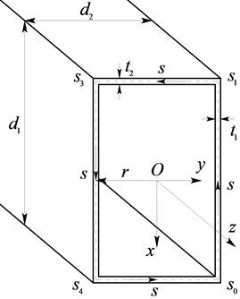
A thin-walled rectangular beam is shown in Fig. 1. The height and width of the cross-section are denoted by and , with corresponding wall thicknesses and , respectively. In the present beam, the thickness is assumed to be much smaller than the other dimensions, and the contour composed of the middle surface of the plates is assumed to be in-extensional [23].
In addition to the Cartesian coordinates (, , ), a right-handed curvilinear coordinate system (, ) is established, with the tangential coordinate measured along the contour anticlockwise. The curvilinear coordinates at the four corner joints are marked as , , , , respectively.
Fig. 1Coordinate systems and structure of a rectangular box beam
Unlike Kim’s beam theory [22], the present theory is concerned about the longitudinal warping displacement and the tangential displacement , neglecting the normal displacement but introducing the transverse bimoment as an alternative to balance and describe the distortion effect. This process avoids the confusion of Kim’s theory in dealing with the in-extensional assumption of the constituting plates. Employing the generalized coordinates, the displacement functions and the transverse bimoment can be written as:
where the generalized displacement vectors are defined as:
and the generalized coordinate vectors defined as:
with the unit transverse inertia moment expressed as:
which is initially mentioned in Vlasov’s work [23].
According to the selected generalized coordinates, corresponding generalized displacements are mechanically meaningful: indicates the longitudinal displacement of the whole cross-section ; and respectively represent the rotation angles about - and - axis; indicates the generalized warping displacement; describes the twist angle of the supposed rigid cross-section , while and are respectively defined as the flexural displacements along and axis, as the generalized distorsion displacement of cross-section.
To formulate the strain field conveniently, a generalized DOF vector is specially constructed as:
Then the non-negligible three-dimensional strain vector can be deduced with the definition of strains as:
where the operator is prescribed as:
with denotes the location along the wall thickness direction. Neglecting insignificant strains, and the strain vector can be obtained as:
with the definition of the matrix :
where , are Young’s and shear modulus, respectively and is Poisson’s ratio.
By definition, the potential energy can be expressed as:
where the distributed force vector is marked as:
with and as the external distributed loads in the axial and tangential directions, and the strain vector of the beam ends is defined as:
where the lines above the parameters denotes the beam ends.
Import in the first displacement field , expressed as:
with the transition matrix marked as:
where the block matrix , and have been defined as Eq. (2). The first displacement field is defined as:
Then the elastic strain energy can be deduced as:
and the loading potential energy is formulated as:
with the equivalent nodal load vector:
where the equivalent nodal loads are defined as:
and the nodal force vector:
where the nodal forces can be prescribed at both ends of a beam as follows:
with new proposed parameters to describe sectional deformations as:
Now it is straightforward to derive the governing equations using the principle of the minimum potential energy as:
3. Finite element implementation for dynamic analysis
continuous interpolation functions is adopted in the present theory as the shape function for ease, since we just explore a possibility of developing a new thin-walled rectangular beam element suitable for dynamic analyses, rather than pursuing the solution convergence. Certainly, more elaborate approaches will definitely improve the solution convergence.
With the linear field approximation, the displacement vector is written as:
where the linear shape function matrix , and the nodal displacement vector are given by:
The two symbols in are assigned as and , respectively with the dimensionless co-ordinate varying from −1 to 1 in an element.
The substitution of Eq. (18) and (19) into Eq. (10) yields an approximate form of the potential energy :
where the potential energy from equivalent nodal forces and the generalized forces acting at nodes are also included. The element stiffness matrix can be obtained with the principle of minimum potential energy as:
and the Jacobian is simply the half of the element length :
The generalized nodal load vector is defined as:
and the generalized distributed load vector is defined as:
To describe the dynamic behavior more accurately, a second displacement field is proposed considering the transverse bending deformation as:
with the transition matrix:
where the third displacement is introduced to represent the transverse deflection of the constituting plates. To satisfy the displacement continuity in the calculation of the kinetic energy, the added generalized coordinate vector is calculated as:
where the unit transverse moment and the harmonic coefficients are written as:
and two boundary conditions expressed as:
The process above finally ensures the displacement continuity, which is critical to the accuracy of the mass matrix.
In order to derive the dynamic equations of motion, Hamilton’s principle [24] is used with the field approximation used for the derivation of the stiffness matrix, and the equations of motion can be obtained as:
where , and are the functions of time , and the consistent mass matrix is given by:
where is the density of the beam material.
Sum up the contribution of all elements and the global motion equations yields:
with:
where is the total number of the thin-walled rectangular box beam elements.
We remark here that the load terms and will be dropped for free vibration analysis of the thin-walled rectangular box beam.
4. Numerical results
For the bending, flexural and axial force effects have been well-settled by Timoshenko and Euler beam theory [26], this section will just be concerned about the twisting, warping and distorsion effects, which are convenient to be compared with Kim’s thin-walled beam theory [22] as well.
The validity of the present beam theory will be tested in this section. Three case studies are conducted and are compared against those by the existing beam theory [22, 26] and the plate theory of NASTRAN [25].
4.1. Case 1: Vibration analysis of a rectangular box beam with a fixed-free end condition
Fig. 2 shows the box beam which is fixed at one end and free at the other end. Structural and material parameters are listed as: , , 7850 kg/m3.
Fig. 2The cantilevered thin-walled rectangular box beam
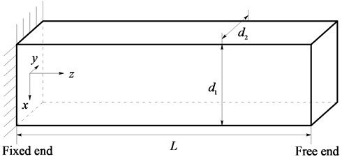
Fig. 3 demonstrates the converging results of the first eigenfrequency of the present theory, which agree well with those obtained from the NASTRAN plate element (element type: QUAD4) [25]. It also shows that the present numerical model is essential to comprise of at least 15 elements to gain satisfactory convergence.
Fig. 3Comparison of the first eigenfrequency convergence for the beam shown in Fig. 2 between the present elements and the NASTRAN plate elements
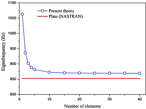
Table 1 lists the first eigenfrequency of the beam in Fig. 2. The conventional beam theory (Timoshenko beam theory [26]) is not useful to predict the first eigenfrequency. The converging results are obtained with 15 present elements and 15 Kim’s revised elements [22], respectively. The present result shows a good agreement with the plate element result, and performs better than Kim’s revised theory as well.
Table 1The first eigenfrequencies of a rectangular beam with a fixed-free end condition
Mode number | Plate | Conventional | Present | Kim’s revised |
1st mode | 852.64 Hz | – | 869.59 Hz | 873.74 Hz |
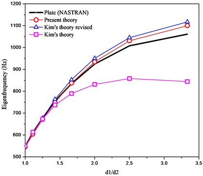
4.2. Case 2: Free vibration analysis of a rectangular box beam with both ends free
Now we will investigate the free vibration of steel rectangular box beams (, , ) with varying values of . The numerical results are obtained with 15 elements.
Fig. 4 shows the first eigenfrequencies of the thin-walled rectangular beam for varying values of . The results obtained by the present box beam elements are compared with the NASTRAN plate element results [25] and Kim’s beam theory [22]. The results in Fig. 4 clearly indicate that the present element gives better results for the wide range of than both Kim’s and Kim’s revised theory [22].
Fig. 4Comparison of variation of the first eigenfrequencies for varying ratios of d1/d2 among the plate, present, Kim’s and Kim’s revised theories
4.3. Case 3: Vibration analysis of a square box beam with a fixed-free end condition
In the case of a square box beam with structural parameters as and , torsional and distortional deformations are uncoupled. The lowest distortional and torsional eigenfrequencies can be calculated by neglecting the deformation of each other.
The results are tabulated in Table 2, which are compared with other results. Actually, the present theory yields a more accurate solution to 569.68 Hz when the elements number added to 40, equal to the result of plate theory of NASTRAN. This fact proves the validity of the present beam theory again.
Table 2The eigenfrequencies of a square box beam with a fixed-free end condition
Mode number | Plate | Conventional | Present (15) | Kim’s revised (15) |
Distorsion | 569.68 Hz | – | 571.94 Hz | 573.78 Hz |
Torsion | 1342.23 Hz | 1359.6 Hz | 1356.1 Hz | 1360.2 Hz |
5. Conclusions
A new eight degree-of-freedom one-dimensional theory is proposed for the dynamic analysis of thin-walled rectangular beams in the present study. Direct kinematic variables representing tension, bending, deflection, torsion, warping and distortion were used so that the present formulation was suitable for the dynamic analyses of thin-walled rectangular beams under various boundary conditions. Two different displacement fields are constructed with different generalized coordinates to establish the stiffness matrix and the mass matrix respectively. The governing differential equations are formulated and expressed with newly proposed parameters to prescribe the cross-section deformations with the principle of minimum potential energy. For the finite element implementation, the stiffness matrix and the mass matrix are substituted into the dynamic equations of motions with Hamilton’s principle. The dynamic equations were approximated with continuous interpolation functions.
At last, several numerical examples were executed and compared with existing theories. The results have confirmed that the present elements accurately predict the dynamic behaviour of the thin-walled rectangular beams.
Work is in progress to develop more general thin-walled beam elements, which is based on the present analysis.
References
-
Sharafi P., Teh L. H., Hadi M. N. S. Shape optimization of thin-walled steel sections using graph theory and ACO algorithm. Journal of Constructional Steel Research, Vol. 101, 2014, p. 331-341.
-
Yu A. M., Yang J. W., Nie G. J., Yang X. G. An improved model for naturally curved and twisted composite beams with closed thin-walled sections. Composite Structures, Vol. 93, Issue 9, 2011, p. 2322-2329.
-
Kim N. I., Jeon C. K. Improved thin-walled finite curved beam elements. Advances in Mechanical Engineering, Vol. 2013, 2013, p. 1-16.
-
Saravia M. C., Machado S. P., Cortínez V. H. A consistent total Lagrangian finite element for composite closed section thin walled beams. Thin-Walled Structures, Vol. 52, 2012, p. 102-116.
-
Abambres M., Camotim D., Silvestre N., Rasmussenc K. J. R. GBT-based structural analysis of elastic–plastic thin-walled members. Computers and Structures, Vol. 136, 2014, p. 1-23.
-
Bischoff M., Wall W. A., Bletzinger K. U., Ramm E. Models and Finite Elements for Thin-Walled Structures. Encyclopedia of Computational Mechanics, Chapter 3, 2004, p. 59-137.
-
Gere J. M. Torsional vibrations of beams of thin-walled open section. Journal of Applied Mechanics-Transactions of the ASME, Vol. 21, Issue 4, 1954, p. 381-387.
-
Ambrosini R. D., Riera J. D., DanesiR. F. Dynamic analysis of thin-walled and variable open section beams with shear flexibility. International Journal for Numerical Methods in Engineering, Vol. 38, Issue 17, 1995, p. 2867-2885.
-
Kim M. Y., Chang S. P., Kim S. B. Spatial stability and free vibration of shear flexible thin-walled elastic beams. I: Analytical approach. International Journal for Numerical Methods in Engineering, Vol. 37, Issue 23, 1994, p. 4097-4115.
-
Kim M. Y., Chang S. P., Kim S. B. Spatial stability and free vibration of shear flexible thin-walled elastic beams. II: Numerical approach. International Journal for Numerical Methods in Engineering, Vol. 37, Issue 23, 1994, p. 4117-4140.
-
Ambrosini R. D., Riera J. D., Danesi R. F. A modified Vlasov theory for dynamic analysis of thin-walled and variable open section beams. Engineering Structures, Vol. 22, Issue 8, 2000, p. 890-900.
-
Bebiano R., Silvestre N., Camotim D. Local and global vibration of thin-walled members subjected to compression and non-uniform bending. Journal of Sound and Vibration, Vol. 315, Issue 3, 2008, p. 509-535.
-
Kim N. I., Lee J. Exact solutions for stability and free vibration of thin-walled Timoshenko laminated beams under variable forces. Archive of Applied Mechanics, Vol. 2014, 2014, p. 1-25.
-
Soltani M., Asgarian B., Mohri F. Finite element method for stability and free vibration analyses of non-prismatic thin-walled beams. Thin-Walled Structures, Vol. 82, 2014, p. 245-261.
-
Duan H. Nonlinear free vibration analysis of asymmetric thin-walled circularly curved beams with open cross section. Thin-Walled Structures, Vol. 46, Issue 10, 2008, p. 1107-1112.
-
Ramkumar K., Kang H. Finite element based investigation of buckling and vibration behaviour of thin walled box beams. Applied and Computational Mechanics, Vol. 7, Issue 2, 2013, p. 155-182.
-
Gendy A. S., SaleebA. F. Vibration analysis of coupled extensional/flexural/torsional modes of curved beams with arbitrary thin-walled sections. Journal of Sound and Vibration, Vol. 174, Issue 2, 1994, p. 261-274.
-
Pagani A., Boscolo M., Banerjeeb J. R., Carreraa E. Exact dynamic stiffness elements based on one-dimensional higher-order theories for free vibration analysis of solid and thin-walled structures. Journal of Sound and Vibration, Vol. 332, Issue 23, 2013, p. 6104-6127.
-
Langseth M., HopperstadO. S. Static and dynamic axial crushing of square thin-walled aluminium extrusions. International Journal of Impact Engineering, Vol. 18, Issue 7, 1996, p. 949-968.
-
Dancila D. S., Armanios E. A. The influence of coupling on the free vibration of anisotropic thin-walled closed-section beams. International Journal of Solids and Structures, Vol. 35, Issue 23, 1998, p. 3105-3119.
-
Cortínez V. H., Piovan M. T. Vibration and buckling of composite thin-walled beams with shear deformability. Journal of Sound and Vibration, Vol. 258, Issue 4, 2002, p. 701-723.
-
Kim Y. Y., Kim J. H. Thin-walled closed box beam element for static and dynamic analysis. International Journal for Numerical Methods in Engineering, Vol. 45, Issue 4, 1999, p. 473-490.
-
Vlasov V. Z. Thin-Walled Elastic Beams. Second Edition, Israel Program for Scientific Translations, Jerusalem, 1961.
-
WashizuK. Variational Methods in Elasticity and Plasticity. Pergamon Press, Oxford, 1982.
-
Nastran M. S. C. Quick Reference Guide, MSC. Reversion 0, Software Corporation, 2010.
-
Timoshenko S. P., Gere J. M. Theory of Elastic Stability. Courier Dover Publications, 2009.
About this article

This work is supported by Program for Chang Jiang Scholars and Innovative Research Team in University (PCSIRT) (Grant No. IRT1292), and A Project Funded by the Priority Academic Program Development of Jiangsu Higher Education Institutions (PAPD).
