Abstract
The present paper is concerned with the transverse vibration properties of an axially moving nested clamped-hinged beam, which can be regarded as a stepped beam. The transverse vibration equation for the axially moving nested clamped-hinged beam is derived by D’Alembert’s principle. The modified Galerkin’s method, which uses the instantaneous modal function of the clamped-hinged stepped beam as a trial function, is used to solve the vibration equation. An axially moving nested clamped-hinged beam model is designed for the vibration test. The theoretical model is updated by calculating the flexural rigidity values of the first segment of the nested beam based on the measured first-order vibration frequencies, which are tested for different lengths in the main beam. The first order decay coefficients are identified by the logarithmic decrement method. Then, the functional relationship between the flexural rigidity and beam length, as well as the decay coefficient and beam length, is established using the polynomial fitting method. The calculated responses of the modified model agree well with the experimental results, which verifies the correctness of the proposed calculation model and indicates the effectiveness of the methods of model updating and damping determination. The theoretical and experimental results demonstrate that the change law of the frequency with the main beam length increasing is a low-high-low-high trend. Further investigations into the non-damping free vibration properties of the nested clamped-hinged beam during extension and retraction of the main beam are performed. It is determined that there is no obvious change of the dynamic response amplitude of the nested structure during different axial moving rates in the main beam. Furthermore, as the length of the main beam increases, the vibration displacement decreases gradually, and the total mechanical energy increases constantly; therefore, the extension movement of the main beam becomes unstable. Moreover, the numerical results indicate that the non-damping free vibration characteristics of the nested clamped-hinged beam during extension and retraction of the main beam are inversely related.
1. Introduction
The dynamic problems of a beam subjected to moving structures have been widely investigated in the engineering field for a very long time. The studies have employed various moving models, among which four types of models have been most frequently used, i.e., the moving force model, moving mass model, moving oscillator model, and moving beam model. However, the vibration problem of an axially moving nested structure cannot be solved using these models. The transverse dynamic responses of the moving beam and fixed beam are mutually consistent at the same location of the nested structure; therefore, the two beams should be considered as a whole. A typical engineering example of the nested beam model is a steel bridge that moves along its guiding beam. The nested beam can be assumed to be a non-uniform beam at any instant during the movement of the main beam. To analyze the vibration properties of the axially moving nested beam model, it is necessary to combine the dynamic studies of an axially moving uniform beam with the calculation method for the natural vibration characteristics of a non-uniform beam.
Several studies have been conducted on the dynamic responses, stability and vibration control of an axially moving uniform beam. Tabarrok et al. [1] derived the dynamic equation of a deploying beam by using the Lagrange method and the assumed mode method. Stylianou and Tabarrok [2, 3] developed a finite element model, where the number of elements is fixed but their sizes change in a prescribed fashion, and illustrated its use through time-integration of equations of motion for axially moving beams. Then, the dynamic stability characteristics of the flexible extendible beam were examined. Al-Bedoor and Khulief [4] introduced a systematic approach to obtain an approximate analytical solution for the transverse vibrations of an elastic beam during axial deployment. Fung et al. [5] employed Hamilton’s principle to derive the governing equations of motion for a deploying beam with a tip mass. The dynamic stability of the continuous media relative to the inertial and moving coordinate systems was studied by Zhu and Ni [6] from an energy standpoint. Zhu et al. [7] investigated the vibration stability and control strategy for translating beams and strings with arbitrarily varying lengths. The non-linear transverse vibrations of an axially traveling Euler-Bernoulli beam were investigated by Öz et al. [8], and the method of multiple scales was applied to the equation of motion in search of approximate solutions. Lee and Oh [9] numerically investigated the effects of viscoelasticity and moving speed on the dynamics and stability of moving beams using a spectral element model. Ghayesh and Balar [10] studied the non-linear parametric vibration and stability of an axially moving visco-elastic Rayleigh beam. Chang et al. [11] used a finite element method with variable-domain elements to derive the equations of motion of an axially moving beam based on Rayleigh beam theory. Wang et al. [12] derived the transverse vibration equation of an axially moving cantilever beam with a tip mass by using D’Alembert’s principle and updating it with experiments, then investigated active control of the vibration of an iron cantilever beam with axial velocity.
The solutions for dynamic characteristics, such as natural frequency, modal loss factor and modal function of a non-uniform beam, have been investigated extensively. Gupta [13] presented numerical solutions of the natural frequency and modal for a circular section beam with a linear variation of the diameter by using the finite element method. Caruntu [14] investigated the non-linear vibration problem of a rectangular section beam with a parabolic change of the thickness. Mehmet [15] studied the vibration properties of a non-uniform rectangular beam where the cross section width changes via a power exponential function. Mao et al. [16, 17] used the Adomian Decomposition Method to investigate the transverse vibration of a stepped beam. Cui et al. [18] developed a semi-analytical approach to calculate the natural frequency and modal function of arbitrary variable cross-section beams.
Duan et al. [19] investigated the transverse vibration properties of an axially moving nested cantilever beam, but there are many differences in physical meaning, dynamic theoretical analysis, solution method for vibration equation, boundary condition updating and vibration property laws between the previous model and the axially moving nested clamped-hinged beam model. In this paper, the theoretical model of transverse dynamic response for an axially moving nested clamped-hinged beam is established based on the presented studies. The calculation method for the natural vibration characteristics of a clamped-hinged stepped beam is introduced. Then, the equation of motion is solved using the modified Galerkin’s method. Through the nested clamped-hinged beam model experiments, the theoretical model is updated, and the damping is determined. The calculation results of the dynamic responses for the nested beam are compared with the experimental results to verify the correctness of the proposed theoretical model. Lastly, the non-damping free vibration characteristics of the nested clamped-hinged beam are investigated during the extension and retraction process of the main beam.
2. Theoretical model of dynamic response for an axially moving nested clamped-hinged beam
2.1. Equation of motion
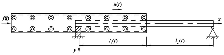
Fig. 1 shows a dynamic model of a single-span clamped-hinged beam (guiding beam) subjected to a moving structure (main beam), which can be regarded as a nested structure. In this model, the guiding beam is a solid rectangular section beam. The main beam is a sleeve installed with several groups rollers, the underside rollers are installed symmetrically on both sides, and the main beam can move along the guiding beam by cutting a gap in the undersurface of it. At any instant, the nested clamped-hinged beam can be simplified into a non-uniform Euler-Bernoulli beam with flexural rigidity and mass per unit length varying along the beam. The main beam is assumed to be extensible with an arbitrarily prescribed translational velocity , where is time, and is a driving force for the axial movement. The instantaneous lengths of the first and second segment of the nested beam are and , respectively. Relative to the fixed coordinate system shown in Fig. 1, the transverse displacement of the nested beam located at spatial position , where , is . The external damping of the structure is considered in our research, and the damping coefficient is . The axial telescopic deformation of the beam is ignored.
Fig. 1Schematic of an axially moving nested clamped-hinged beam system
By establishing the transverse force balance [19], the equation of motion is derived as follows:
where, because the main beam is translating axially, it can be obtained as:
and, as the guiding beam is inextensible, it can be given by:
In this nested beam model, the transverse external load is:
The modified Galerkin’s method, which uses the instantaneous modal function of the clamped-hinged stepped beam as a trial function, is generally used to truncate the vibration equation to a set of time-dependent ordinary differential equations. The solution to the displacement can be expressed as a superposition of every mode, and it has a form as follows:
where is the number of modes; are the generalized coordinates; and are the instantaneous vibration mode expressions of the nested beam.
Therefore, it is necessary to obtain the vibration mode expressions for a nested clamped-hinged beam of a certain length, which can be simplified into a clamped-hinged stepped beam. The analysis method for the natural vibration characteristics of the clamped-hinged stepped beam is introduced in the next section.
2.2. Calculation method for the natural vibration characteristics of a clamped-hinged stepped beam
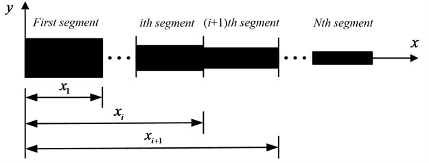
Fig. 2 illustrates the stepped beam, which is composed of uniform cross-section segments. The beam length, flexural rigidity and mass per unit length of the th segment are denoted by , and ( 1, 2,…, ), respectively.
Fig. 2Stepped beam with N segments
Based on the modal function of the uniform beam, the modal function of the th segment of the stepped beam is given as follows:
where ( 1, 2,…, ). , , , are undetermined coefficients of the modal function of the th segment of the stepped beam, which are determined by the boundary conditions of the beam end. is defined as follows:
where is the natural frequency of the entire stepped beam.
Similarly, the modal function for the (1)th segment of the stepped beam can be expressed as follows:
Based on the continuity conditions of the displacement, corner, moment and shear of both the right end of the th segment and the left end of the (1)th segment, four equations can be obtained as follows:
By substituting Eqs. (8) and (10) into Eqs. (11)-(14), we obtain:
where:
Because in Eq. (15), the relation between and is derived as follows:
where:
Each element in the matrix is a function of the natural frequency . Furthermore, the expression for the natural frequency can be obtained by substituting the four boundary conditions at the ends of the beam into Eq. (17).
The boundary conditions at the ends of the clamped-hinged stepped beam are given as follows:
It can be obtained from Eq. (19) that:
Based on Eq. (20), a matrix equation can be written in the form:
where:
By substituting Eq. (17) into Eq. (22), we can obtain:
where:
By substituting Eq. (21) into Eq. (24), we can obtain:
To obtain a nonzero solution for Eq. (26), its coefficient matrix determinant must be equal to zero, and the characteristic equation of a clamped-hinged stepped beam can be derived as follows:
The characteristic Eq. (27) is a nonlinear function of , which can be calculated using the Newton-Raphson method. Then, we can obtain the modal functions of the clamped-hinged stepped beam by substituting into Eq. (8). The validity of the above method has been validated in [18].
2.3. Solution to the equation of motion using the modified Galerkin’s method
The nested clamped-hinged beam shown in Fig. 1 can be simplified into a clamped-hinged stepped beam with two segments at any instant during the movement of the main beam, and both segments are uniform. Let the flexural rigidity and mass per unit length be and for the first segment of the stepped beam, respectively, while the second segment of the stepped beam has flexural rigidity and mass per unit length . The dynamic forces acting on the main beam and guiding beam should each be analyzed in solving the vibration equation of the nested beam. As the model in this study is symmetrical, the flexural rigidity and mass per unit length of the main beam are represented by and , respectively.
Eq. (1) can be solved using the modified Galerkin’s method, which uses the instantaneous modal function of the clamped-hinged stepped beam as a trial function. At any instant, the transverse vibration displacement response of the main beam can be expressed as:
where is the modal function of the first segment of the clamped-hinged stepped beam, is the variable substitution function of , and:
The transverse vibration displacement response of the guiding beam can be written as:
where is the modal function of the second segment of the clamped-hinged stepped beam.
The above-mentioned modal functions can be calculated using the method provided in Section 2.2.
Considering the effects of axial velocity on the dynamics of the main beam, differential equations of the transverse vibration displacement of the main beam can be written as:
Based on the displacement response expression of the guiding beam in Eq. (30), it can be obtained as:
By substituting Eqs. (31)-(40) into Eq. (1), multiplying the transverse vibration equation by , and , integrating it over the domain [0, ], and assuming the damping effect is Rayleigh damping (, where is the damping ratio of the th modal and is the natural frequency of the th modal), the discretized equations of motion for the axially moving nested cantilever beam with time-dependent coefficient matrices can be obtained as follows:
where is the mass matrix; is the damping matrix; is the stiffness matrix; and is the load vector. The entries of these matrices are given as follows:
3. Model test
3.1. The platform for vibration testing of an axially moving nested clamped-hinged beam
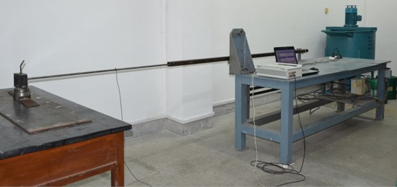
A photo and schematic diagram of the test platform are presented in Fig. 3 and Fig. 4, respectively. The platform consists of a table, motor, frequency converter, lead screw, driving block, belt, supports, main beam and guiding beam. The power equipment can push and pull the main beam with deploying and retracting movements. The main beam is constructed of cold bent square hollow steel with a side length of 0.04 m and a wall thickness of 0.003 m, and the mass per unit length of the main beam (including rollers) is 4.622 kg/m. The guiding beam is solid rectangular section steel with an axial length of 2 m, and the width and height of its cross section are 0.03 m and 0.012 m, respectively. The mass density and Young’s modulus of the guiding beam are 7800 kg/m3 and 2.1×10¹¹ N/m2, respectively. The mass of the acceleration transducer is so small (0.002 kg) that it can be ignored in the calculation.
Fig. 3Photograph of the test platform
3.2. The overall vibration form of the nested test beam
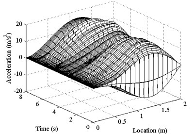
To illustrate the overall vibration form of the nested clamped-hinged beam at different times, the acceleration response of the entire beam is calculated during the axial movement of the main beam.
Based on the test beam, the properties of the structure are given as: 0.4 m, 7.43 kg/m, 9000 N·m2, 0.4 m, 2.81 kg/m, 907.2 N·m2 and the initial displacement of the midspan of the nested beam is 0.0015 m. Fig. 5 presents the overall vibration form of the nested beam without regard to damping during the extension of the main beam, with constant velocities of 0.2 m/s. It can be determined that the maximum acceleration response of the nested beam has arisen between 1.2 m and 1.4 m during the movement of the main beam. Therefore, it is preferable to stick an acceleration transducer on the nested beam at 1.3 m in experiments.
Fig. 4Schematic diagram of the test platform
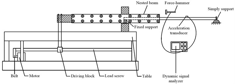
Fig. 5Overall vibration form of the nested clamped-hinged beam
3.3. Theoretical calculation model updating
There is a small gap between the main beam and the guiding beam. The contact between them varies when the nested beam vibrates under the external-excitation during the axial movement of the main beam, which is difficult to simulate in the theoretical calculation model. However, the left main beam part of the clamped support is likely to affect the dynamic response of the nested structure. Therefore, a correction is required. The updating method is as follows: By adjusting the multiple lengths of the main beam, the first-order vibration frequency of the nested structure in each length is derived using the force-hammer striking method. The theoretical flexural rigidities of the first segment of the nested clamped-hinged beam are calculated using the method in Section 2.2, based on the measured frequencies; then, the relationship between the theoretical flexural rigidity and the measured length of the first segment of the nested beam is established with the polynomial fitting method. The length of the first segment of the nested beam varies from 0.480 m to 1.041 m in the experiment. Fig. 6(a) and Fig. 6(b) presents the frequency response function curves of the nested beam and the coordinates of the first-order vibration frequency when the lengths of the first segment are 0.515 m and 1.020 m, respectively, where the ordinate represents the logarithmic amplitude of the acceleration frequency response function. The measured first order vibration frequencies and the corresponding theoretical flexural rigidities for different lengths in the nested beam are presented in Table 1, and it can be concluded that the updating method for the theoretical model is reasonable because the theoretical and measured flexural rigidity is on the same order of magnitude.
Fig. 6Measured frequency response function curves of the nested beam
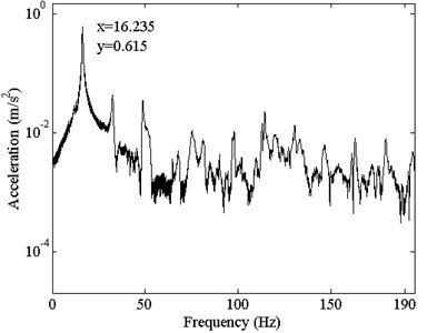
a)0.515 m
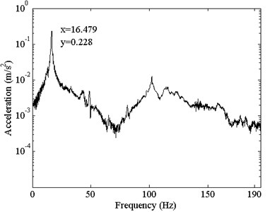
b)1.020 m
Fig. 7Relation of the fitting order with RMSE for the theoretical flexural rigidity function
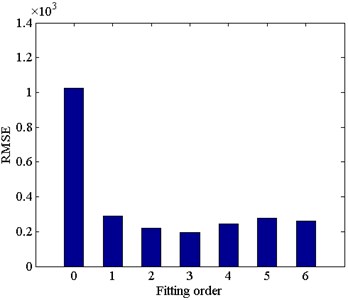
Fig. 8Fitting curve of the theoretical flexural rigidity and the measured length
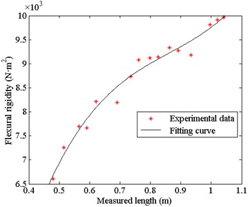
Table 1Measured first-order vibration frequencies and the corresponding theoretical flexural rigidities for different lengths in the nested beam
Serial number | (m) | (m) | Frequency (Hz) | (×103 N·m2) |
1 | 0.480 | 1.520 | 15.747 | 6.6055 |
2 | 0.515 | 1.485 | 16.235 | 7.2602 |
3 | 0.565 | 1.435 | 16.724 | 7.6957 |
4 | 0.591 | 1.409 | 16.846 | 7.6685 |
5 | 0.621 | 1.379 | 17.212 | 8.2128 |
6 | 0.690 | 1.310 | 17.334 | 8.1984 |
7 | 0.735 | 1.265 | 17.578 | 8.7308 |
8 | 0.762 | 1.238 | 17.700 | 9.0754 |
9 | 0.799 | 1.201 | 17.578 | 9.1174 |
10 | 0.825 | 1.175 | 17.456 | 9.1421 |
11 | 0.862 | 1.138 | 17.334 | 9.3295 |
12 | 0.892 | 1.108 | 17.090 | 9.2720 |
13 | 0.934 | 1.066 | 16.724 | 9.1810 |
14 | 0.996 | 1.004 | 16.602 | 9.8098 |
15 | 1.020 | 0.980 | 16.479 | 9.9135 |
16 | 1.041 | 0.959 | 16.357 | 9.9667 |
The function between and in Table 1 is set up with the polynomial fitting method, and the fitting order is determined by the cross validation method [20]. The root mean squared error (RMSE) of each fitting order is presented in Fig. 7, and it can be observed that the third order is the best fitting order. The fitting curve for the theoretical flexural rigidity value is depicted in Fig. 8. Then, is expressed as a cubic function of , which varies from 0.480 m to 1.041 m as follows:
3.4. Damping determination of the axially moving nested clamped-hinged beam with varying length
The damping of the nested beam is varied when the main beam experiences axial movement. The following method is used to obtain the first-order damping of the test beam. The nested beam lengths selected in the damping test are the same as those in the theoretical model updating test as listed in Table 1. A weight is hung on the nested beam at 1.1 m to obtain a similar deformation as the first-order modal shape. The acceleration response of the nested beam is measured after the static load is suddenly released. Fig. 9(a) and Fig. 9(b) present the acceleration response attenuation curves of the nested beam at 1.3 m when the lengths of the first segment are 0.515 m and 1.020 m, respectively. It can be observed that the first-order modal is the major modal excited by the vertical load near the midspan of the nested beam, and high-order modals decay quickly; therefore, it is reasonable to analyze the first-order vibration under the above-mentioned condition. The first-order decay coefficient, (, where is the first-order natural frequency and is the damping ratio), is identified by the modulation envelope of the acceleration response attenuation curve. The obtained first-order decay coefficients for different lengths in the first segment of the nested beam are presented in Table 2.
Fig. 9Measured acceleration response attenuation curves of the nested beam at 1.3 m
a)0.515 m
b)1.020 m
Table 2Identified first-order decay coefficients for different lengths in the first segment of the nested beam
Serial number | (m) | Decay coefficient | Serial number | (m) | Decay coefficient |
1 | 0.480 | 0.9573 | 9 | 0.799 | 1.7333 |
2 | 0.515 | 0.9152 | 10 | 0.825 | 1.5053 |
3 | 0.565 | 0.9452 | 11 | 0.862 | 0.994 |
4 | 0.591 | 1.3326 | 12 | 0.892 | 1.1731 |
5 | 0.621 | 0.9352 | 13 | 0.934 | 1.0959 |
6 | 0.690 | 1.5179 | 14 | 0.996 | 1.4287 |
7 | 0.735 | 1.1471 | 15 | 1.020 | 1.138 |
8 | 0.762 | 1.8410 | 16 | 1.041 | 1.3321 |
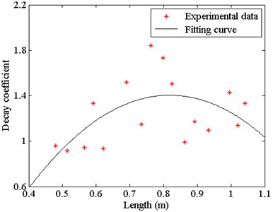
The relationship between the decay coefficients and the measured lengths of the first segment of the nested beam is established by the polynomial fitting method. The root mean squared error (RMSE) of each fitting order is presented in Fig. 10. Although the fourth order is the best one, the second fitting order is good enough for the analysis. Considering the convenience of calculation, the second fitting order is used in the decay coefficient fitting. The fitting curve for the decay coefficient is depicted in Fig. 11, and the experimental decay coefficients are quite scattered because the present paper take the external damping into consideration, and the variation characteristic of the external damping is very difficult to predominate because the contact surfaces between the main beam and the guiding beam vary continuously during the movement of the main beam. Lastly, the decay coefficient is expressed as a quadratic function of the measured length of the first segment as follows:
Fig. 10Relation of fitting order with RMSE for decay coefficient function
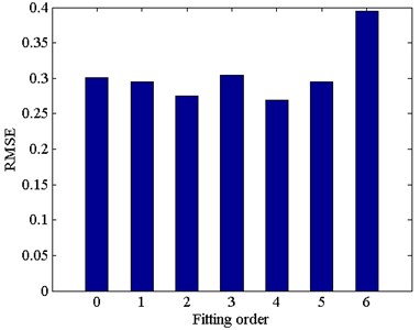
Fig. 11Fitting curve of decay coefficient and measured length
3.5. Comparison between the numerical results of the updated model and the experimental results
The study of the dynamic response of the nested clamped-hinged beam model can be performed after the theoretical model is corrected and the damping is obtained. The theoretical results of the acceleration responses of the first-order model for the nested beam during the extension and retraction of the main beam are compared with the experimental results in this section.
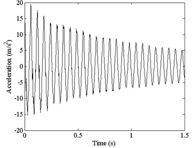
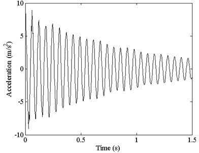
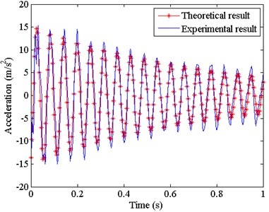
The axial velocity of the main beam is controlled by the motor rotational speed, which is regulated by a frequency converter. Thus, the axial velocity can be obtained at a certain frequency converter reading. The test process is as follows: A heavy mass of four kilograms is suspended at 1.1 m from the clamped support of the nested beam, which leads to the initial deformation. The main beam moves along the axis with constant velocities of 2.475 cm/s and 3.140 cm/s. When the main beam stretches to 0.885 m, the heavy mass is removed. Then, the corresponding acceleration responses of the nested beam at 1.3 m are measured. The comparison between the measured results and the updated theoretical results is presented in Fig. 12. It can be determined that the agreement between the calculated responses with the updated theoretical model and the experimental results is evident, which verifies the correctness of the proposed theoretical calculation model and explains the effectiveness of the theoretical model correction method and damping determination.
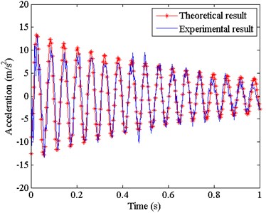
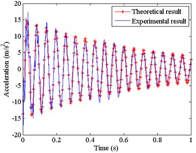
During the retraction, we release the heavy mass when the length of the main beam is 0.768 m. Fig. 13(a) and Fig. 13(b) provide the comparison between the updated theoretical and experimental acceleration responses when the axial velocities of the beam are –2.475 cm/s and –3.140 cm/s, respectively. Thus, it is proven that the calculated responses using the updated model are in accordance with the experimental results.
It is observed that slight deviations exist between the test results and the corrected theoretical results. The deviations are primarily caused by two factors: One is that the vibration generated by the motor is transferred to the beam via the transmission mechanism; another is that some high-order modes of vibration of the nested beam are excited by the vibration of the test platform. Moreover, the main beam cannot execute high-speed movements because of the limitation of the driving device.
Fig. 12Comparison between the theoretical and experimental results
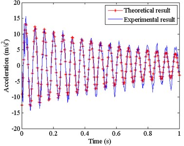
a) 2.475 cm/s
b) 3.140 cm/s
Fig. 13Comparison between the theoretical and experimental results
a) –2.475 cm/s
b) –3.140 cm/s
4. Study on non-damping free vibration of an axially moving nested clamped-hinged beam
4.1. Vibration frequency analysis
To observe the vibration frequency change law of the nested clamped-hinged beam during axial movement of the main beam, 28 results of frequency have been measured while the length of the main beam varies from 0.480 m to 1.838 m (for the limitation of the test platform, the main beam cannot move along the guiding beam in overall length). Then, is expressed as a fifth degree polynimial function of , which varies from 0.480 m to 1.838 m as follows:
The vibration frequency of the nested beam while the length of the first segment changes from 0.480 m to 1.838 m can be calculated based on the fitting flexural rigidity. The comparison between the measured frequency and the theoretical frequency is presented in Fig. 14. It can be determined that the change law of the frequency with the main beam length increasing is the trend of low-high-low-high, and the frequency increases quickly when the length of the main beam is greater than 1.5 m.
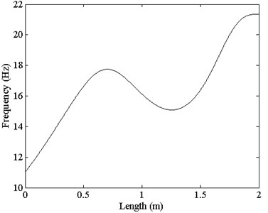
Under ideal conditions, let 9000 N·m2; as the length of the first segment of the nested beam varies from 0 to 2 m, the theoretical frequency of the nested beam is presented in Fig. 15, and the same change law can be observed.
Fig. 14Comparison between the measured and theoretical frequency
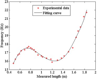
Fig. 15Vibration frequency of the test beam under ideal conditions
4.2. Dynamic characteristics analysis
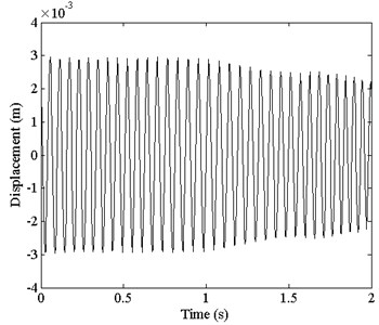
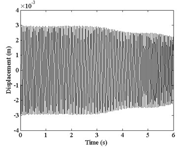
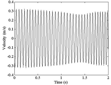
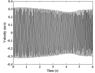
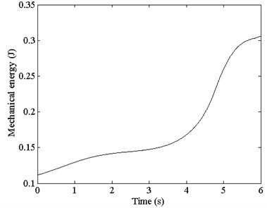
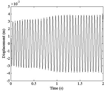
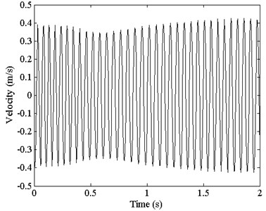
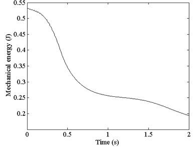
Further study on the non-damping free vibration properties of the axially moving nested clamped-hinged beam during extension and retraction are implemented based on the above-mentioned reports. We assume that the main beam deploys with a constant velocity of 0.6 m/s and 0.2 m/s, respectively. When the deployed length of the main beam is 0.6 m, the nested beam vibrates under the action of external-excitation, and the initial displacement of the nested beam at 1.3 m is 0.003 m. Then, the nested beam is in the free vibration period with axial extension. The flexural rigidity of the first segment of the nested beam is determined by Eq. (48). Fig. 16(a)-(d) provide the displacement and velocity responses of the non-damping vibration of the nested beam at 1.3 m during different extending velocities in the main beam, respectively. As the length of the main beam increases, the vibration displacement decreases gradually. The vibration speed decreases as the main beam extends to 1.3 m, and then it increases constantly. Also, there is no obvious difference in the dynamic response amplitude of the nested structure during different extension velocities in the main beam. Therefore, the extending velocity of the main beam can be increased for reducing the vibration significantly in the practical engineering problems. To analyze motion stability of the nested beam, the total mechanical energy of the transverse vibration of the nested beam is calculated. As shown in Fig. 16(e) and (f), the amplitude of the total mechanical energy for different extending velocities in the main beam is almost the same during the free vibration period, and it increases continuously. Therefore, the free vibration of the nested beam during the extension becomes unstable. This stability law of axially moving nested clamped-hinged beams is inversely related to that of cantilever beams [6, 7] and nested cantilever beams [19] during extension.
Now, suppose the main beam retracts with a constant velocity of –0.6 m/s and –0.2 m/s, respectively. When the length of the main beam is 1.8 m, the transverse vibration of the entire structure occurs under the action of external-excitation, and the initial displacement at 1.3 m is 0.003 m. Then, the nested beam is in the free vibration period with axial retraction. The displacement responses of the non-damping vibration of the nested beam at 1.3 m during different retracting velocities in the main beam are provided in Fig. 17(a) and (b), respectively. The figures display opposite trends compared to Fig. 16(a) and (b). The vibration speed response shown in Fig. 17(c) and (d) illustrate a similar law to that in Fig. 16(c) and (d). Fig. 17(e) and (f) provide the total mechanical energy of the transverse vibration of the nested beam during different retracting velocities in the main beam, which decreases constantly. Therefore, the free vibration of the nested beam during the retraction remains stable.
Fig. 16Responses of the nested beam at 1.3 m and the total mechanical energy
a) 0.6 m/s
b) 0.2 m/s
c) 0.6 m/s
d) 0.2 m/s

e) 0.6 m/s
f) 0.2 m/s
Fig. 17Responses of the nested beam at 1.3 m and the total mechanical energy
a) –0.6 m/s
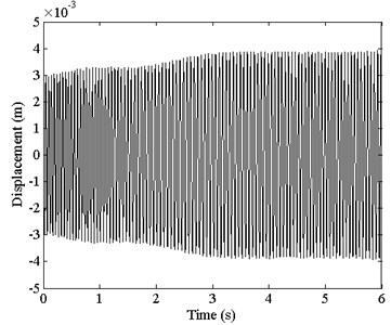
b) –0.2 m/s
c) –0.6 m/s
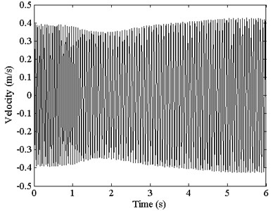
d) –0.2 m/s
e) –0.6 m/s

f) –0.2 m/s
5. Conclusions
An axially moving nested clamped-hinged beam is a type of time-varying nonlinear system that can be regarded as a clamped-hinged stepped beam. The solution method for the dynamic characteristics of the model is introduced for the first time. The transverse vibration equation of the model is established using D’Alembert’s principle. The axial movement effect of the main beam is considered, and the vibration equation can be solved using a modified Galerkin’s method.
The theoretical and experimental study of the dynamic response of the nested clamped-hinged beam model is performed on the basis of the theoretical model update and damping determination. The calculated results for the acceleration response of the nested beam, during both extension and retraction, agree well with the experimental data, which proves the validity and reliability of both the theoretical and experimental analysis.
The non-damping free vibration characteristics of the axially moving nested clamped-hinged beam are studied. It is determined that the increase in the moving velocity of the main beam can reduce the vibration of the nested beam significantly, but the amplitude of the dynamic responses and the total mechanical energy in the free vibration period cannot be increased obviously during extension or retraction. Furthermore, as the length of the main beam increases during extension, the vibration displacement decreases gradually, while the total mechanical energy increases constantly; therefore, the free vibration of the nested beam during the extension becomes unstable. The results indicate that non-damping free vibration characteristics of the nested clamped-hinged beam during extension and retraction are inversely related.
The model presented in this paper can be applied to the dynamic response studies of axially moving nested structures with clamped-clamped, hinged-hinged or clamped-sliding supports. The difference among these models is the solution to the natural vibration characteristics.
References
-
Tabarrok B., Leech C. M., Kim Y. I. On the dynamics of an axially moving beam. Journal of the Franklin Institute, Vol. 297, Issue 3, 1974, p. 201-220.
-
Stylianou M., Tabarrok B. Finite element analysis of an axially moving beam, Part I: Time integration. Journal of Sound and Vibration, Vol. 178, Issue 4, 1994, p. 433-453.
-
Stylianou M., Tabarrok B. Finite element analysis of an axially moving beam, Part II: Stability analysis. Journal of Sound and Vibration, Vol. 178, Issue 4, 1994, p. 455-481.
-
Al-Bedoor B. O., Khulief Y. A. An approximated analytical solution of beam vibrations during axial motion. Journal of Sound and Vibration, Vol. 192, Issue 1, 1996, p. 159-171.
-
Fung R. F., Lu P. Y., Tseng C. C. Non-linearly dynamic modeling of an axially moving beam with a tip mass. Journal of Sound and Vibration, Vol. 218, Issue 4, 1998, p. 559-571.
-
Zhu W. D., Ni J. Energetics and stability of translating media with an arbitrarily varying length. Journal of Vibration and Acoustics, Transactions of the ASME, Vol. 122, Issue 3, 2000, p. 295-304.
-
Zhu W. D., Ni J., Huang J. Active control of translating media with arbitrarily varying length. Journal of Vibration and Acoustics, Transactions of the ASME, Vol. 123, Issue 3, 2001, p. 347-358.
-
Öz H. R., Pakdemirli M., Boyaci H. Non-linear vibrations and stability of axially moving beam with time-dependent velocity. International Journal of Non-linear Mechanics, Vol. 36, Issue 1, 2001, p. 107-115.
-
Lee U., Oh H. Dynamics of an axially moving viscoelastic beam subject to axial tension. International Journal of Solids and Structures, Vol. 42, Issue 8, 2005, p. 2381-2398.
-
Ghayesh M. H., Balar S. Non-linear parametric vibration and stability of axially moving visco-elastic Rayleigh beams. International Journal of Solids and Structures, Vol. 45, Issue 25-26, 2008, p. 6451-6467.
-
Chang J. R., Lin W. J., Huang C. J., Choi S. T. Vibration and stability of an axially moving Rayleigh beam. Applied Mathematical Modeling, Vol. 34, Issue 6, 2010, p. 1482-1497.
-
Wang L., Chen H. H., He X. D. Active H∞ control of the vibration of an axially moving cantilever beam by magnetic force. Mechanical Systems and Signal Processing, Vol. 25, Issue 8, 2011, p. 2863-2878.
-
Gupta A. K. Vibration of tapered beams. Journal of Structural Engineering, Vol. 111, Issue 1, 1985, p. 19-36.
-
Caruntu D. On Nonlinear Vibration of Non-Uniform Beam with Rectangular Cross-Section and Parabolic Thickness Variation. Solid Mechanics and its Applications, Kluwer Academic Publishers, Dordrecht, Boston, London, 2000.
-
Mehmet C. E., Metin A., Vedat T. Vibration of a variable cross-section beam. Mechanics Research Communications, Vol. 34, Issue 1, 2007, p. 78-84.
-
Mao Q., Pietrzko S. Free vibration analysis of stepped beams by using adomian decomposition method. Applied Mathematics and Computation, Vol. 217, Issue 7, 2010, p. 3429-3441.
-
Mao Q. Free vibration analysis of multiple-stepped beams by using adomian decomposition method. Mathematical and Computer Modeling, Vol. 54, Issue 1-2, 2011, p. 756-764.
-
Cui C., Jiang H., Li Y. H. Semi-analytical method for calculating vibration characteristics of variable cross-section beam. Journal of Vibration and Shock, Vol. 31, Issue 14, 2012, p. 85-88.
-
Duan Y. C., Wang J. P., Wang J. Q., Liu Y. W., Shao F. Theoretical and experimental study on the transverse vibration properties of an axially moving nested cantilever beam. Journal of Sound and Vibration, Vol. 333, Issue 13, 2014, p. 2885-2897.
-
Stoica P., Eykhoff P., Janssen P., Soderstrom T. Model-structure selection by cross-validation. International Journal of Control, Vol. 43, Issue 6, 1986, p. 1841-1878.
About this article

The research is supported by the Major State Basic Research Development Program of China (Project Nos. 2014CB046801 and 2014CB046804).
