Abstract
Dynamic responses of a telescopic mechanism for truss structure bridge inspection vehicle under moving mass are investigated under the assumption of Euler-Bernoulli beam theory. Equations of motion for the telescopic mechanism are derived using the Hamilton’s principle. The equations are transformed into discretized equations by employing the Galerkin’s method. The eigenfunctions of the beams are derived based on the kinetic and dynamic boundary conditions. The time-dependent features of the eigenfunctions are taken into account. The discretized equations are solved utilizing the Newmark- method. Numerical results are presented to explore the influence of the moving mass on the dynamic responses of the telescopic mechanism and find appropriate mass-moving strategy to avoid large vibration. The results show that the vibrations when the mass doesn’t move synchronously with the telescopic beam are not always the minimum; on the other hand, the mass moving in the same direction of the telescopic beam will bring in stronger vibration.
1. Introduction
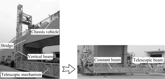
Truss structure bridge inspection vehicle is a special vehicle that provides working plat (i.e., telescopic mechanism) for maintenance staff under the bridge (Fig. 1). Modern telescopic mechanism is being built to be in large length and outreach, making the telescopic mechanism susceptible to vibration. Hence, in general, synchronous motion of the mass on the telescopic mechanism is not conducted. However, in reality, the mass is expected to move synchronously on the telescopic mechanism to keep away from obstacles or quickly reach a certain position, which can greatly improve the working efficiency. Whether the moving mass will really bring about larger vibration is not known. Therefore, attention should be paid to the dynamic responses of the telescopic mechanism under synchronously moving mass and explore which mass-moving strategy is better for reducing the vibration.
Fig. 1Truss structure bridge inspection vehicle
The telescopic mechanism generally consists of one constant beam and one or two telescopic beams. Many studies have been published to investigate dynamic characteristics of axially moving beams over the years. Öz and Pakdemiorli [1] analyzed dynamic response of an axially accelerating, elastic and tensioned beam with a harmonically varying velocity about a constant mean and presented the effects of the velocity fluctuation frequency on the stability. Chen et al. [2] investigated transversely parametric vibration of a viscoelastic tensioned beam with an axially harmonically varying speed about a constant mean velocity. Chen and Zhao [3] employed an integro-partical-differential equation to investigate free nonlinear transverse vibration of an axially moving beam. Usik and Hyungmi [4] derived a spectral element model to analyze the dynamics and stability of an axially moving viscoelastic beam that is subjected to axial tension and the influence of viscoelasticity and moving speed on the dynamics and stability was discussed. Piovana and Sampaiob [5] addressed vibration characteristics of an axially moving flexible beam made of functionally graded material with a tip mass by interpreting the beam into a telescopic beam system. Wang et al. [6] used an axially telescoping cantilever beam to analyze coupling dynamic response between the translation and the flexible deformation of an extending or retracting spacecraft antenna. Liu et al. [7] obtained dynamic responses of an axially moving viscoelastic beam subjected to a randomly disordered periodic excitation and analyzed the effects of the stochastic jump on the stability of the system. Mergen and Marco [8] investigated the transverse vibration response, stability and bifurcations of an axially moving viscoelastic beam at time-dependent speed. Park et al [9] compared the vibrations of an axially deploying beam of Eulerian and Lagrangian descriptions. These studies have addressed the dynamic responses of single axially moving beam.
Dynamics of multistage beams has been studied over the past years. Vibration of a truck crane telescopic boom extending to the maximum length was analyzed in [10, 11] with the connections simplified as fixed springs at the slide block locations. Modal representation of a fire recuse ladder was obtained by assuming the two beams to be a three-stage geometrically discontinuous beam system in [12]. However, these studies assumed the beams reached their maximum length and the axial motion was not taken into account. Barthels and Wauer [13] investigated the bending vibrations of geometrically nonlinear beams with some clearance in the contact areas during extension or retraction. Zhang et al. [14] interpreted an axially deploying-and-retracting wing to be a cantilever laminated composite beam and estimated the influence of axially moving velocity on the nonlinear dynamic behaviors of the wing. Raftoyiannis and Michaltsos [15] established a dynamic analytical model to study the dynamic characteristics of a simply supported telescopic crane boom under tip load when the second beam moved at different velocities. Duan et al. [16] studied transverse vibration characteristics of an axially moving nested cantilever beam with a tip mass simplified to be tip load. However, researches on the dynamic responses of telescopic beams under moving mass are insufficient.
In this paper, the dynamic responses of a two-stage telescopic mechanism for truss structure bridge inspection vehicle under moving mass are investigated. Euler-Bernoulli beam theory is occupied in simplifying the telescopic mechanism. Equations of motion for the telescopic mechanism are derived using the Hamilton’s principle. Then the discretized equations are derived utilizing the Galerkin’s method. The time-dependent eigenfunctions of the beams are acquired based on the boundary conditions. The equations are solved using the Newmark- method. Effects of different mass-moving strategies on the dynamic responses for the telescopic beams are investigated in the numerical examples.
2. Equations of motion of the dynamic model
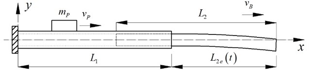
A two-stage Euler-Bernoulli telescopic mechanism is employed to establish dynamic model of the axially moving telescopic mechanism under moving mass, as shown in Fig. 2. Linear densities, bending stiffnesses and lengthes of the constant and telescopic beams are , , , , and , respectively. The time-dependent extended length of the telescopic beam is . The mass weighs and moves at a velocity of relative to the beam. The telescopic beam extends or retracts at a velocity of .
The total kinetic energy contains the transverse vibrational energies of the beams and the mass and the kinetic energy from the telescopic motion of the telescopic beam and the mass. Denoting the time differentiation with a superscripted dot, the total kinetic energy is given as:
where and are the deflections of the constant and telescopic beams, separately, is the equivalent mass of the overlap part in the telescopic beam, is the deflection of the beam at the location of the mass, is the location of the mass and can be expressed as:
where is the initial location of the moving mass, is velocity of the moving mass relative to the ground and:
As the telescopic beam is not tightly connected with the constant beam, the overlap part in the telescopic beam is equivalent to end mass of the constant beam, denoted as:
The total potential energy contains the bending energy of the beams and gravitational energies of the beams and the moving mass. Denoting the differentiation with respect to the spatial coordinate with a prime, the total potential energy is expressed as:
Applying the Hamilton’s principle:
the equations of motion with respect to and can be drawn:
where is the Dirac function.
The kinematic boundary conditions and geometric continuity conditions at the beginning of the constant beam, the end of the constant beam and the end of the telescopic beam are listed as follows:
3. Solutions to the equations
Applying the Galerkin’s method, the deflections of the beams are expressed respectively as:
where is the space dimension, and are respectively the th eigenfunctions of the constant and telescopic beams. The eigenfunctions are time-depedent due to the motion of the telescopic beam. is generalized coordinate. The eigenfunctions are acquired by substituting Eq. (9) to Eq. (8), given as:
where:
where and are eigenvalues of the eigenfunctions separately, denoted as:
where is the natural th frequency of the telescopic beams.
Fig. 2Two-stage telescopic mechanism under moving mass
Substituting Eq. (9) to the Eq. (7), multiplying the first equation by and second equation by in Eq. (7) respectively, integrating them from 0 to and then summing them up, the discretized equations of motion for the telescopic mechanism can be obtained:
where is bending stiffness matrix, is damping matrix, is mass matrix. The entries in the matrixes are given by:
where 1 represents the mass is on the constant beam and 2 on the telescopic beam:
As is shown in the coefficient matrixes, additional stiffness and damping come into being due to the time-dependent feature of the eigenfunctions. The solutions to the equations of motion can be obtained by employing the average acceleration method of the Newmark-.
4. Numerical results
The dynamic responses of the end for the telescopic mechanism of the truss structure bridge inspection vehicle XCMG QJS20A are presented in the numerical examples. The results are analyzed to acquire the influence of moving-mass on the dynamic responses of the telescopic mechanism and explore appropriate mass-moving strategy to avoid large vibration. Specific properties of the telescopic beams are as follows: 10.7 m, 10.7 m, 85 kg/m, 46 kg/m, 35 MPa, 35 MPa. Total length of the telescopic beams when fully extended is limited to 20 m. The weight of the mass is 400 kg according to the maximum static end load. The magnitude of beam-telescoping velocity is set 0.5 m/s and mass-moving velocity 1.5 m/s.
The conditions when the mass is on the constant beam (MOCB) to reach a position in the constant beam and when the mass is on the telescopic beam (MOTB) to reach a position in the telescopic beam are simulated. Nevertheless, the conditions when the mass should cross the constant beam to the telescopic or reverse are not taken into consideration. This is because the processes can be regarded as combinations of the mass moving on the constant beam and on the telescopic beam. To clarify, the simulated conditions are listed in Table 1, in which is the destination of the mass, PFM and PBM present the location is in front of the mass and behind the mass, respectively.
Table 1Parameters in different mass-moving strategies
/ (m/s) | / (m/s) | / m | / m | / m | Corresponding figure | ||
MOCB | PFM | 1.5 | 0 | 5 | 2 | 19 | Fig. 3 |
1.5 | 0.5 | ||||||
1.5 | –0.5 | ||||||
PBM | –1.5 | 0 | 5 | 8 | 19 | Fig. 4 | |
–1.5 | 0.5 | ||||||
–1.5 | –0.5 | ||||||
MOTB | PFM | 1.5 | 0 | 13.7 | 10.7 | 17 | Fig. 5 |
1.5 | 0.5 | ||||||
1.5 | –0.5 | ||||||
0 | 0.5 | ||||||
PBM | –1.5 | 0 | 15.5 | 18.5 | 18.5 | Fig. 6 | |
–1.5 | 0.5 | ||||||
–1.5 | –0.5 | ||||||
0 | –0.5 |
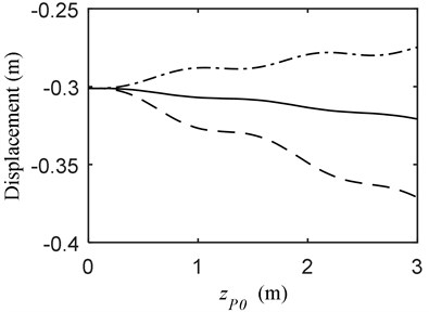
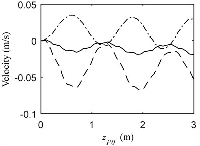
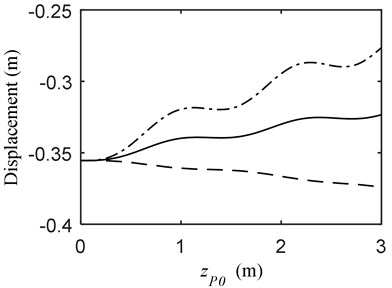
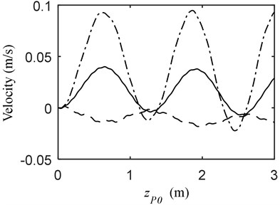
Fig. 3 depicts the vibrational displacement and velocity at the end of the telescopic beam when the mass moves on the constant beam to reach a position 3 m in front. As can be seen, the vibration when the mass as well as the telescopic beam moves forward is stronger than those in the other two conditions. On the other hand, the displacements of the beams tend to increase at 0 m/s and 0.5 m/s; nevertheless, that at –0.5 m/s when the beam moves in the opposite direction to the mass tends to decrease.
The dynamics of the telescopic beam when the mass moves on the constant beam to reach a point 3 m behind are displayed in Fig. 4. The vibration of the beams when the mass and the telescopic beam all moves backward is significantly larger than the other two. Besides, the displacements of the beams tend to increase at 0 m/s and –0.5 m/s; conversely, that at 0.5 m/s when the beam moves in opposite direction to the mass tends to decrease.
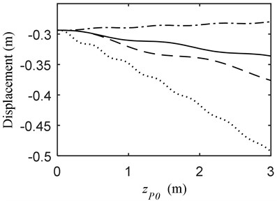
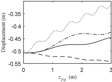
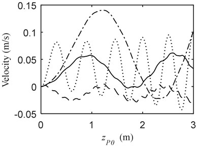
Fig. 5 indicates the dynamic responses of the telescopic beams when the mass moves on the telescopic beam to reach 3 m in front. Similar to that in Fig. 3, the vibration when the mass and the beam move forward synchronously is much heavier than those in the other conditions. The vibration when the mass moves in opposite direction to the telescopic beam is the smallest. However, the working efficiency is consequently reduced. The displacement at 0 m/s increases remarkablely faster than those in the other conditions; moreover, the working efficiency is relatively low. Further, the displacement has a tendency to increase when the beam retracts and those in the other conditions reversely decrease.
Fig. 3Vibration when MOCB and PFM a) displacement, b) velocity; (—) vP= 1.5 m/s, vB= 0 m/s (---) vP= 1.5 m/s, vB= 0.5 m/s (-·-) vP= 1.5 m/s, vB= –0.5 m/s
a)
b)
Fig. 4Vibration when MOCB and PBM a) displacement, b) velocity; (—) vP= –1.5 m/s, vB= 0 m/s (---) vP= –1.5 m/s, vB= 0.5 m/s (-·-) vP= –1.5 m/s, vB= –0.5 m/s
a)
b)
Fig. 5Vibration when MOTB and PFM a) displacement, b) velocity; (—) vP= 1.5 m/s, vB= 0 m/s (---) vP= 1.5 m/s, vB= 0.5 m/s (-·-) vP= 1.5 m/s, vB= –0.5 m/s (···) vP= 0 m/s, vB= 0.5 m/s
a)
b)
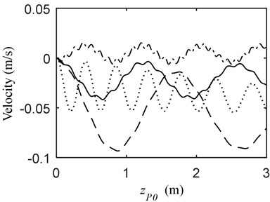
Fig. 6 presents the dynamics of the telescopic beams when the mass moves on the telescopic beam to reach the point 3 m behind. The strongest vibration of the beam occurs in the condition of the mass and the telescopic beam all moving backward. Additionally, the telescopic beam extending in opposite direction to the beam produces the minimum vibration. Nevertheless, different from the other three conditions, the displacement increases in the process.
Fig. 6Vibration when MOTB and PBM a) displacement, b) velocity; (—) vP= –1.5 m/s, vB= 0 m/s (---) vP= –1.5 m/s, vB= 0.5 m/s (-·-) vP= –1.5 m/s, vB= –0.5 m/s (···) vP= 0 m/s, vB= –0.5 m/s
a)
b)
5. Conclusions
Dynamic responses of a two-stage telescopic mechanism for truss structure bridge inspection vehicle under moving mass are studied. The telescopic mechanism is assumed to be telescopic beams within the Euler-Bernoulli theory. The equations of motion are obtained using the Hamilton’s principle and discretized using the Galerkin’s method. The time-dependent eigenfunctions of the beams are derived by substituting the discretized equations to the boundary conditions. The discretized equations are solved using the Newmark- method. In the numerical results, the dynamic resoponses of the telescopic mechanism in different conditions are presented to seek for appropriate mass-moving strategy to avoid strong vibration.
It can be concluded that the conditions when the mass moves synchronously with the telescopic mechanism will not always lead to larger vibration compared with those when they don’t move synchronously. What’s more, the vibration is the smallest when the mass moves on the telescopic beam in opposite direction. On the other hand, the mass’s moving in the direction of the telescopic beam will bring about stronger vibration.
The results can be better understandings of the behaviors for the telescopic mechanism of the truss structure inspection vehicle. Besides, these can also be guides for the maintenance staff in selecting mass-moving strategy to avoid large vibration.
References
-
Öz H. R., Pakdemiorli M. Vibrations of an axially moving beam with time-dependent velocity. Journal of Sound and Vibration, Vol. 227, Issue 2, 1999, p. 239-257.
-
Chen L. Q., Yang X. D., Cheng C. J. Dynamic stability of an axially accelerating viscoelastic beam. European Journal of Mechanics A/Solid, Vol. 23, Issue 4, 2004, p. 659-666.
-
Chen L. Q., Zhao W. J. A conserved quantity and the stability of axially moving nonlinear beams. Journal of Sound and Vibration, Vol. 286, Issue 3, 2005, p. 663-668.
-
Usik L., Hyungmi O. Dynamics of an axially moving viscoelastic beam subject to axial tension. International Journal of Solids and Structures, Vol. 42, Issue 8, 2005, p. 2381-2398.
-
Piovana M. T., Sampaiob R. Vibrations of axially moving flexible beams made of functionally graded materials. Thin-Walled Structures, Vol. 46, Issue 16, 2008, p. 112-121.
-
Wang L. H., Hu Z. D., Zhong Z., et al. Hamiltonian dynamic analysis of an axially translating beam featuring time-variant velocity. Acta Mechanica, Vol. 206, Issues 3-4, 2009, p. 149-161.
-
Liu D., Xu W., Xu Y. Dynamic responses of axially moving viscoelastic beam under a randomly disordered periodic excitation. Journal of Sound and Vibration, Vol. 331, Issue 17, 2012, p. 4044-4056.
-
Mergen H. G., Marco A. Parametric stability and bifurcations of axially moving viscoelastic beams with time-dependent axial speed. Mechanics Based Design of Structures and Machine, Vol. 41, Issue 3, 2013, p. 359-381.
-
Park S., Yoo H. H., Chung J. Eulerian and Lagrangian descriptions for the vibration analysis of a deploying beam. Journal of Mechanical Science and Technology, Vol. 27, Issue 9, 2013, p. 2637-2643.
-
Posiadala B., Cekus D. Discrete model of vibration of truck crane telescopic boom with consideration of the hydraulic cylinder of crane radius change in the rotary plane. Automation in Construction, Vol. 17, Issue 3, 2008, p. 245-250.
-
Cekus D., Posiadala B. Vibration model and analysis of three-member telescopic boom with hydraulic cylinder for its radius change. International Journal of Bifurcation and Chaos, Vol. 21, Issue 10, 2011, p. 2883-2892.
-
Zimmert N., Pertsch A., Sawodny O. 2-DOF control of a fire-rescue turntable ladder. IEEE Transactions on Control Systems Technology, Vol. 20, Issue 2, 2012, p. 438-452.
-
Barthels P., Wauer J. Non-smooth and time-varying systems of geometrically nonlinear beams. Journal of Sound and Vibration, Vol. 315, 2008, p. 455-466.
-
Zhang W., Sun L., Yang X. D., et al. Nonlinear dynamic behaviors of a deploying-and-retreating wing with varying velocity. Journal of Sound and Vibration, Vol. 332, Issue 25, 2013, p. 6785-6797.
-
Raftoyiannis I. G., Michaltsos G. T. Dynamic behavior of telescopic cranes boom. International Journal of Structural Stability and Dynamics, Vol. 13, Issue 1, 2013, p. 1350010.
-
Duan Y. Ch., Wang J. P., Wang J. Q. Theoretical and experimental study on the transverse vibration properties of an axially moving nested cantilever beam. Journal of Sound and Vibration, Vol. 333, Issue 13, 2014, p. 2885-2897.
About this article

This research was supported by the Program for Changjiang Scholars and Innovative Research Team in University (Grant No. IRT1292) and Project Funded by the Priority Academic Program Development of Jiangsu Higher Education Institutions. The authors would like to thank the editors, associate editors and anonymous reviewers for their constructive comments.
