Abstract
To compute vibration impact coefficient at each part of the long-span bridge more accurately, this paper proposed a computational method based on vehicle-bridge coupling vibration. Firstly, the general equations of vehicle-bridge coupling vibration were derived based on the standard fatigue vehicle and multi-scale model of bridges. Secondly, the corresponding program of vehicle-bridge coupling vibration was designed. Thirdly, the computational method of vibration impact coefficient for the long-span bridge was introduced and obtained. The proposed computation method of vibration impact coefficient based on vehicle-bridge coupling vibration was finally verified by the corresponding experiment. They were consistent with each other, and the computational method was reliable and can be used to analyze the bridge. Based on the verified method, a lot of influence factors on vibration impact coefficient were analyzed. As a result, we can obtain a bridge with the smallest vibration impact coefficient. Finally, the remaining life of bridges was computed and evaluated based on the smallest vibration impact coefficient.
1. Introduction
To meet people’s demand, there are more and more long-span bridges in the world. However, with the increasing demand on the long-span bridge, the bridge designers have to face the contradiction between bridge span and self-weight. Due to its large self-weight, the traditional concrete bridge can't meet the requirements of the long-span bridge. The bridges with an orthotropic steel bridge deck can solve this contradiction [1-3].
Vehicle is an important load that bridge structure needs to bear. When a vehicle is running on the bridge, it will cause vibration impact effect on the bridge due to the shake of the vehicle and the unevenness of the bridge, and such vibration impact effect is often larger than that of a stationary vehicle on the bridge. Therefore, it is of great importance to take into account the influence of vibration impact on bridge design. For the long-span bridge, vibration impact effect on the sensitive parts of bridges can't be ignored. There are different computation formulas for vibration impact coefficient of bridges in the world. However, the dynamic loads of motion vehicles are always regarded as the static loads during computation, and the vehicle-bridge coupling vibration is not considered. In addition, for the long-span bridge, the stress history at each fatigue part is different in the same cross section [4]. As the complex vehicle-bridge coupling vibration is not considered, the published regulations can't be used to accurately compute vibration impact coefficient of bridges. Moreover, vibration impact coefficient of the bridge directly decides the design loads of and the service situation. Therefore, it is of great significance to accurately compute vibration impact coefficient of bridges.
To more accurately compute vibration impact coefficient at each part of the long-span steel bridge when the vehicle is running on it, this paper analyzed the vehicle-bridge coupling vibration based on multi-scale model. Then, the computational results were compared with the experimental results to verify the reliability. They were consistent with each other, and the computational method was reliable. Based on the verified method, a lot of influence factors of vibration impact coefficient were analyzed. As a result, we can obtain a bridge with the smallest vibration impact coefficient. Finally, the remaining life of bridges was also computed and evaluated based on the smallest vibration impact coefficient.
2. Theories
2.1. Standard fatigue vehicle
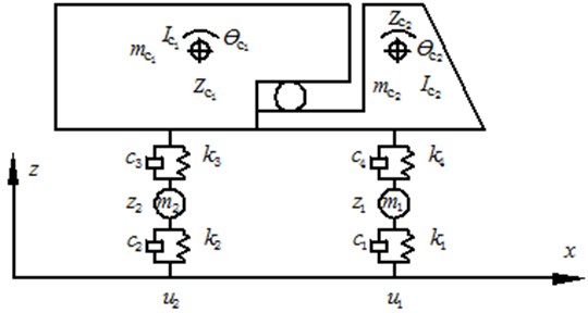
There are a lot of requirements for standard fatigue vehicle models of a highway bridge in the world. Truck vehicle will bring a more serious influence on the bridge because of its large mass. As a result, it is taken as the standard fatigue vehicle model in this paper, as shown in Fig. 1 [5]. The head and trailer are regarded as two rigid bodies, and two axles of the vehicle are composed of mass block and spring-damping system. There are a lot of degrees of freedom in the fatigue vehicle model. Based on the generalized virtual work principle, the differential equation can be obtained as follows:
where , and are the mass, damping and stiffness matrix of the vehicle, respectively. , and are the generalized displacement, speed and acceleration vector. is column vector of gravity. is the columnvector of interaction between vehicle tyres and the bridge surface.
Fig. 1Diagram of a standard fatigue vehicle model
2.2. Vibration equation and multi-scale model of bridges
Generally, a bridge is a structure with multiple degrees of freedom and its vibration equation can be simplified as follow:
where , and are the mass, damping and stiffness matrix of the bridge, respectively. is vector of vehicle-bridge coupling effect. , and are the displacement, speed and acceleration vectors of the bridge, respectively.
In this paper, the program which is used to solve vibration of bridge structure is obtained based on Wilson- method.
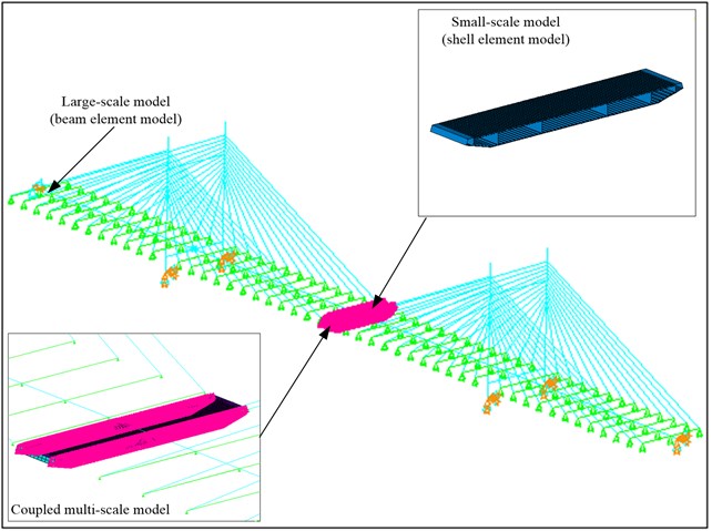
As the long-span bridge has a complex structure, it will be time-consuming to build a refined model of the bridge, and the computational process also requires too high for computers due to the enormous data. If an equivalent simplification analysis is carried out on the bridge, the computational efficiency will be obviously improved, but it will be very difficult to guarantee the computational accuracy. Researchers only pay attention to the stress performance of some key parts instead of all the structure when they analyze the long-span bridge. Therefore, the refined model can be carried out on the concerned parts, and the large scale model can be carried out on the other parts. Two different scale models are coupled by constraint equations at the interface, and then the finite element model of the long-span bridge with a mixed scale is obtained. As a result, the computational efficiency and the accuracy are improved simultaneously [6].
2.3. Simulation of evenness for the bridge surface
The unevenness of the bridge surface will generate excitations on moving vehicles, and change the vibration state of the vehicles, which leads to the random change of wheel pressure loads. Such an influence can’t be ignored in the vehicle-bridge coupling vibration, so surface unevenness should be taken into account in the analysis of vehicle-bridge coupling vibration. Generally, the bridge surface evenness should meet Gauss random distribution [7]. Its shape function can be simulated by the random process, and its expression is shown in the following:
where is the amplitude of cosine function. is the cut-off frequency. is the initial phase angle in [0, 2]. is the sum of the uneven points. is energy power spectral density function, which can be described as spatial frequency function of road surface roughness in [, ] [8], as follows:
In the equation, is the relevant coefficient of the bridge surface and its values are obtained according to Table 1.
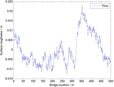
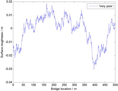
The unevenness of the bridge surface is simulated by the mentioned method, and it is divided into five levels including “very good”, “good”, “general”, “poor” and “very poor”, as shown in Table 1.
Table 1Levels of bridge surface evenness
No. | Bridge surface level | / (m2/(m/cycle)) |
1 | Very good | 0.24×10⁻⁶ |
2 | Good | 0.24×10⁻⁶ 1×10⁻⁶ |
3 | General | 1×10⁻⁶ 4×10⁻⁶ |
4 | Poor | 4×10⁻⁶ 16×10-6 |
5 | Very poor | 16×10-6 |
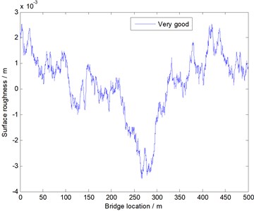
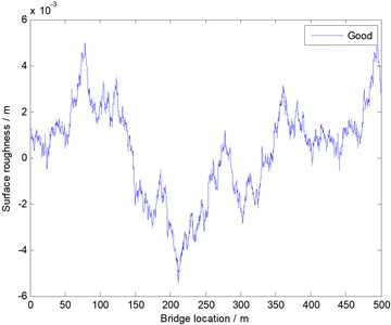
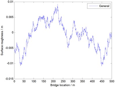
In this paper, by using the method and formulas described in the above, and through programming and computation based on MATLAB, the uneven samples of the bridge surface at all levels are obtained, as shown in Fig. 2. And the sample will be used to analyze the following simulation of the vehicle-bridge coupling vibration. The sample of the unevenness was used to describe five kinds of bridge surfaces as shown Table 1. It can be seen from Fig. 2 that roughness between five kinds of bridge surfaces is very different.
2.4. Numerical analysis method of vehicle-bridge coupling vibration
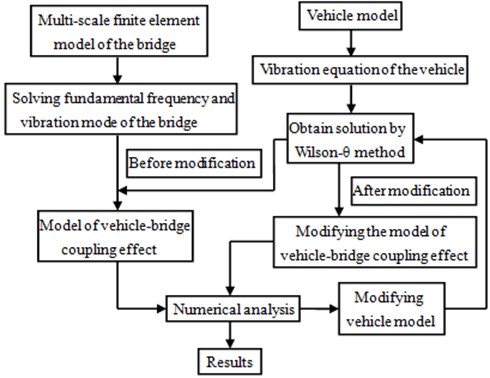
A bridge has its own natural vibration characteristics and equations when no vehicle is running on it. And a vehicle running on a rigid structure also has its natural vibration equations. When a vehicle is running on a bridge, however, the mutual vibration will affect the vibration characteristics of both parties. Therefore, how to solve the respective vibration equations of the vehicle and the bridge is a challenge. If we suppose that when the vehicle is running, the contact points between the wheel and the bridge surface is inseparable, then there will be a joint point between the vibration equations of two systems. By using this inseparable joint point, the respective vibration equations of the bridge and the vehicle at any time can be solved, thus the respective dynamic characteristics of the vehicle and the bridge can be obtained. As a result, the final equations of vehicle-bridge coupling vibration can be obtained. In this paper, the corresponding program of vehicle-bridge coupling vibration is obtained based on MATLAB and ANSYS software. The detailed analysis process is shown in Fig. 3.
Fig. 2Evenness curves of five kinds of bridge surfaces
The vehicle model used in this paper is the fatigue vehicle model recommended by AASHTO Standard, and it is also a full vehicle model. The vehicle head and trailer in the upper part of the vehicle are regarded as two rigid bodies, and two axles are composed of the mass and the spring-damping system. The mass, damping and other properties of the fatigue vehicle can be known through referring to AASHTO Standard, and the vibration control equations of the fatigue vehicle that is adopted in this paper is shown in Eq. (3).
Fig. 3Analysis process of vehicle-bridge coupling vibration
3. The computational method of vibration impact coefficient for the long-span bridge
3.1. Vibration impact coefficient
When a vehicle is running on a bridge at a certain speed, the bridge will have vibration. Therefore, the internal force at each part of the bridge will be enlarged. This vibration effect is called impact effect. During designing a bridge, to consider the dynamic impact effect of vehicle-bridge coupling vibration, the static loads of the vehicle are generally multiplied by a dynamic amplification factor (1), where is vibration impact coefficient as follows:
where is the maximum value of dynamic effect, is the maximum value of static effect. They can be obtained from the vibration acceleration.
There are a lot of bridges in the world and they have different structures. As a result, a convenient and accurate method is necessary to compute vibration impact coefficient of each bridge. In order to solve this question, the computational method based on vehicle-bridge coupling vibration is proposed in this paper.
3.2. The computational method of vibration impact coefficient based on vehicle-bridge coupling
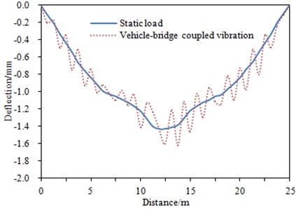
A running vehicle’s dynamic load effect on the bridge structure is larger (sometimes even two or more times larger) than the corresponding static loads. Vehicle loads will generate unequal impacts on different parts of the bridge. Therefore, in the vehicle-bridge coupling vibration analysis, considering the dynamic impact of the vehicle is of great significance to the design and safe operation of the bridge. The impact of running vehicles on the bridge is further studied with the help of the program developed by our lab. By regarding the general bridge surface in Fig. 2 as the standard, an equivalent gravity (60 kN) is applied to a 16 m-span bridge as the uniformly distributed static loads, in order to compute the impact of the bridge span on the middle and lower deflections. Then, by using the vehicle-bridge coupling vibration program developed in this paper as well as regarding the running vehicle as the vibration excitation, the impact of the bridge span on the middle and lower deflections is computed. The final results are shown in Fig. 4, and the step length in the computational process will directly affect the points in the figure. According to Fig. 4, the dynamic load effect generated from the vehicle-bridge coupling vibration will lead to higher fluctuation of the displacement.
Fig. 4The dynamic response of the long-span bridge
3.3. Application of vehicle-bridge coupling vibration
The traditional estimation of the remaining life for the bridge only considers the dynamic amplification effect of the vehicle loads based on vibration impact coefficient. The corresponding vibration impact coefficient is computed by using the simple formulas without considering the coupling between the vehicle and the bridge. Moreover, the dynamic effects at each part of the long-span bridge are not uniform in actual situation due to the large dimensions and complex structure. Therefore, a more accurately method is needed to consider the influence of vehicle-bridge coupling vibration on the remaining life of the bridge.
With the proposed vehicle-bridge coupling vibration program based on multi-scale model of the long-span bridge, the influence factors including vehicle model, bridge surface, vehicle speed, vehicle mass and traffic capacity can be taken into account. And stress history of each fatigue part as well as the dynamic amplification effect of the vehicle loads on it can be obtained more accurately. After taking into account the effect of vehicle-bridge coupling vibration, the remaining life of the steel bridge can be estimated by fracture mechanics [9, 10].
4. Application of the computational method in engineering
4.1. Multi-scale finite element model of double pylon cable-stayed bridge
In this paper, analysis is carried out by taking a double pylon cable-stayed bridge as an example. This bridge is a river-cross highway cable-stayed bridge, with the span of 150 m+200 m+150 m and bilateral eight lanes. The main bridge is orthotropic steel bridge deck slab, and the main pylon is pre-stressed reinforced concrete structure. The cable-stayed bridge is double inhaul cable semi-floating structure. The multi-scale finite element model of the bridge was built by using ANSYS, as shown in Fig. 5. The segments with small-scale were selected based on the published results of similar bridges. In this paper, the mid-span of the bridge was selected as the most serious part of the structure which has the minimum remaining life. Based on the consideration of the safety for the entire structure, the remaining life of this part will determine the remaining life of the whole bridge. The refined models are built for the small-scale segments by using Shell 63 elements, and the models of the other segments were built by using Beam188 elements with large-scale. The material property of the model is steel, so the elastic model is 210 GPa, the density is 7800 kg/m3 and the Poisson’s ratio is 0.3. The models of two scales are connected at their interfaces by building constraint equations, and fixed constraint is applied to the bottom of the main girder. As a result, the multi-scale finite element model of double pylon cable-stayed bridge can be obtained.
Fig. 5Multi-scale finite element model of double pylon cable-stayed bridge
4.2. Computation and verification of vibration impact coefficient
Based on the mentioned vehicle-bridge coupling vibration program, the change curve of vibration impact coefficient under different vehicle speeds and bridge surfaces can be obtained. Furthermore, influences brought by vehicles on the remaining life of bridges structures can be researched.
In the vehicle-bridge coupling model, the vehicle was running on the bridge at the speed of 10 km/h-142 km/h. The increment of driving speeds is 4 km/h. A general road surface in Fig. 2 was taken as the bridge surface. At this moment, the damping of the bridge structure was 0.2. Vehicles running on the bridge will inevitably cause the vibration of the bridge, and the vibration acceleration responses of the bridge under different vehicle speeds can be obtained using the finite element model and the coupling vibration program. Fig. 6 showed the vibration acceleration of a certain point in the middle of the bridge when the vehicle speeds are 18 km/h and 118 km/h, respectively. According to two figures, when the vehicle was running on the bridge at a constant speed, the strong vibration was not transmitted to the middle of the bridge, thus the vibration acceleration was small. When the vehicle moved away from the bridge, the vibration acceleration has changed into small due to the effect of the bridge’s own damping. In addition, it can be seen from the comparison of two figures that the vibration acceleration of the bridge when the vehicle is at the speed of 118 km/h was significantly higher than that of 18 km/h. And the reason was that a larger vehicle speed can result in a stronger impact on the bridge. Finally, based on the bridge vibration acceleration, vibration impact coefficient of the vehicle to the bridge under different speeds can be obtained, as shown in Fig. 7.
Fig. 6Vibration acceleration response of bridges
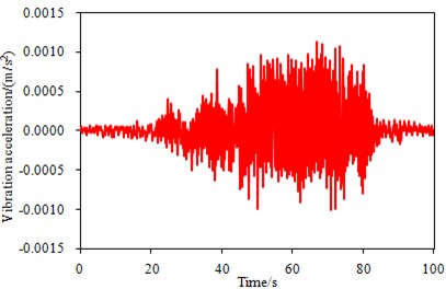
a) 18 km/h
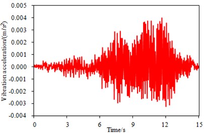
b) 118 km/h
Fig. 7Change curve of vibration impact coefficient under different vehicle speeds
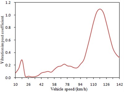
It is shown in Fig. 7 that vibration impact coefficient of the bridge has a large fluctuation with changes of vehicle speeds. When vehicle speeds are 18 km/h and 118 km/h, respectively, vibration impact coefficient has two obvious peaks. This is mainly because the vehicle is coupled with the bridge when it is running at these speeds, and the impact effect of the vehicle to the bridge is strengthened. Therefore, the bridge will be destroyed most seriously when the vehicle is running at 18 km/h or 118 km/h. Besides, the impact of 118 km/h on the bridge is significantly larger than that of 18 km/h, which further verifies the results in Fig. 6.
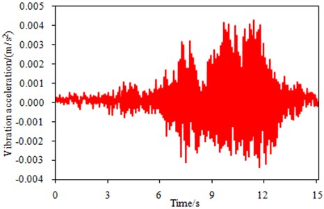
The mentioned analysis is only based on simulation. However, vehicle-bridge coupling model is very complex, and it is necessary to conduct the experimental verification. The experiment was conducted in winter, as shown in Fig. 8. The experimental results obtained for a vehicle running on a bridge were used for this research. The experimental schematic was shown in Fig. 9. The main segment bridge is 200 m long. The Young’s modulus of material is 2.1e9 N/m2. The mass density is 2300 kg/m3, and Poisson ratio is 0.3. A leading segment bridge for the vehicle was used to pick up vehicle speeds and another segment bridge at the other end for receiving the vehicle after it exited from the main segment bridge. Acceleration sensor was mounted at the bottom of the main segment bridge to measure the dynamic response of the bridge. An 8-channel dynamic testing and analysis system were used for data collection and analysis in the experiment. The sampling frequency was 2000 Hz. The recorded length of each test lasted for 15 s, and the test for each speed was repeated three times. During the experiment, the vehicle was running on the bridge surface at the speed of 10 km/h-142 km/h, and the increment of driving speeds is 4 km/h. A total of 34 sets of data were collected. Mass of the vehicle is 6,000 kg. After the experiment, the averaging treatment was conducted to the bridge vibration accelerations obtained by three times experiment under each speeds. Finally, we can obtain the bridge vibration acceleration which was close to the actual value. The bridge vibration acceleration when the vehicle was at speed of 118 km/h was shown in Fig. 10. Through comparing Fig. 10 and Fig. 6, it is clear that the computational and experimental values of the bridge vibration acceleration in the same location are very close, and that their change trends during the measurement are basically identical. This shows that the numerical model in the paper is reliable. Then, vibration acceleration was substituted into the mentioned equations to obtain vibration impact coefficient. As a result, the experimental results were compared with the computational value of vibration impact coefficient, as shown in Fig. 11.
Fig. 8The experimental site of vehicle-bridge coupling
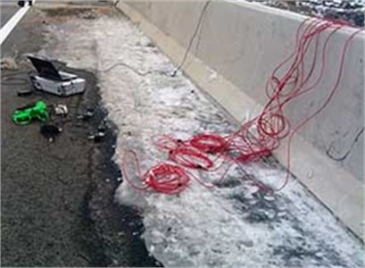
Fig. 9The experimental diagram of vibration impact coefficient for bridges
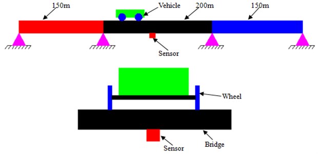
Fig. 10Experimental vibration acceleration response of bridges at speed of 118 km/h
It is shown in Fig. 11 that the experimental results are more than the computational values, which is mainly because only effects of the vehicle to bridges are taken into account during simulation. However, the bridge will also be influenced by air to a certain extent in the practical process. The influence brought by air will be ignored when the vehicle is running on the bridge. Therefore, the final experimental results are only slightly higher than the computational values and they do not much differ from each other. It is shown that the simulation model is reliable and it can be used to predict vibration impact coefficient of bridges.
Fig. 11Comparison of vibration impact coefficient between experiment and simulation
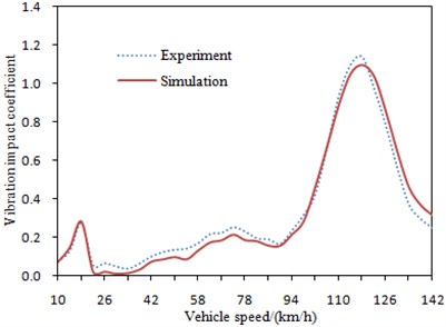
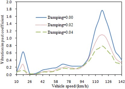
Fig. 12Change curve of vibration impact coefficient under different damping
5. Analysis of influence factors for vibration impact coefficient
A bridge is similar to a simple-support structure, so that its dynamic response will surely be influenced by a lot of factors. Therefore, it is necessary to comprehensively research the changes of vibration impact coefficient from different factors to design a bridge structure with better performance when a vehicle is running on the bridge.
5.1. Damping of bridges
Damping of a bridge structure is an important factor which can influence dynamic response of the bridge. In general, the dynamic response is correspondingly big when the bridge structure damping is small, and the dynamic response is small when the bridge structure damping is big. The bridge structure damping is very difficult to be determined and it can be only obtained through experiment in general. It is shown by many experiments and researches that the damping of a concrete bridge is generally 0.02-0.06. In order to research influences brought by the bridge damping to vibration impact coefficient, bridge damping was respectively set to be 0.0, 0.02 and 0.04 to compute vibration impact coefficient, and the corresponding results were shown in Fig. 12.
It is shown in Fig. 12 that the change tendency of vibration impact coefficient is same under different damping. Vibration impact coefficient decreases with increasing of damping. Bridge damping will bring an obvious influence to vibration impact coefficient in resonance area. The vehicle speed at bridge resonance is not influenced by damping. There are two obvious resonance peaks under different damping. The first resonance speed is 18 km/h and the second resonance speed is 118 km/h. Although bridge damping will not influence the vehicle speed of resonance, but it will influence the value of vibration impact coefficient. The peak of vibration impact coefficient with a big damping is obviously smaller than the peak with a small damping. This is mainly because damping can reduce vibration and vehicle impact to the bridge.
5.2. Mass of vehicles
In the vehicle-bridge coupling system, vibration impact coefficient may much differ due to that the different vehicles have the different masses. In order to research influences brought by this factor to vibration impact coefficient, vibration impact coefficient of four kinds of vehicles with different masses were computed at the speed of 10 km/h-142 km/h, and the corresponding results were shown in Fig. 13.
It is shown in Fig. 13 that the change tendency of vibration impact coefficient is same under different vehicle mass. Vibration impact coefficient of truck vehicle is the maximum in resonance area, and it is mainly because truck vehicle has a maximum mass and the coupling effect will be strongest. As a result, truck vehicle is taken as the vehicle model in the other analyzes. In order words, if the bridge is not damaged under truck vehicle, the other vehicles will not bring any serious damage to the bridge.
Fig. 13Change curves of vibration impact coefficient under different vehicle mass
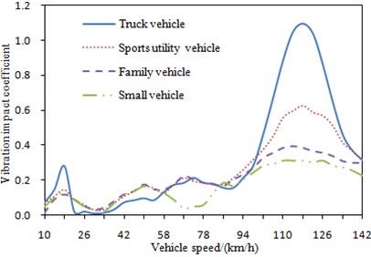
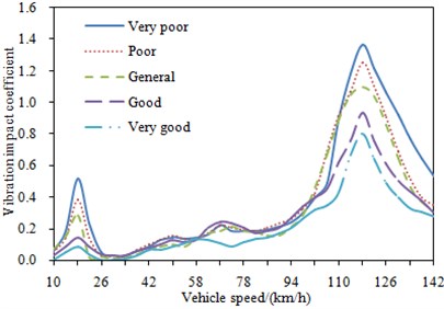
Fig. 14Change curve of vibration impact coefficient under different road surfaces
5.3. Bridge surfaces
As shown in Fig. 2, there were five kinds of bridge surfaces in general. There will be different vibration impact under different bridge surfaces. Therefore, vibration impact coefficient was computed under five kinds of bridge surfaces when the other parameters were unchanged, and the corresponding results were shown in Fig. 14.
It is shown in Fig. 14 that the change tendency of vibration impact coefficient is same under different bridge surfaces. In addition, the poorer bridge surface will bring a bigger vibration impact coefficient, and it is mainly because the interaction coupling between the vehicle and bridges is bigger when bridge surfaces are poorer. Therefore, bridge surfaces shall be well built as much as possible to reduce vibration impact coefficient. However, such method will make a higher cost. As a result, bridge surfaces are always built into a general state, as shown in Fig. 2. Therefore, vibration impact coefficient is mainly researched on a general bridge surface.
5.4. Stiffness of bridges
Changes of stiffness will cause the change of the natural vibration frequency for bridges and then influence dynamic response of bridges. In order to research influences of stiffness on vibration impact coefficient, the stiffness was changed to conduct dynamic analysis of vehicle-bridge coupling system. The elastic modulus of concrete material which was used to build bridges was reduced to 1/2 and 1/4 of the original value, respectively. As a result, the overall stiffness of the bridge was also reduced to 0.5 and 0.25 times of the original value, respectively. During the computation, truck vehicle was taken as the vehicle model. Change curves of vibration impact coefficient under three kinds of stiffness were shown in Fig. 15.
It is shown in Fig. 15 that the change tendency of vibration impact coefficient is same under three kinds of stiffness. In addition, the natural frequency of bridges will be reduced when stiffness reduced. As a result, resonance area of vehicle-bridge coupling system moves forward and it is reflected in Fig. 15.
Fig. 15Change curve of vibration impact coefficient under three kinds of stiffness
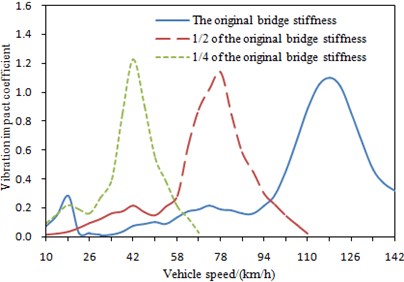
Fig. 16Change curve of vibration impact coefficient under different mass of bridges
5.5. Mass of bridges
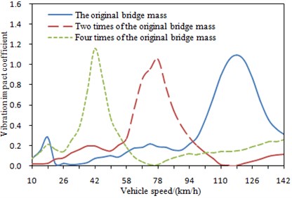
Mass of bridges is also one of factors which can influence vibration impact coefficient. Increase or decrease of mass will directly influence modals of a bridge and thus influence dynamic response of the bridge. In order to observe influences brought by this factor on vibration impact coefficient, mass of bridges was changed into 2, 3 and 4 times of the original mass. Vibration impact coefficient was computed, as shown in Fig. 16.
It is shown in Fig. 16 that the change tendency of vibration impact coefficient is same under different mass of bridges. With increasing of mass, the natural frequency of bridges will be reduced. As a result, resonance area of vehicle-bridge coupling system moves forward.
6. Fatigue fracture computation based on vibration impact coefficient
By using the vehicle-bridge coupling vibration program of the long-span bridge, factors that influence the fatigue life of the bridge, such as the selection of fatigue standard vehicle models, the evenness of bridge surfaces, vehicle speeds, vehicle mass and traffic situation, can be comprehensively considered, and a more accurately vibration impact coefficient for each part can be obtained. After considering the vehicle-bridge coupling vibration, the fatigue life of a steel bridge can be estimated based on the fracture mechanics. Among all the current researches of the fatigue crack propagation process, the most classic one is the crack propagation rate formula [11] as follows, which was proposed based on the linear elastic fracture mechanics by Paris:
where is the crack depth. is the number of stress cycles. and are material constants, and can be measured in experiment. is the amplitude of intensity factor, and can be obtained from the bridge vibration impact coefficient.
By integrating Eq. (9), the number of cyclic loads on the structure when the initial crack depth is expanded to the failure crack depth , and the computation formula for the steel-bridge fatigue crack propagation life is as follows:
wherein, is the initial crack depth, and is the final failure crack depth.
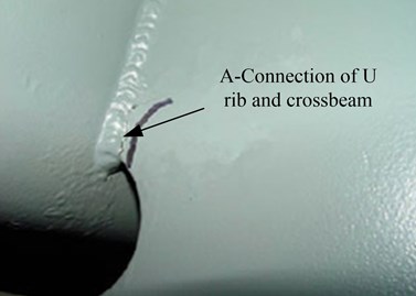
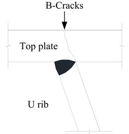
Based on the mentioned method, two common cracks in the orthotropic steel bridge deck slab were studied, as shown in Fig. 17. Crack A where the longitudinal rib and the diaphragm plate were welded and crack B where the top plate and the longitudinal stiffener were welded. Analysis was carried out on the fatigue cracks at A and B to obtain the remaining life at A and B, as shown in Fig. 18.
Fig. 17Positions of two fatigue cracks on the bridge
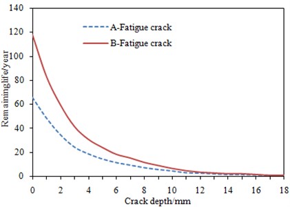
According to the slope of the curve of remaining life in Fig. 18, the propagation rates of the details are slow at the early stage of crack propagation, but the propagation rates will become faster in middle and later stages. The remaining life of the detail at crack A is almost 50 % less than that at crack B, which indicates that the remaining life at different parts in the same cross section of bridges may be also different. And it also reflects the difference of stress concentration degree at each part. The difference between the remaining life at crack A and B reflects the advantages of the method for estimating the remaining life of the long-span bridge by considering the effect of vehicle-bridge coupling vibration, and the proposed computation method can analyze remaining life on each selected detail part.
Fig. 18Remaining life at crack A and B of the double pylon cable-stayed bridge
7. Conclusions
1) The amplification effect of vehicle-bridge coupling on the stress of each detail part can’t be ignored when we conduct dynamic response analysis on the long-span bridge.
2) The proposed computation method of vibration impact coefficient for the long-span bridge can take into account these factors including vehicle-bridge coupling, vehicle model, bridge surface evenness and vehicle speed etc. Moreover, based on the multi-scale finite element model of the bridge, the stress history at each detail part can be randomly selected to carry out analysis. As a result, more accurately results from vibration and fatigue analysis on the bridge can be obtained.
3) The proposed computation method of vibration impact coefficient based on vehicle-bridge coupling vibration is verified by the corresponding experiment. They are consistent with each other, and the computational method is reliable. Based on the verified method, a lot of influence factors on vibration impact coefficient are analyzed. As a result, we can obtain a bridge with the smallest vibration impact coefficient.
4) According to the smallest vibration impact coefficient, the bridge with the relative bigger remaining life can be obtained. The results show that remaining life at each detail part of the bridge is different, when the evenness of the bridge surface deteriorates to “poor” and “very poor”, vibration impact coefficient will increase to a great extent, and the remaining life will reduce to a great extent.
References
-
Tao X. Y., Liu X. G., Zhang Y. L. Study on the stress characteristics of orthotropic steel deck. Steel Construction, Vol. 25, Issue 7, 2010, p. 12-14.
-
Lee S. B. Fatigue failure of welded vertical members of a steel truss bridge. Engineering Failure Analysis, Vol. 3, Issue 2, 1996, p. 103-108.
-
Wong K. Y. Structural identification of Tsing-ma bridge. Transaction of the Hong Kong Institute of Engineers, Vol. 10, Issue 1, 2003, p. 38-47.
-
Li Z. X., Zhou T. Q., Chan T. H. T., et al. Multi-scale numerical analysis on dynamic response and local damage in long-span bridge. Engineering Structures, Vol. 29, Issue 7, 2007, p. 1507-1524.
-
AASHTO LRFD Bridge Design Specification. AASHTO, USA, 1994.
-
Koichi M., Tetsuya I., Toshiharu K. Multi-scale modeling of concrete performance integrated material and structural mechanics. Journal of Advanced Concrete Technology, 2003, p. 91-126.
-
Au F. T. K., Cheng Y. S., Cheng Y. K. Effects of random road surface roughness and long-term deflection of prestressed concrete girder and cable-stayed bridges on impact due to moving vehicles. Computers and Structures, Vol. 79, Issue 8, 2001, p. 853-872.
-
Honda H., Kajikawa Y., Kobori T. Spectra of road surface roughness on bridges. Journal of Structural Division ASCE, Vol. 108, 1982, p. 1956-1966.
-
Cheng J., Zhao S. S. Fracture Mechanics. Science Press, Beijing, 2006, p. 147-154.
-
Zhang A. G., Zhu J. C., Chen M. C. Fatigue, Fracture and Damage. Southwest Jiaotong University Press, Chengdu, 2006.
-
Paris P. C., Gomez M. P., Anderson W. P. A rational analytic theory of fatigue. The Trend in Engineering, Vol. 13, 1961, p. 9-14.
About this article

This project is supported by Fundamental Research Funds for the Central Universities (310821153306) and Postdoctoral Science Foundation of China (2015M572511).
