Abstract
Transverse vibrations of the two dimensional system of pipes are investigated. The model of transverse vibrations of a two dimensional pipe system consisting from beams by taking the inertia of fluid filling the pipes into account is used and the eigenmodes are determined. Then the places of the pipes with small amplitudes of vibrations and with large amplitudes of vibrations for the eigenmodes are determined. After this the places where the amplitudes for several first eigenmodes are large are indicated. In those places it is recommended to perform measurements of transverse vibrations of the pipe system.
1. Introduction
The two dimensional system of pipes is investigated. In the previous paper [1] vibrations of the pipe system in its plane were analyzed. But the experimental investigations indicate that in many cases transverse vibrations of the two dimensional pipe system take place. Thus this paper is devoted to the analysis of transverse vibrations of a pipe system. The model for the analysis of transverse vibrations of a pipe system consisting from two dimensional beams by taking the inertia of fluid filling the pipes into account is used and the eigenmodes are determined.
The places of the pipe with small amplitudes of transverse vibrations and with large amplitudes of transverse vibrations for the eigenmodes are determined. Then the places where the amplitudes of transverse vibrations for several first eigenmodes are large are determined. In those places it is recommended to perform measurements of transverse vibrations of the two dimensional system of pipes.
The model for the analysis of transverse vibrations of a pipe system is proposed on the basis of the results described in [2-4]. Similar problems of dynamics, vibrations and stability are investigated in [5-11].
2. Model for the analysis of transverse vibrations of a pipe system
In the description of the model for the analysis of transverse vibrations of the pipe presented below , and denote the axes of the system of coordinates. The finite element of a two dimensional beam representing the pipe in the plane has three nodal degrees of freedom: the displacement in the direction of the axis denoted as , the rotation about the axis denoted as and the rotation about the y axis denoted as .
The values of , , in the element of a pipe are represented as:
where is the vector of generalized nodal displacements and:
where are the shape functions of the one dimensional finite element of the pipe.
The rotations about the longitudinal axis of the pipe and about the axis perpendicular to and located in the plane are denoted as and . They are related with the displacements in the global directions as:
where:
where is the local coordinate of the finite element of the pipe and:
The following notation is used:
The derivatives of , , are assumed as:
where:
On the basis of the previous notations it is assumed that:
The following notation is used:
The stiffness matrix of the model of a pipe for the analysis of transverse vibrations has the form:
where is the modulus of elasticity of the pipe, is the Poisson’s ratio of the pipe, is the internal radius of the pipe, is the external radius of the pipe and:
The mass matrix of the model of a pipe for the analysis of transverse vibrations has the form:
where is the density of the material of the pipe, is the density of the fluid filling the pipe.
3. Transverse vibrations of a pipe system
The structure consists from two parallel straight pipes both of them having fixed ends (all of the generalized displacements equal to zero) and they are assumed filled with water. The midpoints of both pipes are connected by an empty pipe perpendicular to them. Length of the structure is 2 m and the distance between the two parallel pipes is 0.4 m. The following parameters are assumed: modulus of elasticity of the pipes 6·108 Pa, Poisson’s ratio of the pipes 0.3, density of the material of the pipes 785 kg/m3, density of the fluid filling the two pipes 998 kg/m3, internal radius of the pipes 0.004 m, external radius of the pipes 0.006 m.
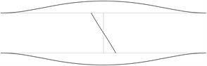
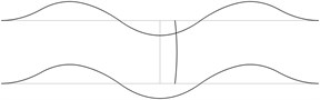
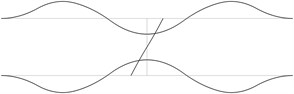
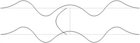
The displacement in the direction of the axis is represented in the normal direction to the pipe in the plane . The first eigenmodes are shown in Fig. 1.
Fig. 1The first eigenmodes of the pipe system: a) the first eigenmode, b) the second eigenmode, …, j) the tenth eigenmode
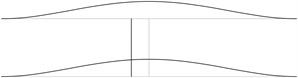
a)
b)
c)
d)
e)
f)
g)
h)
i)
j)
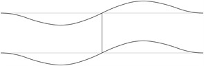
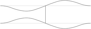
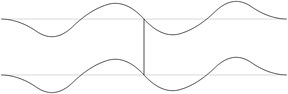
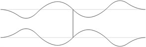
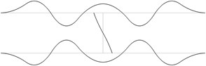
Fig. 2The acceptable places of measurement of transverse vibrations for the first eigenmodes of the pipe system: a) for the first eigenmode, b) for the second eigenmode, …, j) for the tenth eigenmode

a)

b)

c)

d)

e)

f)

g)

h)

i)

j)
In order to perform precise measurements of transverse vibrations of a pipe system the measurements are to be performed not at the nodes of the eigenmodes and preferably at the places with higher amplitudes of vibrations. It is considered that the amplitudes are large when they are greater than half of the maximum amplitude of vibrations for the eigenmode. The places with small amplitudes are denoted by black lines and the places with large amplitudes are denoted by grey lines. The acceptable places of measurement for the first eigenmodes are presented in Fig. 2.
The obtained acceptable places for measurements of transverse vibrations for the first six eigenmodes are presented in Fig. 3.
Fig. 3The acceptable places of measurement of transverse vibrations for the first six eigenmodes of the pipe system

Thus in order to perform successful measurements of the first six eigenmodes of transverse vibrations of the pipe system it is recommended to locate the measurement device in the places of the pipes which are indicated as grey (not black) in the presented figure.
4. Conclusions
The structure consisting from two parallel straight pipes both of them having fixed ends (all of the generalized displacements equal to zero) and filled with water is investigated. The midpoints of both pipes are connected by an empty pipe perpendicular to them. The first eigenmodes of their transverse vibrations are obtained.
In order to perform precise measurements of transverse vibrations of a pipe system the measurements are to be performed not at the nodes of the eigenmodes and preferably at the places with higher amplitudes of transverse vibrations. It is considered that the amplitudes are large when they are greater than half of the maximum amplitude of vibrations for the eigenmode. The acceptable places of location of the measurement device for the first eigenmodes are determined.
Thus the acceptable places for performing the measurements of transverse vibrations for the first several eigenmodes are easily obtained as presented in this paper.
References
-
Sudintas A., Paškevičius P., Spruogis B., Maskeliūnas R. Measurement of vibrations of a pipe system. Journal of Measurements in Engineering, Vol. 1, Issue 2, 2013, p. 101-105.
-
Bathe K. J. Finite Element Procedures in Engineering Analysis. Prentice-Hall, New Jersey, 1982.
-
Zienkiewicz O. C. The Finite Element Method in Engineering Science. Mir, Moscow, 1975.
-
Bolotin V. V. Vibrations in Engineering. Handbook, Vol. 1, Mashinostroienie, Moscow, 1978.
-
Prokofiev A., Makariyants G., Shakhmatov E. Modeling of pipeline vibration under the pressure ripples in the working fluid. 17th International Congress on Sound & Vibration, Cairo, Egypt, 2010, p. 1-8.
-
Yih-Hwang Lin, Yau-Kun Tsai Nonlinear vibrations of Timoshenko pipes conveying fluid. International Journal of Solids and Structures, Vol. 34, Issue 23, 1997, p. 2945-2956.
-
Murphy J. F. Transverse vibration of a simply supported beam with symmetric overhang of arbitrary length. Journal of Testing and Evaluation, Vol. 25, Issue 5, 1997, p. 1-3.
-
Zhang Y. L., Gorman D. G., Reese J. M. Analysis of the vibration of pipes conveying fluid. Proceedings of the Institution of Mechanical Engineers, Part C: Journal of Mechanical Engineering Science, Vol. 213, Issue 8, 1999, p. 849-860.
-
Chellapilla K. R., Simha H. S. Vibrations of fluid-conveying pipes resting on two-parameter foundation. The Open Acoustics Journal, Vol. 1, 2008, p. 24-33.
-
Liu L., Xuan F. Flow-induced vibration analysis of supported pipes conveying pulsating fluid using precise integration method. Mathematical Problems in Engineering, Vol. 2010, p. 1-15.
-
Maalawi K. Y., EL-Sayed H. E. M. Stability optimization of functionally graded pipes conveying fluid. World Academy of Science, Engineering and Technology, Vol. 79, 2011, p. 374-379.
About this article

