Abstract
This paper presents a topology optimization method to design the optimal layout of Constrained Layer Damping (CLD) material in structures subjected to harmonic excitations or stationary random excitations. A finite element model is used to describe the dynamic performances of the CLD structure. Since energy dissipation arises only from the viscoelastic (VEM) layer, the modulus of elasticity of the VEM layer is complex. The complex mode superposition method is employed to calculate the steady-state response of the CLD structure under harmonic excitations. According to Pseudo-Excitation Method (PEM), the vibration analysis of stationary stochastic excitations can be transformed to the analysis of harmonic excitations. The minimization of frequency response at specified one point or several points in structures are selected as optimization objective. The Solid Isotropic Material with Penalization (SIMP) method is adopted to interpolate the CLD material. The sensitivity is derived by means of the adjoint variable method which is more efficient than the direct variable method. The Method of Moving Asymptote (MMA) is used to search the optimal layout of CLD material on structures. Numerical examples are given to illustrate the efficiency and verification of the proposed approach.
1. Introduction
Constrained Layer Damping (CLD) treatment has been regarded as an effective way to suppress structural vibrations and sound radiation. It has been used in some critical structures of many engineering fields including vehicles, airplanes, automobiles, ships. In engineering applications, the full coverage CLD treatments are evidently not practical in purpose due to extra mass and material consumption. Therefore, a partial-coverage treatment is a more attractive approach to fulfill the real CLD treatment requirements. Lall, Asnani and Nakra [1-2] performed more thorough analytical studies for partially covered planar structures. An important finding from these studies was that for suitably chosen parameters, higher values of the modal damping factor may be obtained for a partially covered beam compared to that obtained for a fully covered one under the condition of the same added weight of PCLD treatments. Chen and Huang [3] investigated the damping effects of the CLD treatment of strip type on a cylindrical shell, and discussed the influences of different design parameters and number of strips on vibration response of the shell with CLD treatment. Zheng and Zeng [4] derived the differential equations of motion of a partially covered sandwich cantilever beam employing Hamilton’s principle and evaluated the effects of different physical and geometrical parameters on resonance peaks. Blais et al. [5] calculated the transient time response of impacted beams with a partial CLD treatment through the Laplace transform approach.
A lot of efforts have been carried out to improve the damping performance by means of optimal design of CLD treatments on structures so far. Lumsdaine [6] determined the optimal shape of a constrained damping layer on an elastic beam by means of topology optimization. The optimization objective is to maximize the system loss factor for the first mode of the beam. Moreira and Rodrigues [7] used Modal Strain Energy (MSE) method to optimally locate passive constrained viscoelastic damping layers on structures. The experimental results verified the effectiveness of the proposed optimization approach. Lepoittevin and Kress [8] investigated the effect of segmented CLD on vibration energy dissipation and developed an optimization algorithm using mathematical programming to identify a cuts arrangement that optimized the loss factor. Zheng et al. [9] studied the topology optimization for the layout of CLD in plates to suppress structural vibration and sound radiation. The objective is to minimize structural modal damping ratio using MMA approach. Ansari et al. [10] adopted novel level set method to search the best shapes and locations of the CLD patches on a cantilever plate. The main goal is to maximize structural modal loss factor. It is found that the proposed method can increase structural modal loss factor significantly through the shape change from a square to a circle. Kim [11] investigated the optimal layout of unconstrained layer damping by using topology optimization, Strain Energy Distribution (SED) and the Mode Shape Approach (MSO). It is found that topology optimization usually provides a higher modal loss factor. Chen and Liu [12] proposed a topology optimization method for designing a viscoelastic cellular material. In their study, the effective behavior of viscoelastic materials is derived through the use of a finite element based homogenization method. Only isotropic matrix material was considered. Interesting topological patterns for guiding the viscoelastic cellular material is thus designed. Structural dynamic optimization is often considered as an efficient way to reduce high vibration level subject to external excitation frequencies. The dynamic compliance is also often selected as the objective function of structural dynamic optimization. Structural dynamic optimization reduces the frequency response over the whole structure. Furthermore, the resonance under the excitation force is suppressed and thus the global dynamic performance of structure is improved. Jog [13-14] proposed a method to minimize the amplitude of frequency response through the topology optimization of structure subjected to a periodical loading. Du and Olhoff [15], Nandy and Jog [16] optimized the structure to minimize the dynamic compliance and reduce the radiated sound power from the structure. The advantage of the proposed approach is that minimizing the dynamic compliance can move the natural frequencies away from the driving frequency, thus a reduction in sound radiation power can be achieved. The frequency response is considered as the objective function to improve the structural dynamic performance. Rong et al. [17] developed the Evolutionary Structural Optimization (ESO) method to control the structural dynamic responses in random excitation. Moshrefi-Torbati et al. [18] implemented a genetic algorithm to obtain the non-standard truss geometries that exhibit the reduction in structural dynamic response over a sought frequency range. Zheng et al. [19] studied the optimal placement of the rectangular damping patches to minimize the structural displacement of cylindrical shells through the Genetic Algorithm. Zheng [20] presented a comparison of optimization algorithms for CLD layout to minimize the maximum vibration response of the odd modes, which constituted the dominant acoustic radiation of a simply supported beam. Four different nonlinear optimization methods such as sub-problem approximation method, Sequential Quadratic Programming (SQP), the first-order method and Genetic Algorithm (GA) are used to optimize the CLD locations to minimize the displacement amplitude at the middle beam. Hussein et al. [21] used a genetic algorithm in a similar manner to ‘tune’ the frequency response of one-dimensional waveguides by adjusting the number of layers of alternate materials and their thicknesses. Alvelid et al. [22] proposed a modified gradient of damping materials to mitigate noise and vibration. Dede and Hulbert [23] presented a method for developing new truss-like sandwich structures that exhibit desirable mid-frequency vibratory characteristics. Yoon [24] proposed a topology optimization based on the SIMP method for the frequency response problem where the structure is subject to the wide excitation frequency domain. Shu et al. [25] proposed a level set based structural topology optimization to minimize frequency response. The general objective function is formulated as the frequency response minimizes at the specified points or surfaces with a predefined excitation frequency or a predefined frequency range under the volume constraint. But few researches have been performed on topology optimization of the dynamic response of the CLD structure.
This paper proposes a structural topology optimization to minimize the frequency response of the CLD plates under harmonic excitations or stationary random excitations. A finite element model is developed to describe the dynamic performances of the CLD plate. The complex mode superposition method is employed to calculate the steady-state response of the CLD structure. According to Pseudo-Excitation Method (PEM), the vibration analysis of stationary stochastic excitations can be transformed to the analysis of harmonic excitations. The topology optimization problem is thus formulated and the minimization of frequency response is considered as the objective function to reach an effective vibration suppression with less extra mass of CLD material. The SIMP method is used to interpolate the CLD material. Then, the sensitivity of the objective function to design variables is derived by using the adjoint variable method. The MMA is adopted to search the optimal layout of CLD material on plates. Numerical examples are then given to verify the proposed optimized method.
2. Finite element model
The CLD structure consists of a base plate covered with CLD material. The base plate and the constrained layer are isotropic and linearly elastic and their shear strains are negligible. The VEM layer dissipates the vibrational energy. The modulus of elasticity of the VEM layer is complex, such that , where is the loss factor and .
Fig. 1 is a schematic drawing of an element in finite element model of the CLD plate. The element is a four-noded rectangular element whose dimensions are 2×2, while the thicknesses of the base layer, the VEM layer and constrained layer are , and , respectively.
Fig. 1The schematic drawing of an element in finite element model of CLD plate
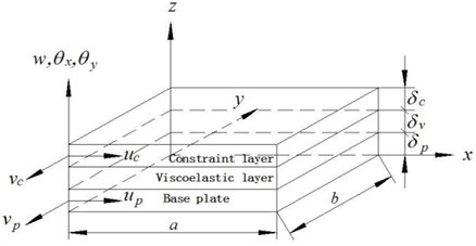
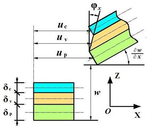
The plate/CLD elements here are two-dimensional elements bounded by four nodal points. Each node has seven degrees of freedom to describe the longitudinal displacements of the constrained layer, , , the longitudinal displacements of the base plate, , , the transverse deflection and the slopes of the deflection line, , . Accordingly, each node of the four-noded element has seven degrees of freedom corresponding to the five displacement components: . The geometry and deformation of the plate with CLD treatment is as shown in Fig. 2. The rotation degrees of freedom can be expressed in terms of the gradients of lateral deflection, such that:
The strain-displacement relations between layers are as follows:
where is the distance from the plate’s neutral surface to the CL’s central surface.
The spatial distributions of the longitudinal displacements , , , as well as the transverse deflection over any element of the plate with CLD treatment can be given by:
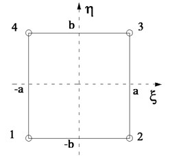
where the constants are determined in terms of the twenty eight components of the node deflection vector of the element which is bonded by the nodes 1, 2, 3, 4 as shown in Fig. 1. The node deflection vector is given by:
where:
Fig. 2Geometry and deformation of the plate with CLD treatment
Therefore, the deflection at any location inside the element can be obtained from:
where , , , , , and are the spatial interpolating vectors corresponding to , , , , , and respectively.
The total kinetic energy of the composite plate is the sum of all kinetic energies from the base plate, the VEM layer and the constrained layer:
For the th layer in the th element:
where is the mass matrix of the th element of the th layer.
Similarly, the total potential energy of the composite plate is the sum of all potential energies from the base plate, the VEM layer and the constrained layer:
For the base plate and constrained layer in the th element:
where is the stiffness matrix of the eth element of the th layer.
For the VEM layer in the th element:
where and are the stiffness matrices of the eth element of the VEM layer. and are respectively the rotational component of the node along the axis and axis. is the shear modulus.
Assembly of the mass and stiffness matrices yields the global mass and stiffness matrices. The global mass and stiffness matrices as well as the equation of the entire plate/CLD system are given as follows:
where and are the global mass and stiffness matrices respectively. and are the real and imaginary parts of the stiffness matrix. Also, is external disturbance force vector of the plate/CLD system. It is worth remembering that the imaginary (dissipative) component results from the normal strain and shear strain in the VEM layer.
When is harmonic force, and the steady state displacement response of the vibrating structure can be assumed to be:
Substitute Eq. (17) into Eq. (16), it yields:
where the displacement response is complex, which is defined:
The displacement response can be found through solving Eq. (18) by using complex mode superposition method. Then, the vibration amplitude of the th DOF displacement is given by:
The vibration analysis of stationary stochastic excitations can be transformed by PEM to the analysis of harmonic excitations. Not only will the computational accuracy increase, but also the analysis scale can meet the requirements of practical engineering structures [26]. When the external excitation force is stationary stochastic excitation force with power spectrum density (PSD) . Then, the pseudo-excitation is defined as:
The pseudo-displacement response can be assumed to be:
Substituting Eq. (21) into Eq. (16) yields:
Based on the analysis from Eq. (16) to Eq. (20), the pseudo-displacement response can be solved by the complex mode superposition method.
According to PEM, the PSD of the ith degree of freedom stochastic displacement vector can be calculated as follows:
where and are the conjugated function of and respectively.
The variance of the response of the th degree of freedom is expressed as:
Substituting Eq. (24) into Eq. (25) yields:
3. Formulation of the optimization problem
The local frequency response is quite important for some practical problems [25]. So we are interested in finding the optimal distribution of a given amount of CLD treatment to minimize the vibration response at specified positions. In this way, minimizing the displacement response amplitudes at the specified positions is selected as the optimization objective when the CLD structures are subjected to harmonic excitations and minimizing the variance of the response at the specified positions is selected as the optimization objective when the CLD structures are subjected to stationary stochastic excitations. The consumption of the CLD material is limited strictly to reach the light weight of the structure. Therefore, when the CLD structures are subjected to harmonic excitations, the topology optimization problem can be formulated as:
When the CLD structures are subjected to stationary stochastic excitations, the topology optimization problem can be formulated as:
where is the relative density of each CLD element attached to the base plate. Here it is assigned as design variable. is the number of elements in the design domain. is the number of excitation frequencies and is the number of specified points. denotes the objective function. is the volume of the th CLD element when . is the total volume fraction ratio of the plate/CLD system. denotes the lower bound limit of the density variable, which is set to be 0.001 in this paper.
4. The sensitivity analysis
The sensitivity of the objective function with respect to the design variables is required to solve the previous optimization problem. The sensitivity analysis is derived by using the adjoint variable method (AVM) [27], which is an efficient method in the problems involving a large number of design variables but only a few behavior functions.
The sensitivity of the objective function with respect to the design variable can be derived by:
The sensitivity of the amplitude of displacement response amplitude with respect to the design variable is expressed as:
The differential of Eq. (18) leads to:
Let , with 1 at the th entry and 0 elsewhere, it holds that:
The adjoint variable is . When the adjoint variable premultiplies Eq. (30) and considers Eq. (31), it holds that:
Let the adjoint variables satisfy the following equation:
Eq. (33) is the adjoint equation. Once the adjoint vector is solved from Eq. (33), the derivative of the ith displacement response can be obtained:
According to the Solid Isotropic Material with Penalization (SIMP) method [28], the element mass and stiffness matrices can be expressed as the product of the variable density and the entity element mass and stiffness matrices:
The base plate is assumed unchanged, the global mass and stiffness matrices can be calculated as follows:
In the above equations, and are penalty factors, with values of 1 and 3 respectively. The layout of CLD material can be determined by searching the optimal relative density of each element.
The derivatives of the mass matrix and the stiffness matrix with respect to the design variables can be easily calculated with the following relations:
Substituting Eqs. (35), (41)-(43) into Eq. (28a), the sensitivity of the displacement response amplitude can be obtained.
In the same way, the sensitivity of the variance of the response can be obtained by AVM.
5. Optimization strategy
The Method of Moving Asymptotes (MMA) proposed by Svanberg [29] is used to solve the proposed optimization problem. The flowchart to obtain the optimal layout of CLD treatment in plate is demonstrated in Fig. 3. These procedures can be described in details as follows:
Fig. 3Block diagram of the optimization procedure
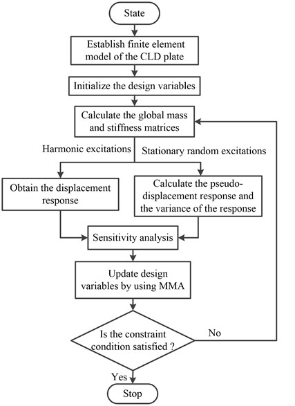
Step 1: Establish the finite element model of the plate with fully coverage of CLD treatment.
Step 2: Determine the volume fraction ratio and initialize the design variables ( 1, 2,…, ) by given uniform values.
Step 3: Calculate the global mass and stiffness matrices by the Eqs. (13)-(15).
Step 4: Obtain the displacement response through solving the state Eq. (18) if the plate/CLD system is subjected to harmonic excitations. According to PEM, calculate the pseudo-displacement response and the variance of the response if the plate/CLD system is subjected to stationary random excitations.
Step 5: The sensitivity is calculated by the AVM.
Step 6: MMA method is used to update the design variables.
Step 7: Step 3-step 6 are repeated until the constraint condition is satisfied.
6. Numerical examples
6.1. The plate/CLD system with two short edges clamped
The plate/CLD system with two short edges clamped shown in Fig. 4 is considered as a numerical example. The main physical and geometrical parameters are listed in Table 1. The loss factor of VEM layer is 0.5.
An external harmonic force is applied at the center of the plate with 10 N and . The fraction ratio of CLD is restricted to 0.5, that means 0.5 and the initial values of the design variables are set to be 0.5. Since the location of the excitation force is always the main vibration source, therefore, the optimization objective here is to minimize the displacement response amplitude at the excitation point.
Fig. 4The plate/CLD system with two short edges clamped
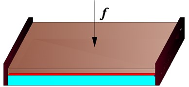
Table 1Physical and geometrical parameters of CLD plate
Length (m) | Width (m) | Thickness (mm) | Young’s modulus (MPa) | Density (kg/m3) | Poisson’s ratio | |
Base layer | 0.4 | 0.2 | 0.8 | 70 | 2800 | 0.3 |
Damping layer | 0.4 | 0.2 | 0.05 | 12(1+j) | 1200 | 0.495 |
Constrained layer | 0.4 | 0.2 | 0.13 | 70 | 2700 | 0.3 |
Table 2A comparison of the objective function between the initial and optimal design
Excitation frequency (Hz) | 10 | 100 | 150 | [10-100] | [100-200] | [200-300] |
The initial design (m) | 0.0055 | 0.0012 | 0.013 | 10.43 | 3.32 | 1.13 |
The optimal design (m) | 0.0041 | 0.00083 | 0.0027 | 7.91 | 1.91 | 0.52 |
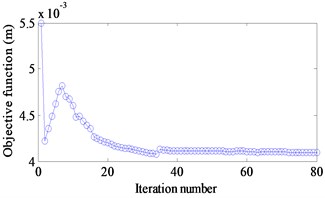
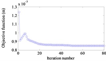
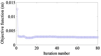
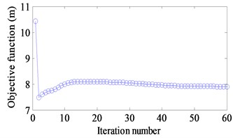
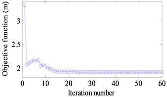
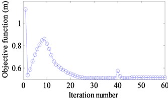
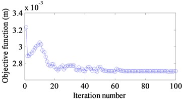
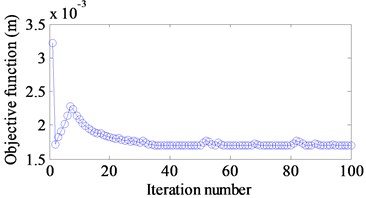
Three different excitation frequencies 10 Hz, 100 Hz and 150 Hz are addressed to obtain the optimal layout of CLD treatment. The results are demonstrated in Fig. 5(a)-(c). It is seen that the optimal layouts of the CLD treatment are different when different excitation frequencies are applied. Therefore, the dynamic design conditions such as excitation frequency should be considered in the dynamic structure design [25]. Fig. 6(a)-(c) show iteration histories of the objective function. It is noted that the objective function decreases after certain iteration number is achieved and finally convergences to a stable value. A comparison of the objective function before and after optimization is shown in Table 2. The corresponding displacement response amplitudes under different excitation frequency reduce 25 %, 31 % and 79 % respectively.
Fig. 5The optimal distributions of CLD material

a) 10 Hz

b) 100 Hz

c) 150 Hz

d) [10-100] Hz

e) [100-200] Hz

f) [200-300] Hz
Fig. 6Iteration histories of objective function value
a) 10 Hz
b) 100 Hz
c) 150 Hz
d) [10-100] Hz
e) [100-200] Hz
f) [200-300] Hz
In addition, the minimization of the displacement response amplitude over a frequency range is also selected as the objective function to verify the proposed approach. These frequency ranges are [10-100] Hz, [100-200] Hz and [200-300] Hz. The frequency interval is 0.1 Hz when the displacement response of the plate/CLD system is calculated. It can be seen that the optimal layout of CLD treatment to target a frequency or a frequency range is different obviously. However, it is clear from Table 2 that whatever frequency or frequency range, the displacement response amplitude after optimal layout is less than the original layout greatly. This verifies the influence of different layout of CLD treatment on displacement response amplitude of plate/CLD system. Fig. 6(d)-(f) show correlated iteration histories of the objective function. The same results are found. It is also noted that the displacement responses are reduced 24 %, 42 % and 54 % respectively when it is compared to the initial layout.
Fig. 7FRFs of the initial and optimal design of CLD treatment
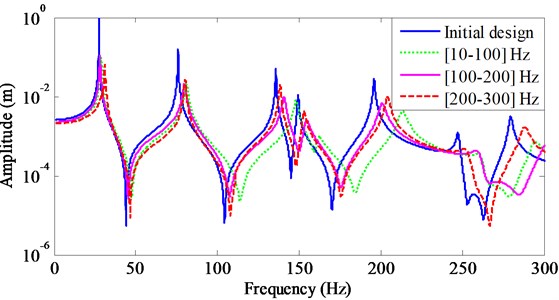
Fig. 7 shows frequency response functions (FRFs) of the initial and optimal layouts to target certain frequency range. It is noted that the peaks of frequency response at each excitation frequency range are considerably suppressed after topology optimization, which confirms that the optimal design can provide more effective vibration suppression. On the other hand, it is seen that the shift of frequency happens after topology optimization, although this shift is small. The comparisons of modal damping ratio at different frequency ranges are listed in Tables 3-5. It can be seen that all modal damping ratios increase after topology optimization although the total displacement response amplitudes over these frequency range are suppressed. It is seen that the modal damping ratios in each excitation frequency range are considerably increased after topology optimization.
Table 3A comparison of modal damping ratios over frequency range [10, 100] Hz
Modal damping ratio | First | Second |
The initial design | 0.00082 | 0.0015 |
The optimal design [10-100] Hz | 0.0094 | 0.0091 |
Table 4A comparison of modal damping ratios over frequency range [100, 200] Hz
Modal damping ratio | Third | Fourth | Fifth |
The initial design | 0.0017 | 0.0021 | 0.0016 |
The optimal design [100-200] Hz | 0.010 | 0.0086 | 0.0082 |
Table 5A comparison of modal damping ratios over frequency range [200, 300] Hz
Modal damping ratio | Sixth | Seventh |
The initial design | 0.0027 | 0.0029 |
The optimal design [200-300] Hz | 0.0101 | 0.0086 |
When the stationary stochastic excitation force with 1 N2/Hz is applied at the center of the plate, the minimization of the variance of the response at the excitation point is selected as the optimization objective. The fraction ratio of CLD is restricted to 0.5. The concerned frequency ranges are respectively [10-100] Hz and [100-200] Hz respectively. The optimal layouts of CLD treatment on the plate are shown in Fig. 8(a)-(b).
Fig. 8The optimal distributions of CLD material

a) [10-100] Hz

b) [100-200] Hz
Fig. 9Iteration histories of objective function value
a) [10-100] Hz
b) [100-200] Hz
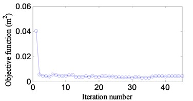
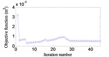
Fig. 9(a)-(b) show correlated iteration histories of the objective function. It is noted that the objective function decreases after certain iteration number is achieved and finally convergences to a stable value. A comparison of the objective function before and after optimization is shown in Table 6. The corresponding the variances of the response reduce 89 % and 90 % respectively.
Table 6A comparison of the objective function between the initial and optimal design
Frequency range (Hz) | [10-100] | [100-200] |
The initial design (m2) | 0.040 | 0.0032 |
The optimal design (m2) | 0.0045 | 0.0005 |
6.2. The cantilever plate/CLD system
Fig. 10 is a cantilever plate/CLD system with the length 0.2 m and width 0.1 m. The left short edge is clamped. Other physical and geometrical parameters are the same as the first example. The unit harmonic force is applied at the mid-point of the free edge. The goal of the design is to minimize the sum of vibration amplitudes at excitation point (B) and two end points of the free edge (A and C). In a similar way, the total displacement response amplitudes at three excitation frequencies or over three excitation frequency ranges are selected as optimized objectives. The interval of frequency range is still 0.1 Hz when the displacement response is calculated.
Fig. 10The cantilever plate/CLD system
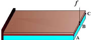
Fig. 11The optimal distributions of CLD material

a) 10 Hz

b) 50 Hz

c) 100 Hz

d) [10-50] Hz

e) [50-100] Hz

f) [100-150] Hz
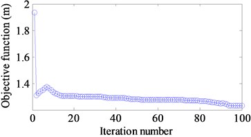
Fig. 12Iteration histories of objective function value
a) 10 Hz
b) 50 Hz
c) 100 Hz
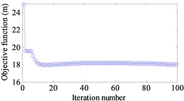
d) [10-50] Hz
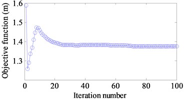
e) [50-100] Hz
f) [100-150] Hz
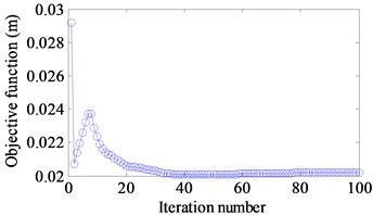
The optimal results are shown in Fig. 11(a)-(f). Fig. 12(a)-(f) demonstrate the iteration histories of the objective function when different targets are considered. The similar results are seen that the objective function reduces gradually until a stable value is achieved. A comparison of the objective function values between the initial and optimal design is illustrated in Table 7. It can be seen that the corresponding amplitudes of the displacement response at different excitation frequencies and different excitation frequency ranges have a reduction 31 %, 16 %, 47 %, 28 %, 14 % and 37 %, respectively.
Table 7A comparison of the objective function between the initial and optimal design
Excitation frequency (Hz) | 10 | 50 | 100 | [10-50] | [50-100] | [100-150] |
The initial design (m) | 0.029 | 0.0032 | 0.0032 | 24.92 | 1.59 | 1.93 |
The optimal design (m) | 0.020 | 0.0027 | 0.0017 | 18.01 | 1.37 | 1.22 |
Fig. 13FRFs of the initial and optimal designs
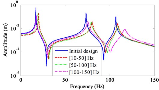
Fig. 13 illustrates FRFs of initial and optimal designs when different targets are concentrated. The same results as the first example are seen. For the excitation frequency range [10-50] Hz, the first modal damping ratio is increased from 0.00036 to 0.0082 after optimization. The second modal damping ratio is increased from 0.0022 to 0.0090 after optimization with the excitation frequency range [50-100] Hz and the third modal damping ratio is increased from 0.0016 to 0.0129 after optimization with the excitation frequency range [100-150] Hz.
When the stationary stochastic excitation force with 0.2 N2/Hz is applied at the mid-point of the free edge, the goal of the design is to minimize the sum of the variances of the response at three response points. The fraction ratio of CLD is restricted to 0.5. The concerned frequency ranges are respectively [10-100] Hz and [100-200] Hz respectively. The optimal layouts of CLD treatment on the plate are shown in Fig. 14(a)-(b).
Fig. 14The optimal distributions of CLD material

a) [10-100] Hz

b) [100-200] Hz
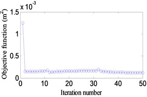
Fig. 15(a)-(b) show correlated iteration histories of the objective function. It is noted that the objective function decreases after certain iteration number is achieved and finally convergences to a stable value. A comparison of the objective function before and after optimization is shown in Table 8. The corresponding the variances of the response reduce 36 % and 91 % respectively.
Fig. 15Iteration histories of objective function value
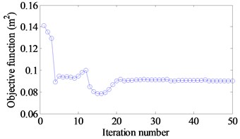
a) [10-100] Hz
b) [100-200] Hz
Table 8A comparison of the objective function between the initial and optimal design
Frequency range (Hz) | [10-100] | [100-200] |
The initial design (m2) | 0.14 | 0.0013 |
The optimal design (m2) | 0.09 | 0.00012 |
7. Conclusion
In this article, the finite element model is developed to solve dynamic optimization problem of the plate/CLD system. The complex mode superposition method is employed to calculate the steady-state response of the plate/CLD system under harmonic excitations. According to PEM, the vibration analysis of stationary stochastic excitations can be transformed to the analysis of harmonic excitations. The frequency response of plate/CLD system under harmonic excitations or stationary stochastic excitations is minimized by means of the topology optimization design of CLD treatment. The adjoint variable method is used to derive the sensitivity respect to design variable. Some important conclusions are summarized as follows:
1) The frequency response of plate/CLD system at one point or several points can be assigned as the objective function, which is possible to extend the local vibration control to the global vibration control.
2) For harmonic excitation, either external excitation frequency or frequency range may be selected as the targets in numerical examples, this provides an available method to control actual structural vibration through the optimal layout of CLD treatment on plates.
3) For stationary stochastic excitations, the concerned frequency ranges are selected as the targets in numerical examples, an available method is proposed to suppress the structural vibration through the optimal layout of CLD treatment on plates.
4) The numerical results demonstrate the effectiveness of the proposed structural dynamic topology optimization method to obtain the optimal layout of CLD treatment.
References
-
Lall A. K., Asnani N. T., Nakra B. C. Vibration and damping analysis of rectangular plate with partially covered constrained viscoelastic layer. Journal of Vibration, Acoustics, Stress, and Reliability in Design, Vol. 109, Issue 3, 1987, p. 241-247.
-
Lall A. K., Asnani N. T., Nakra B. C. Damping analysis of partially covered sandwich beams. Journal of Sound and Vibration, Vol. 123, Issue 2, 1988, p. 247-259.
-
Chen L. H., Huang S. C. Vibration attenuation of a cylindrical shell with constrained layer damping strips treatment. Computers and Structures, Vol. 79, 2001, p. 1355-1362.
-
Zheng H., Zeng H. Influence of permanent magnets on vibration characteristics of partially covered sandwich cantilever beam. Journal of Sound and Vibration, Vol. 274, 2004, p. 801-819.
-
Blais J. F., Cimmino M., Ross A., Granger D. Suppression of time abasing in the solution of the equations of motion of an impacted beam with partial constrained layer damping. Journal of Sound and Vibration, Vol. 326, 2009, p. 870-882.
-
Lumsdaine A. Topology optimization of constrained damping layer treatments. Proceedings of ASME International Mechanical Engineering Congress and Exposition, New Orleans, LA, United States, 2002.
-
Moreira R. A. S., Rodrigues J. D. Optimization of segmented constrained layer damping with mathematical programming using strain energy analysis and modal data. International Journal of Structural Stability and Dynamics, Vol. 6, 2006, p. 397-411.
-
Lepoittevin G., Kress G. Optimization of segmented constrained layer damping with mathematical programming using strain energy analysis and modal data. Materials and Design, Vol. 31, Issue 7, 2010, p. 14-24.
-
Zheng L., Xie R. L., Wang Y., Adel E. S. Topology optimization of constrained layer on plates using method of moving asymptote MMA approach. Shock and Vibration, Vol. 18, 2011, p. 221-244.
-
Ansari M., Khajepour A., Esmailzadeh E. Application of level set method to optimal vibration control of plate structures. Journal of Sound and Vibration, Vol. 322, Issue 4, 2013, p. 687-700.
-
Kim S. Y., Mechefske C. K., Kim Y. Optimal damping layout in a shell structure using topology optimization. Journal of Sound and Vibration, Vol. 322, 2013, p. 2873-2883.
-
Chen W., Liu S. Topology optimization of microstructures of viscoelastic damping materials for a prescribed shear modulus. Structural and Multidisciplinary Optimization, Vol. 50, 2014, p. 287-296.
-
Jog C. S. Topology design of structures subjected to periodic loading. Journal of Sound and Vibration, Vol. 253, 2002, p. 687-709.
-
Jog C. S. Reducing radiated sound power by minimizing the dynamic compliance. Proceedings of the IUT.AM Symposium on Designing for Quietness, Bangalore, India, HIuwer, Dordrecht, 2002.
-
Du J., Olhoff N. Minimization of sound radiation from vibrating bi-material structures using topology optimization. Structural and Multidisciplinary Optimization, Vol. 33, 2007, p. 305-321.
-
Nandy A. K., Jog C. S. Optimization of vibrating structures to reduce radiated noise. Structural and Multidisciplinary Optimization, Vol. 45, 2012, p. 717-728.
-
Rong J. H., Xie Y. M., Yang X. Y., Liang Q. Q. Topology optimization of structures under dynamic response constraints. Journal of Sound and Vibration, Vol. 234, Issue 2, 2000, p. 177-189.
-
Moshrefi-Torbati M., Keane A. J., Elliot S. J., et al. Passive vibration control of a satellite boom structure by geometric optimization using genetic algorithm. Structural and Multidisciplinary Optimization, Vol. 267, 2003, p. 879-892.
-
Zheng H., Cai C., Pau G. S. H., Liu G. R. Minimizing vibration response of cylindrical shells through layout optimization of passive constrained layer damping treatments. Journal of Sound and Vibration, Vol. 279, Issue 3-5, 2005, p. 739-756.
-
Zheng H., Pau G. S. H., Wang Y. Y. A comparative study on optimization treatment for structural of constrained layer damping vibration control. Thin-Walled Structures, Vol. 44, 2006, p. 886-896.
-
Hussein M. I., Hamza K., Hulbert G. M., et al. Multiobjective evolutionary optimization of periodic layered materials for desired wave dispersion characteristics. Structural and Multidisciplinary Optimization, Vol. 31, 2006, p. 60-75.
-
Alvelid M. Optimal position and shape of applied damping material. Journal of Sound and Vibration, Vol. 310, Issue 4, 2008, p. 947-965.
-
Dede E. M., Hulbert G. M. Topology optimization of structures with integral compliant mechanisms for mid-frequency response. Structural and Multidisciplinary Optimization, Vol. 39, 2009, p. 29-45.
-
Yoon G. H. Structural topology optimization for frequency response problem using model reduction schemes. Computer Methods in Applied Mechanics and Engineering, Vol. 199, 2010, p. 1744-1763.
-
Shu L., Wang M. Y., Fang Z., et al. Level set based structural topology optimization for minimizing frequency response. Journal of Sound and Vibration, Vol. 310, Issue 4, 2008, p. 947-965.
-
Lin J. H., Zhao Y., Zhang Y. H. Accurate and highly efficient algorithms for structural stationary/non-stationary random responses. Computer Methods in Applied Mechanics and Engineering, Vol. 191, Issue 1, 2001, p. 103-111.
-
Kang Z., Zhang X.,·Jiang·S., et al. On topology optimization of damping layer in shell structures under harmonic excitations. Structural and Multidisciplinary Optimization, Vol. 46, Issue 1, 2012, p. 51-67.
-
Bendsoe M. P. Optimal shape design as a material distribution problem. Structural Optimization, Vol. 1, 1989, p. 193-202.
-
Svanberg K. The method of moving asymptotes: a new method for structural optimization. International Journal for Numerical Method in Engineering, Vol. 24, 1987, p. 359-373.
About this article

The support from the Natural Science Foundation of China (Grant No. 50775225) and the Research Foundation of State Key Laboratory of Mechanical Transmission (Grant No. 0301002109165) is gratefully acknowledged.
