Abstract
Featured by advantages of low speed, large torque, fast response and being free from external magnetic field interference, the linear ultrasonic motor enjoys fast development in recent years. The single layer U-shaped motor has a flat structure as it makes use of d31 effect of piezoelectric ceramics and adopts integrated vibrators, but its output force is unsatisfactory. In this paper, the structure of the linear ultrasonic motor with a laminated stator was proposed, which was made of two identically single U-shaped stators. The finite element model for stators of ultrasonic motor was built by ANSYS to carry out modal analysis and structure optimization. The workbench of the motor was designed by PROE, and then, the designed stators and workbench were processed and assembled into a motor. The swept-sine modal test was carried out to verify the feasible of the simulation. Finally, the mechanical performance of the laminated ultrasonic motor was tested, and comparison was also carried out with single layer U-shaped ultrasonic motor. The results showed that the maximum output force of the laminated motors increases by 40 % than that of single layer U-shaped motor, while the maximum velocity increased by 38 %, which showed that the mentioned design of the laminated ultrasonic motor was feasible. Finally, in order to further expand application of the linear ultrasonic motor designed in this paper, it was compared with the existing linear ultrasonic motors in terms of assembly and mechanical performances in this paper. It is shown that the linear ultrasonic motor designed has more prominent performances in these aspects.
1. Introduction
The traditional electromagnetic motors have become very mature in theories, structural design, production, manufacture and applications through nearly 100 years. With development of science and technologies, current fields such as aerospace, precise instruments and medical instrumentations have put forward more new requirements for motors, such as small length, low noise, light weight, and freedom from electromagnetic interference. As a result, the traditional electromagnetic motors can no longer satisfy these requirements, because they were limited by operation principles, structural forms and so forth [1-3]. Therefore, it was necessary to research and produce new type of motors to take place of electromagnetic motors in some fields. The ultrasonic motor was one of the advanced micro motors. Its appearance made up deficiencies of the traditional electromagnetic motors.
As a type of ultrasonic motors, the linear ultrasonic motor can realize highly precise location and velocity control except for advantages owned by the common ultrasonic motors. It had also a simple structure and low cost for production and maintenance [4, 5]. It can also adopt multiple shapes. Therefore, it was widely used.
At present, the linear ultrasonic motor has been researched by a lot of scholars [6]. Fornandez conducted the detailed analysis of the linear ultrasonic motor and pointed out its advantages from theories [7]. Frangi carried out simulation of mechanical performances for the linear ultrasonic motor based on the finite element method and obtained a new type of motor with more prominent mechanical performances [8]. Lu designed a new type of linear ultrasonic motor with double drive feet, and its mechanical performances were researched by combining experiments with simulation [9]. In addition, Smithmaitrie observed change trends of mechanical performances for the linear ultrasonic motor by changing parameters of piezoelectric ceramic pieces [10].
However, the linear ultrasonic motors with laminated type and plate attached type stators [11] were mainly adopted in the mentioned researches. The linear ultrasonic motor with laminated type stator which made use of d33 effect of piezoelectric ceramics had large output force and high energy conversion rate, but it had a complicated structure and it’s also difficult to be assembled. The linear ultrasonic motor with plate attached type stator had flat structure, and it made use of d31 effect of piezoelectric ceramics and adopted integrated vibrators. However, its output force was unsatisfactory. Based on the advantages of the two types of motors, the linear ultrasonic motor with a laminated U-shaped stator was proposed in this paper, which stator was consists of two identical U-shaped stators. This type motor can simplify the structure to meet the requirement of dimensions and can also solve the problem of low operation efficiency and small output. There has been no research on this type of ultrasonic motor so far. Therefore, the structural design of this kind of motor was very meaningful.
2. Basic theory
2.1. Theory of the motor
The uniform rectangular thin sheet has mainly three basic vibration modes. The first is retractable mode in-plane, the second is bending mode in-plane and out-of-plane, and the third is torsional mode in-plane. The other modes are made of the mentioned three basic modes. With mode in-plane as the operation mode of linear ultrasonic motor, the structure can be simple [12].
The ultrasonic motor can operate normally when the resultant movement of the particles on the surface of stator or rotor is elliptical motion. The quality of the elliptical orbit will directly affect the output performance of the linear ultrasonic motor [13]. Generally, lower order of vibration mode should be selected to acquire larger mechanical output force. The operation mode of the ultrasonic motor designed in this paper is retractable mode and bending mode in plane of stators.
Piezoelectric ceramic pieces will excite the stators to enable them to achieve the work condition of the first-order longitudinal vibration and the second-order bending vibration. Longitudinal vibration mainly causes the horizontal displacement to drive the movement of the guide rail, while bending vibration mainly causes vertical displacement to appear intermittent contact and separation between the stators and the guide rail. Under the function of pre-compression, the superposition of the two modes enables the stators to rub with the guide rail intermittently, and then the guide rail is driven by the friction to form rectilinear motion. When the phase difference between the two modes is 90°, an elliptical motion orbit will be formed at the contact points.
2.2. Modal analysis on the motor
To learn the basic vibration characteristics of the stator structure, modal analysis was carried out on the stator structure by using its resonance feature.
Under the condition of linear time invariant, the vibration equation of a continuous structure system is:
where is the mass matrix of the system. is the damping matrix of the system. is the stiffness matrix of the system. is the displacement response vector of the system. is the excitation force vector of the system.
The finite element vibration equation of the system without considering damping is:
Its solution can be assumed as the following form:
where is the th order vector. is the vibration frequency of vector . is initial phase angle, which can be determined according to the initial conditions. Substitute Eq. (3) into Eq. (2) to obtain the follows:
characteristic solutions ,,…, can be acquired by solving the mentioned equation, where characteristic values , ,…, represent inherent frequencies of the system, characteristic vectors , ,…, , represent inherent vibration modes of the system.
The following orthogonal characteristic exists between the inherent vibration modes of the structure and the mass matrix as well as the stiffness matrix :
where and are referred to the matrix of inherent frequencies and the matrix of inherent vibration modes, respectively.
3. Structure design of the laminated U-shaped stator
3.1. Laminated U-shaped stator
The stator structure was designed to the following type which was made of two parts of metal elastomer and piezoelectric ceramic pieces, where the metal elastomer was U-shaped structure [14] which was made of beryllium copper through wire cutting. Meanwhile, flexible clamps with bolt holes were cut on both sides of the U-shaped elastomer [15]. The stators were fixed on the base by bolts. The rotors were driven to move by the drive foot which was the top point of the U-shaped stator [16]. Piezoelectric ceramic pieces were pasted on the vibration rods which was two feet of the U-shaped stator, and the piezoelectric material was PZT8.
The selected operation mode is the first-order longitudinal mode and the second-order bending mode. Firstly, the finite element model of the laminated U-shaped stator was built by ANSYS software, then modal analysis was carried out and parameters of the single stator were optimized by means of parameter optimization function as the following. The height of the drive foot was the variable parameter, while other structure parameters were unchanged. The structure would have an optimal parameters when the work frequencies of the first-order longitudinal vibration modal and the second-order bending vibration modal were very close, and there was no other modal interference near this frequency. The optimal parameters were shown in Fig. 1, and the geometry model of the laminated U-shaped stator was shown in Fig. 2.
The first-order longitudinal mode and the second-order bending mode of the laminated U-shaped stator were obtained by the finite element model as shown in Fig. 3 and Fig. 4.
The frequency of the first-order longitudinal vibration and the second-order bending vibration was obtained as shown Table 1. The difference value between the two operation frequency was 192 Hz, which could meet the requirement of frequency consistency.
Fig. 1Parameters of the laminated U-shaped stator after optimization
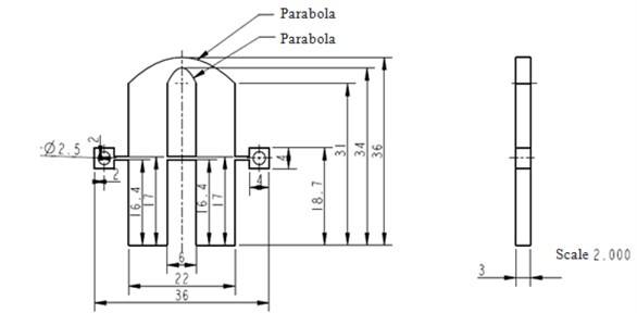
Fig. 2Diagram of the geometry model for the laminated stator
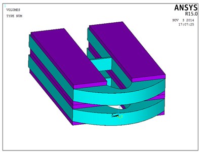
Fig. 3Diagram of the first-order longitudinal mode
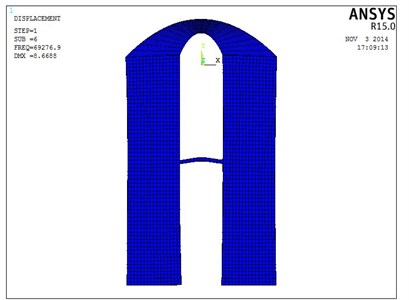
Fig. 4Diagram of the second-order bending mode
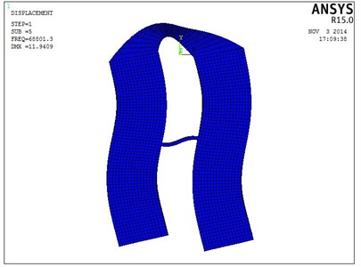
Table 1Operation frequency of the motor
Operation mode | Frequency / Hz | Difference value / Hz |
First-order longitudinal mode | 58257 | 192 |
Second-order bending mode | 58449 |
3.2. Integrated design of the motor structure
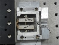
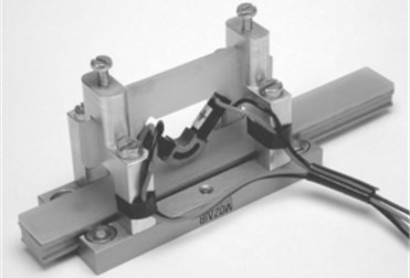
The workbench of common ultrasonic motor can be purchased directly. However, the structure of the laminated motor was special. In this paper, a precise workbench was designed based on the advantages of linear ultrasonic motor as shown in Fig. 5. It had the following characteristics. Firstly, there was no mechanical friction between the workbench and the guide rail as well as the drive foot. Secondly, the inherent frequency of the workbench was far from the operation frequency of the motor to avoid resonance. The detailed structure parameters of the workbench was shown in Fig. 6, and the final real ultrasonic motor was obtained through processing and assembling as shown in Fig. 7.
Fig. 5The workbench of the laminated motor
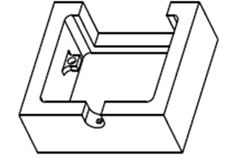
Fig. 6Structural parameters of the workbench
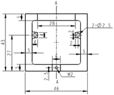
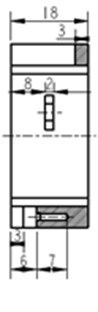
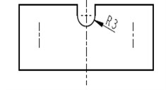
Fig. 7Diagram of the real ultrasonic motor
3.3. Experimental verification of the simulation analysis
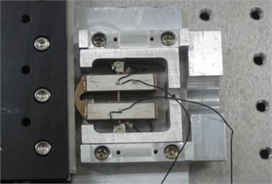
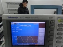
In order to verify the feasible of the simulation analysis, the swept-sine modal test by means of HP35670A which was a dynamic signal analyzer was carried out on the real laminated ultrasonic motor. The experiment results were shown in Fig. 8, it could be seen from the figure that the frequency of the first-order longitudinal vibration and the second-order bending vibration were 58.33 kHz and 58.49 kHz, respectively. They were consistent with the simulation results, which showed that the simulation analysis was feasible.
Fig. 8Experimental results of the swept-sine modal test
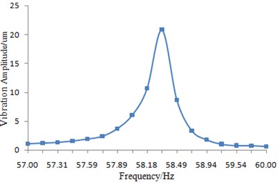
a) The frequency of the first-order longitudinal vibration
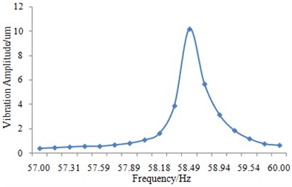
b) The frequency of the second-order bending vibration
4. Experiment and analysis on the mechanical performance
4.1. Experiment design
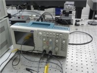
The mechanical performance test of the laminated motor and single U-shaped motor was completed by the experimental facility as shown in Fig. 9. The driving platform of the motor is composed of signal generator and power amplifier, and the motor performance test system is composed of motor, force sensor and oscilloscope. The driving platform of the motor controls the output mechanical performance of the motor by adjusting the amplitude, phase and frequency of the input signals in certain range. The output performances such as the no-load velocity, acceleration and output force of the motor can be measured by the test system. Meanwhile, the influence of the pre-compression force on the mechanical performance of the motor can be researched by the force sensor.
The operation frequency had been obtained by simulation and experiment, so the test frequency of the motor was controlled in the range of 57.5 kHz-59.5 kHz, hence, the motor performance could be ensured to be in a good operation status.
Fig. 9Experimental facility of the mechanical performance test
a) Ultrasonic motor
b) Signal generator
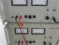
c) Power amplifier
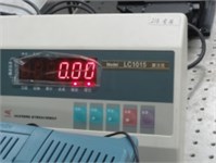
d) Dynamometer
e) Oscilloscope
f) Winanal software
4.2. Experimental results and analysis
In order to decide the most appropriate operation frequency of the laminated ultrasonic motor, we tested the mechanical performance of the laminated ultrasonic motor under different operation frequency as shown in Fig. 10.
Fig. 10The mechanical performance of the laminated ultrasonic motor
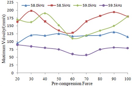
a) The maximum velocity with the change of pre-compression force
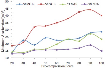
b) The maximum acceleration with the change of pre-compression force
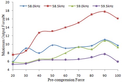
c) The maximum output force with the change of pre-compression force
It could be seen from Fig. 10 that the mechanical performance such as velocity, acceleration and output force had an obvious change with the operation frequency. In addition, the laminated ultrasonic motor would achieved a better performance in 58.5 kHz, because this frequency was more close to the frequency of the first-order longitudinal vibration and the second-order bending vibration, which were the main operation modal. Moreover, the mechanical performance of the laminated ultrasonic motor had a larger change with the increase of the pre-compression force. There should be an optimum numerical of pre-compression force, and its value should be determined by different application condition. In order to verify the advantages of the laminated ultrasonic motor, the optimal mechanical performance was compared with that of the single U-shaped motor as shown in Fig. 11 and Fig. 12.
Fig. 11Comparison of the maximum velocities between two types of ultrasonic motor
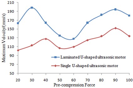
Fig. 12Comparison of the maximum output force between two types of ultrasonic motor
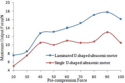
It could be seen from Fig. 11 and Fig. 12 that the mechanical performance of the laminated was better than that of the single U-shaped motor, and the detailed description was shown in the following. Under the operation frequency of 58.5 kHz, the maximum output force of the single U-shaped motor was approximate 13 N, and its maximum velocity was 145 mm/s. However, under the same operation frequency, the maximum output force of the laminated motor was approximate 18 N, and its maximum velocity was 200 mm/s. The maximum output force of the laminated motor increased by approximate 40 % than that of the single U-shaped motor, while the maximum velocity increased by 38 %. This result was satisfactory, which showed that the mentioned design of the laminated ultrasonic motor was feasible.
5. Advantages of linear ultrasonic motor with a laminated U-shaped stator
The ultrasonic motor designed had prominent mechanical performances when it was compared with the single U-shaped ultrasonic motor. However, it was still necessary to research whether its performances were better than those of other existing linear ultrasonic motors in order to expand application. It was pointed out in introduction that the linear ultrasonic motors which were widely used at present were mainly divided into two types, and they were laminated type and plate attached type, respectively. As a result, the traditionally laminated linear ultrasonic motor and plate attached linear ultrasonic motor were selected to test their mechanical performances. Three types of motors had similar operation modals in order to make that the subsequent comparison was rigorous. And then, maximum velocities and output forces of two types of traditionally linear ultrasonic motors were tested, respectively. These parameters can be used to show mechanical performances of the linear ultrasonic motors. The experimental diagram was shown in Fig. 13. Results of this experiment were compared with the laminated U-shaped linear ultrasonic motor, as shown in Fig. 14 and Fig. 15.
Fig. 13Experimental diagram of the traditionally linear ultrasonic motors
a) Traditional laminated linear ultrasonic motor
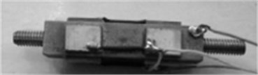
b) Traditional plate attached linear ultrasonic motor
It was shown in comparison between Fig. 7 and Fig. 13 that the traditionally laminated linear ultrasonic motor had a complicated structure and was relatively difficult in assembly. The traditionally plate attached linear ultrasonic motor and the motor designed in this paper had a relatively simple structure and occupied much smaller volumes. Therefore, the linear ultrasonic motor designed in this paper had certain superiorities.
Fig. 14Comparison of maximum velocities between three types of linear ultrasonic motors
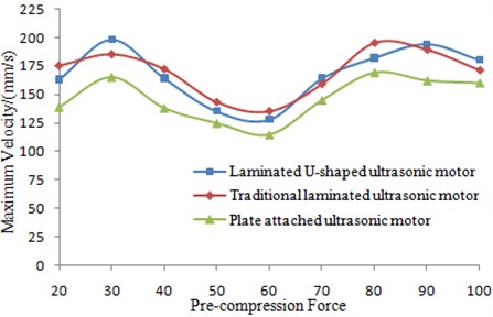
Fig. 15Comparison of maximum output forces between three types of linear ultrasonic motors
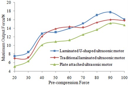
It was shown in Fig. 14 that maximum velocities of two types of laminated linear ultrasonic motors were much larger than that of the plate attached type. This result was consistent with the existing researches. In addition, maximum velocities of two types of laminated linear ultrasonic motors had very small differences. It was shown in Fig. 15 that maximum output force of the laminated U-shaped linear ultrasonic motor was obviously larger than those of other two types of ultrasonic motors. Therefore, the laminated U-shaped linear ultrasonic motor also had relatively prominent mechanical performances.
Advantages of two types of traditionally ultrasonic motors were integrated into the laminated U-shaped linear ultrasonic motor. As a result, the U-shaped linear ultrasonic motor had obvious superiorities in assembly and mechanical performances. It had been also put into production and application at present.
6. Conclusions
In this paper, structure design of the laminated ultrasonic motor is proposed innovatively. The motor structure is designed and optimized by PROE and ANSYS software. Output performance experiment and modal experiment are carried out after assembly. The following conclusions can be obtained.
1) The optimum operation frequency of the single U-shaped motor and the laminated motor are both approximate 58.5 kHz, and the laminated-shape in height basically has no influence on the operation efficiency.
2) Under the operation frequency of 58.5 kHz, the maximum output force of the single U-shaped motor was approximate 13 N, and its maximum velocity was 145 mm/s. However, under the same operation frequency, the maximum output force of the laminated motor was approximate 18 N, and its maximum velocity was 200 mm/s. The maximum output force of the laminated motor increased by approximate 40 % than that of the single U-shaped motor, while the maximum velocity increased by 38 %. This result was satisfactory, which showed that the mentioned design of the laminated ultrasonic motor was feasible.
3) Pre-compression force has a huge influence on the mechanical characteristics of the ultrasonic motor. When the input voltage and excitation frequency are constant, the maximum velocity and output force are different under different pre-compression force. There should be an optimum numerical of pre-compression force, and its value should be determined by different application condition.
4) The mechanical performance of the laminated ultrasonic motor is improved significantly when it is compared with that of the single U-shaped motor. Moreover, its motor structure is simple.
5) It is compared with the existing linear ultrasonic motors in terms of assembly and mechanical performances in this paper. It is shown that the linear ultrasonic motor designed has more prominent performances in these aspects.
References
-
Zhao C. S. Technology and Application of Ultrasonic Motor. Science Press, Beijing, 2007, p. 1-20.
-
Zhao C. S. Recent progress in ultrasonic motor techniques. Journal of Vibration, Measurement and Diagnosis, Vol. 24, Issue 1, 2004, p. 1-5.
-
Wallaschek J. Contact mechanics of piezoelectric ultrasonic motors. Smart Materials and Structures, Vol. 12, Issue 7, 1998, p. 369-381.
-
Sashida T. Motor Device Utilizing Ultrasonic Oscillation. U.S. Patent 4,562,374, 1985.
-
Hagedorn P., Wallaschek J. Traveling wave ultrasonic motors. Part 1: working principle and mathematical modeling of the stator. Journal of Sound and Vibration, Vol. 155, Issue 1, 1992, p. 31-46.
-
Deng X. S., Wu G. X. Research statement and issues of linear ultrasonic motor. Micro-Motors Servo Technique, Vol. 38, Issue 5, 2005, p. 78-81.
-
Fernandez J. M., Perriard Y. Comparative analysis and modeling of both standing and travelling wave ultrasonic linear motor. IEEE Symposium on Ultrasonics, Vol. 2, 2003, p. 1770-1773.
-
Frangi A., Corigliano A., Binci M., et al. Finite element modeling of a rotating piezoelectric ultrasonic motor. Ultrasonics, Vol. 43, Issue 9, 2005, p. 747-755.
-
Lu C., Xie T., Zhou T., et al. Study of a new type linear ultrasonic motor with double-driving feet. Ultrasonic, Vol. 44, 2006, p. 585-589.
-
Smithmaitrie P., Suybangdum P., Laoratanakul P., et al. Design and performance testing of an ultrasonic linear motor with dual piezoelectric actuators. IEEE Transactions on Ultrasonic, Ferroelectrics and Frequency Control, Vol. 59, Issue 5, 2012, p. 1033-1042.
-
Jin J. M., Shi Y. L., Li Y. B. Research on novel inertial linear ultrasonic piezoelectric motor. Optics and Precision Engineering, Vol. 16, Issue 12, 2008, p. 2372-2377.
-
Hu B. Z., Li Y. G. Design and analysis of a new ultrasonic motor vibrator with longitudinal and bending modes. Piezoelectrics and Acoustooptics, Vol. 36, Issue 3, 2014, p. 353-356.
-
Wan Z. J., Hu H. The mathematical model and experimental study on linear ultrasonic motor using longitudinal and bending mode. Piezoelectrics and Acoustooptics, Vol. 35, Issue 2, 2013, p. 229-233.
-
Su S. F., Yao Z. Y., Geng R. R. Structure design of a linear ultrasonic motor with an U-shaped vibrator. Journal of Harbin Engineering University, Vol. 33, Issue 6, 2012, p. 760-762.
-
Tokiya W., Minuro K. K., Toshiro H. Transducer for all ultrasonic linear motor with flexible driving part. IEEE Ultrasonic Symposium, Miyagi, Japan, 1998, p. 683-685.
-
Lee Y., Kim W. A high power and precision ultrasonic linear motor with lateral flexible. Towards Synthesis of Micro Nano Systems, Vol. 2, Issue 4, 2007, p. 101-106.
About this article

