Abstract
T-tail has a more prominent problem of structural vibration, meanwhile, the problems of static strength and stability of its structure can not be ignored. Since T-tail structure is complex, it has multi-variables to optimize and the constraint functions of static strength, stability and vibration are quite different. Therefore it is difficult to get the optimal results through once optimization. This paper firstly set up a wind tunnel experiment of T-tail to test its aerodynamic characteristics. Then, the experimental results were compared with that of the simulation to verify the reliability of the simulation model. Based on the verified model, the influence factors on T-tail vibration characteristic were analyzed which can be set as the constraint of the subsequent optimization problem. At last, this paper considered the multi-disciplinary optimization problems of T-tail based on static strength, stability and vibration, used the idea of multi-level optimization, and designed a rational optimization scheme. And then the structure optimization of T-tail was carried out by the proposed scheme. Finally, the mass of T-tail is greatly reduced, and it also meets the design requirements of static strength, stability and vibration. The comprehensive performance is superior, which can also provide some reference to the multi-disciplinary optimization design of other similar structure.
1. Introduction
T-tail was a special aerodynamic structure. When incidence angle was small, this layout form can make the horizontal tail avoid the influence of wing flow, and the control efficiency of the horizontal tail was higher [1]. Moreover, this layout was convenient for the open body at latter airframe, and it was also conductive to transport the goods. So the design of many large aircraft has adopted T-tail.
Research about vibration characteristics of T-tail was relatively early. References [2-4] analyzed the influence of dihedral angle on a horizontal tail and steady lift on T-tail vibration characteristics. References [5-6] also carried out the relevant experiment research for T-tail. Lv [7] combined the subsonic double-lattice method with strip theory and researched the calculation methods for T-tail unsteady aerodynamics. Qiu [8] explained that support stiffness had a larger influence on T-tail vibration.
About the structural optimization of T-tail, Lv [9] carried out the structural vibration optimization of T-tail by using genetic-sensitivity algorithm and dynamic simplified model, and the calculation efficiency was higher. However, the dynamic simplified model can not consider the constraints of static strength, stability. Cai [10, 11] carried out the structural optimization for composite T-tail based on static strength, stiffness and stability by using Nastran software, and explored the effect of the composite ply orientation on the final optimization results. And so far, there was little published paper to conduct comprehensive consideration on T-tail static strength, stability and vibration. Due to that T-tail structure was very complex, and more optimization variables, larger differences of constraints functions, we can not get the ideal optimization results once. This paper released the constraint requirements of stiffness based on full knowledge of T-tail vibration characteristics, and then we used multi-level optimization method to carry out multidisciplinary optimization for T-tail structure based on static strength, stability and vibration. Finally, the optimization effect was significant, and it had higher engineering value and significance.
2. The vibration calculation method of T-tail
For T-tail vibration, because of the particularity of structure and appearance, its vibration characteristics are different from the conventional wing. The vibration of T-tail is bending-torsional coupled vibration of the vertical tail, meanwhile, the horizontal tail also has a great influence on the T-tail vibration. Firstly, from the structure aspect, the rotational inertia of the vertical tail was increased, which made the vertical tail bending-torsional frequencies close and reduced the vibration speed of the vertical tail bending-torsional coupling form. Secondly, in terms of aerodynamic, the horizontal and lateral aerodynamic coupling of the tail is severe, which can lead to the decrease of T-tail vibration speed.
For the calculation of T-tail vibration, we can solve the natural vibration equation in Eq. (1) by the finite element software:
In the formula, and is respectively the inertial force and the elastic force of the structure. For solving this equation, when it was expressed by the modal coordinates. Then the Eq. (1) is left multiplied by and the decoupling equation can be obtained as Eq. (2):
where, is the generalized mass diagonal matrix, is the generalized stiffness diagonal matrix, is the generalized coordinates array. Typically, if the modal matrix is a mass normalized matrix, then:
Add the aerodynamic items to the right of Eq. (2), we can obtain the general motion equation of aeroelastic [12], as follows:
where, is the generalized unsteady aerodynamic matrix, in a typical vibration problem, it is generally calculated by double-lattice method.
For the influence of the horizontal tail aerodynamic on the bending-torsional coupling vibration of the vertical tail, the double-lattice method can fully consider the aerodynamic interference between the horizontal tail and the vertical tail. However, it can’t account for the unsteady effect of the horizontal tail’s steady lift, so the vibration speed calculated by the double-lattice method will be high, and can't guarantee the structure security. We can refer to the strip method of the reference [7], divide the horizontal tail into a series of strips along span. And we can ignore any element’s tangential deformation, and see it as a rigid body. Calculating the changes of the steady lift caused by the movement of the strips, and considering the impact of the dihedral angle, finally, we can establish the followed aerodynamic equation:
where, is the aerodynamic influence coefficient matrix, is the freedom of movement.
Furtherly, convert the unsteady aerodynamic obtained by Eq. (5) to the modal coordinates, the corresponding modal matrix can be constructed by interpolating, as follows:
Thus, the unsteady effect of the horizontal tail steady lift can be expressed as:
Therefore, the total unsteady aerodynamics of T-tail can be divided into two items, which are the conventional unsteady aerodynamic item and unsteady effect of the horizontal tail’s steady lift item. For conventional unsteady aerodynamic item, it still can be analyzed using the subsonic double-lattice method, while the unsteady effect of horizontal tail lift item can be calculated by the Eq. (5)-(7). Eventually, they will be superimposed on the modal coordinates, we can get the total generalized unsteady aerodynamic of T-tail as follows:
where is the conventional unsteady aerodynamic item. is the unsteady effect of horizontal tail’s steady lift item.
In the detailed implementation, we can carry out vibration calculations through the conventional software such as Nastran. Then, the conventional unsteady aerodynamic matrix for each equivalent frequency is obtained. Meanwhile, calculate the unsteady effect of the horizontal tail unsteady lift matrix , and carry out their superposition. The final unsteady aerodynamic matrix for each equivalent frequency is obtained. Then, submit these matrices to the vibration computing software for the final vibration calculation, we can get the V-g figure and the V- figure and also can get the final speed and frequency of vibration.
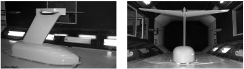
Fig. 1Wind tunnel experiment diagram of T-tail
3. The wind tunnel experiment and simulation model verification of T-tail
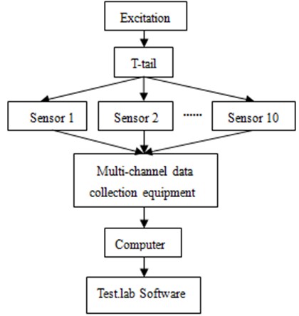
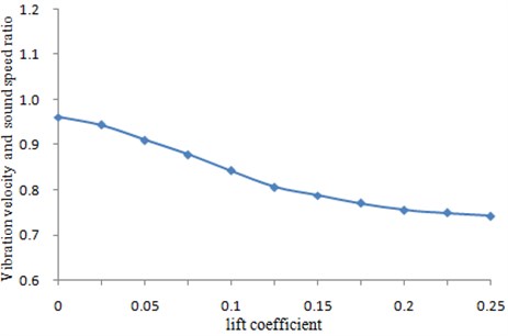
During the experiment, it was very difficult to fix a single T-tail in the wind tunnel. Therefore, the fixture was mounted under T-tail, as shown in Fig. 1. The lower surface of the fixture was tightly bonded with the wind tunnel floor to ensure that T-tail was stable in the experiment process and the experimental result will not be effect. Ten sensors were arranged on T-tail to test its vibration velocity when the stable wind speed was formed. The back-sweep angle of T-tail was 31°, and incidence angle was 0°. During the experiment, the lift coefficient was changed to observe the vibration velocity of T-tail. The experimental process diagram was shown in Fig. 2. The signal received in the sensor was transferred to the multi-channel data collection equipment, and then the Test.lab software was adopted for processing data, whose results were shown in Fig. 3. With the changes of lift coefficient, the vibration velocity of T-tail was constantly changing.
Fig. 2Wind tunnel experiment process of T-tail
The costs will be increased and efficiency will be reduced undoubtedly if we studied T-tail by wind tunnel experiment only. Therefore, the simulation method was selected subsequently to research T-tail. According to structure of T-tail in the experiment, its aerodynamic mesh model was established, as shown in Fig. 4, which had 31644 elements and 26713 nodes in total.
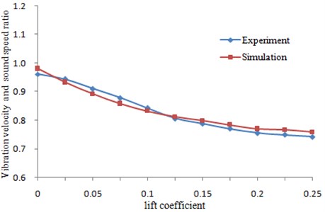
The boundary conditions which were same as that of the experiment were added in the mesh model of Fig. 4 to simulate the experimental process. The calculation results were compared with the experimental values as shown in Fig. 5. As can be seen from Fig. 5, both the value and change trend were very close between experiment and simulation, which indicated that the simulation model was reliable and could be used to accurately predict T-tail characteristics.
Fig. 3Change of vibration velocity for T-tail
4. Analysis of influence factors on T-tail vibration
Based on the verified model, the influence factors on T-tail vibration were analyzed by changing parameters on the horizontal tail structure such as dihedral angle, incidence angle and back-sweep angle. This research can provide a certain basis for the subsequent optimization of vibrations. Designers can make the influence factors set as the constraints of subsequent optimization to obtain a better structure.
Fig. 4Aerodynamic mesh model of T-tail
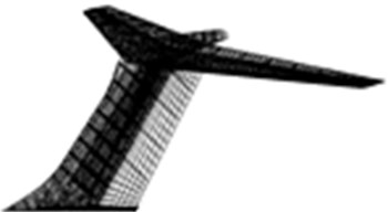
Fig. 5Comparison of vibration velocity between experiment and simulation for T-tail
4.1. Influences of dihedral angle and incidence angle on the vibration velocity
The vibration velocity was calculated by changing dihedral angle of the horizontal tail and incidence angles, and results were shown in Fig. 6. Changes in the horizontal tail incidence angle aimed at changing lift coefficient of the horizontal tail. It was shown in Fig. 6 that the vibration velocity obviously increased with decrease in dihedral angle. The vibration velocity obviously decreased with increase in incidence angle.
Fig. 6Changing curve of the vibration velocity with dihedral angle and incidence angle
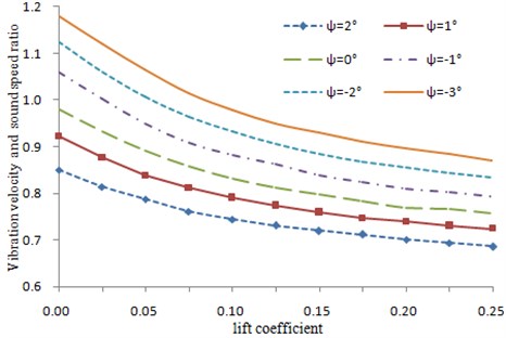
A bigger incidence angle caused bigger static lift force. As a result, lateral force generated from rolling will increase. Then, the total unsteady aerodynamic force of tail will further increase, under the structure mass and rigidity was changeless, the vibration velocity decreased. Obviously, a negative dihedral angle shall be used in the horizontal tail during T-tail design in order to ensure enough vibration velocity of T-tail.
4.2. Influences of back-sweep angle on the vibration velocity
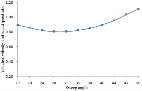
Under other parameters were changeless, the vibration velocity was obtained by changing the back-sweep angle of the horizontal tail, as shown in Fig. 7. It was shown in the figure that when the back-sweep angle of horizontal tail was changed, the vibration velocity decreased slowly at first and then increased. The vibration velocity did not vary much within the angle between 20°-38°. However, it increased relatively quickly when the angle exceeded 40°. Increasing in the back-sweep angle would reduce the control efficiency of the horizontal tail, and had an effect on the structural model at the same time. Therefore, during design of a T-tail structure, the back-sweep angle shall be comprehensively decided by multiple factors.
According to the mentioned analysis, we can make the influence factors set as the constraints of the subsequent optimization to obtain a structure which met the requirements of the design.
Fig. 7Changing curve of vibration speed with back-sweep angle
5. The design of optimization
5.1. Optimization analysis of static strength and stability
Static strength optimization was a common problem, and its single-step calculation time was short. Through the rational use of SQP, we can get the ideal optimization results. The optimization module of software Nastran provided a solution to this problem, and it still had high calculation efficiency in the case of more optimization variables.
For stability optimization, its single-step calculation time was relatively long, and its constraint functions were more complex. It not only had low optimization efficiency but also poor robustness through the direct use of mathematical method. The optimal results had a great relationship with the initial selection of the variables. In addition, iteration requires re-modeling, and also made the optimization difficult. Later, the reversed design based on the stability design criteria can greatly improve the optimization efficiency as follows:
Among them, the Eq. (9) is an expression in simply supported case, the Eq. (10) is an expression in clamped case. In the formula, is the bending stiffness, is the maximum compressive strain. is obtained after the calculation of the each plane. The area and thickness have a proper ratio, and can be obtained by experience.
So, if known the plies and the corresponding maximum compressive strain, we can get the required number and size of the structure by the reversed design method. For the comprehensive optimization problem of static strength and stability, we can carry out static strength optimization; obtain the thickness and maximum compressive strain. Then, the number and thickness of the structure can be reversely solved, and then we can re-model, re-do static optimization.
5.2. Optimization analysis after adding vibration
For vibration optimization problem, if we simultaneously optimized the vibration, the static strength and the stability in a wide range, it will result in the change of the number of the structure in each step for the optimization process, so we have to re-model, which greatly increased the optimization workload and even led to optimization failure. Therefore, we must consider the characteristics of T-tail vibration, select appropriate optimization variables and algorithm to optimize it.
5.3. Final optimization scheme
For the T-tail comprehensive optimization, we can start the preliminary optimization of the structure base on static strength and stability, so that the horizontal tail and vertical tail structure can reach the goal of minimum weight. The skin, the beam and other main load-bearing components of the vertical tail were set as the optimization variables, and then the static strength, stability were optimized. Finally, the influence factors such as dihedral angle, incidence angle and back-sweep angle on T-tail vibration were set as the constraints of the comprehensive optimization of static strength, stability and vibration. This multi-level optimization method only need optimal correction in a small range, and then we can obtain the size which meets the requirements.
For the preliminary optimization of static strength and stability, to ensure the integrity of structural design, so many variables were involved. In specific optimization, we can use the main load-bearing components such as the skin and the beam as optimization objects, comply optimization of static strength, then reversly solved the spacing and size of corresponding stringers or webs in accordance with the stability design criteria according to the optimized results, obtained the optimal size of the main load-bearing components by iterations. After the optimization of the main load-bearing components was completed, then optimized other minor components structure such as rudder skin. These stability problems of composites components can generally be solved by adding honeycomb core, honeycomb core did not affect the force of skin. Firstly, we can optimize its static strength to get the skin thickness of the secondary components, and then reversely solved the thickness of honeycomb core in accordance with the stability design criteria. In this way, we can get better optimization results.
6. Structural optimization of T-tail
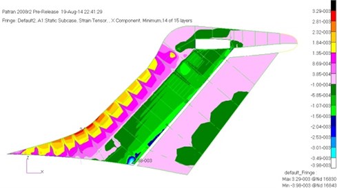
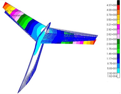
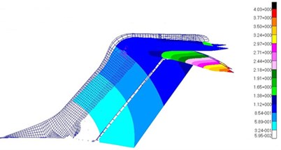
Analysis of static strength and stability on the model of Fig. 4 was conducted, and the results showed that the maximum compressive strain was –3080 με and the maximum tensile strain was 3320 με. They were all located in the connection between the central segment and the outer segment of the skin. The strain decreased from the wing root to tip along spanwise. According to the distribution of strain, we can roughly divide into three sections to optimize. The maximum tensile strain of the vertical tail was 3850 με, which was at the front of the skin. The maximum compressive strain was –3980 με, which was at the connection between rear spar root and the fuselage of the skin. The maximum stress of the beams was 400 MPa, which was located at the connection rear spar and the fuselage. According to the characteristics of the vertical tail, the tail structure can be divided into two parts with the fuselage section and the outer segment to optimize. Fig. 8 and Fig. 9 were respectively the maximum compressive strain of the horizontal tail and vertical tail.
The characteristic of the materials used in the structure was as follows. The allowable tensile strain was 5000 με. The allowable compressive strain was –3800 με. The allowable stress size of aluminum was 350 MPa. In addition, T-tail vibration velocity was required to reach 350 m/s.
Fig. 8The maximum compressive strain of the horizontal tail before optimization
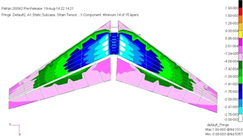
Fig. 9The maximum compressive strain of the vertical tail before optimization
6.1. Preliminary optimization of static strength and stability
Firstly, the preliminary optimization of static strength and stability for T-tail was carried out. According to the optimization principle which the main load-bearing structure was firstly optimized and the secondary structure was later, the thickness and proportion of the skin and beam were optimized firstly, then, the spacing and size of the stringers and web were optimized, and finally the overlay of the rudder skin and the skin around the edge were optimized. And for the main load-bearing components of the horizontal tail and vertical tail, the vertical tail were firstly optimized, and then the horizontal tail was optimized, finally they were combined to optimize.
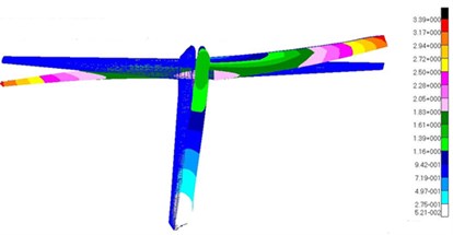
After optimization, the total mass of the horizontal tail and vertical tail structure became 468.1 kg, decreased 14.6 %, the optimization the effect was very significant. Stingers of the vertical tail changed from the original four to six, the number of the horizontal tail web remained changeless. And the maximum compressive strain of the horizontal tail and vertical tail were respectively obtained as shown in Fig. 10 and Fig. 11.
Fig. 10 showed the maximum compressive strain distribution of the horizontal tail. And then it was compared with the maximum compressive strain distribution of the horizontal tail before optimization in Fig. 8. We can find the optimization process greatly reduced the material of the low loading area for the horizontal tail, make the strain along spanwise more uniform. The material utilization was also greatly improved, and the structural weight of the zontal tail was significantly reduced.
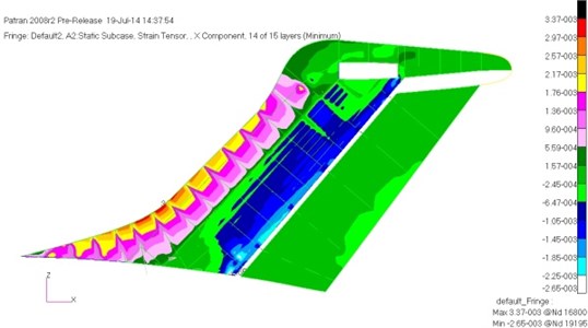
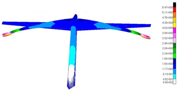
Fig. 11 showed the maximum compressive strain distribution of the vertical tail. It was compared with the maximum compressive strain distribution of the vertical tail in Fig. 9, we can find that the optimization process made skin in the connection area between the vertical tail and the fuselage strengthened. As a result, in the case of tapered stringers, it still met the requirements of stability. While the outer segment skin of the vertical tail was weakened, eventually its strain became more uniform. The strain level of the vertical tail skin was low, but the rear beam had reached a full state of stress. Its maximum stress was 335 MPa. Buckling eigenvalues were also optimized to meet the requirements, the minimum eigenvalue of the horizontal tail was 1.02, and the minimum eigenvalue of vertical tail was 1.18.
Fig. 10The maximum compressive strain of the horizontal tail after preliminary optimization
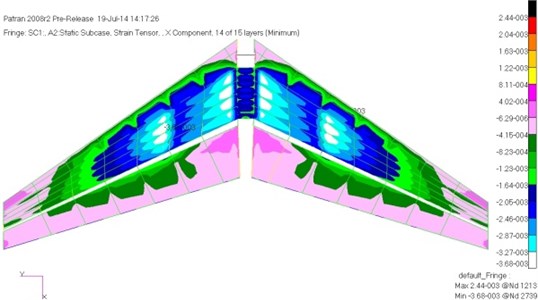
Fig. 11The maximum compressive strain of the vertical tail after preliminary optimization
6.2. MDO after adding vibration constraint
Vibration calculation was carried out for the model after the previous preliminary optimization of static strength and stability. The vibration velocity was 315.7 m/s, and it did not meet the constraint that the vibration velocity was greater than 350 m/s, and therefore we need to further optimize the model to meet the vibration constraints.
ISIGHT software was used to integrate static strength, stability and vibration analysis module of Nastran and the generalized unsteady aerodynamic calculation module of MATLAB. The skin overlay thickness and proportion for the vertical tail and the size of the front and rear beams as well as the influence factors such as dihedral angle, incidence angle and back-sweep angle were selected as optimization variables. The multidisciplinary optimization of static strength, stability and vibration was carried out by means of the higher efficiency SQP. Table 1 showed the change of the top 5 frequencies, vibration velocity and the vertical tail and horizontal tail structure between after preliminary optimization and final optimization. And then, modes of the corresponding frequencies were extracted as shown in Fig. 12.
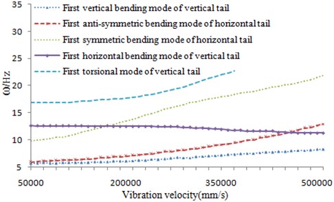
The optimization process made the skin thickness of the vertical tail was slightly thickened, so that the torsional frequency of the vertical tail was increased. As shown in Table 1, the final vibration velocity increased 12.39 %, and the optimized V-g chart and V- chart were shown in Fig. 13 and Fig. 14, respectively. And it led less increase in the weight of the structure, only increased 1.45 % of the total weight. However, it was relative to the original structure, the total weight was reduced by 13.3 %. In addition, the influence factors such as dihedral angle, incidence angle and back-sweep angle has been changed toward a better direction which can be found from the Table 1, Fig. 6 and Fig. 7. The optimization result met the requirements of static strength, stability and vibration design.
Fig. 12Modes of the top 5 orders for T-tail
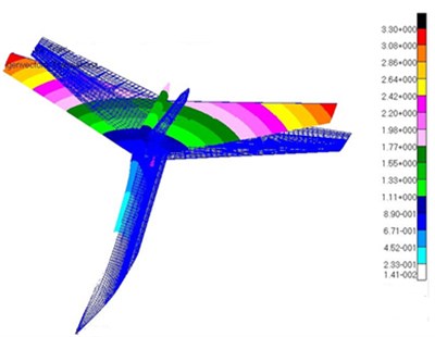
a) Vertical bending mode of the vertical tail
b) Torsional mode of the vertical tail
c) Horizontal bending mode of the vertical tail
d) Anti-symmetrical bending mode of the horizontal tail
e) Symmetrical bending mode of the horizontal tail
When we further observed the optimization results, we can find that the displacement of horizontal tail tip reached 6.88 % of the semi span after optimization, and it exceeded the displacement constraint 5 % of the reference [3]. We can also find that the displacement constraint given by engineering experience was slightly larger, which was not conductive to lightweight of the structure. After fully controlling T-tail vibration characteristics, such displacement constraints can be properly released, so that the weight was further reduced.
Table 1The model comparison before and after the final optimization
Vibration modes | After preliminary optimization | After final optimization |
First vertical bending mode of vertical tail | 4.5976 Hz | 4.6315 Hz |
First torsional mode of vertical tail | 5.122 Hz | 5.3407 Hz |
First horizontal bending mode of vertical tail | 8.4921 Hz | 8.5023 Hz |
First anti-symmetric bending mode of horizontal tail | 10.9824 Hz | 11.0520 Hz |
First symmetric bending mode of horizontal tail | 14.8675 Hz | 14.8812 Hz |
Dihedral angle | 1° | –2.5° |
Lift coefficient | 0.025 | 0.02 |
Back-sweep angle | 35° | 41° |
Vibration speed | 312.4 m/s | 351.1 m/s |
Total weight of vertical tail and horizontal tail | 468.1 kg | 474.9 kg |
Fig. 13V-g diagram after optimization
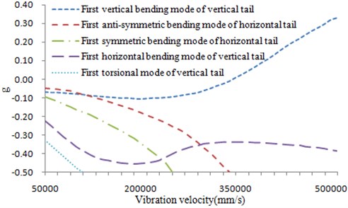
Fig. 14V-ω diagram after optimization
7. Conclusions
This paper firstly sets up a wind tunnel experiment of T-tail to test its aerodynamic characteristics. Then, the experimental results are compared with that of the simulation to verify the reliability of the simulation model. Based on the verified model, the influence factors on T-tail vibration characteristic are analyzed which can be set as the constraint of the subsequent optimization problem. At last, this paper considers the multi-disciplinary optimization problems of T-tail based on static strength, stability and vibration, uses the idea of multi-level optimization, and designs a rational optimization scheme. And then the structure optimization of T-tail is carried out by the proposed scheme. Finally, the mass of T-tail is greatly reduced, and it also meets the design requirements of static strength, stability and vibration. The comprehensive performance is superior, which can also provide some reference to the multi-disciplinary optimization design of other similar structure.
References
-
Fang Baorui Aircraft Aerodynamic Layout Design. Aviation Industry Press, Beijing, Vol. 6, 1997, p. 17-93, (in Chinese).
-
Jennings W. P., Berry M. A. Effect of stabilizer dihedral and static lift on T-Tail flutter. Journal of Aircraft, Vol. 14, Issue 4, 1977, p. 364-367.
-
Rodden W. P. Dihedral effect of a flexible wing. Journal of Aircraft, Vol. 9, Issue 2, 1965, p. 368-373.
-
Emil Suciu. MSC/NASTRAN flutter analyses of T-tails including horizontal static lift effects and T-tails transonic dip. Proceedings of the 1996 MSC World Users’ Conference LosAngeles MSC Software Corporation, 1996, p. 1-7.
-
Land Norman S., Fox Annie G. An experimental investigation of the effects of Mach number, stabilizer dihedral, and fin torsional stiffness on the transonic flutter characteristics of a Tee-tail. NASA TN D-924, 1961.
-
Cbarles L. Rublin, Maynard C. Standford Experimental parametric studies of transonic T-tail flutter. NASA TN D-8066, 1975.
-
Lv Bin, Wu Zhigang, Yang Chao Analysis of T-tail flutter. Engineering Mechanics, Vol. 25, Issue 2, 2008, (in Chinese).
-
Qiu Ju, Sun Qin Flutter analysis of T-tail according to the different supporting stiffness. Aeronautical Computing Technique, Vol. 39, Issue 3, 2009, (in Chinese).
-
Lv Bin, Tan Shengang, Wan Zhiqiang, Yang Chao Optimization design for aeroelastic dynamics of T-tail. Journal of Beijing University of Aeronautics and Astronautics, 2007, (in Chinese).
-
Cai Hengdan, Sun Qin Design optimization for composites T-tail under multi-cases based on MD Nastran. Advances in Aeronautical Science and Engineering, 2012, (in Chinese).
-
Li Liang, Sun Qin Optimization design for T-tail using MSC. Nastran. Aeronautical Computing Technique, 2010, (in Chinese).
-
Chen Guibin, Zou Congqing, Yang Chao Fundamentals of Aeroelastic Design. Bingjing University of Aeronautics and Astronautics Press, Beijing, 2004, (in Chinese).
-
Manohar P. Kamat Structural Optimization: Status and Promise. AIAA, 1993.
-
Vanderplaats G. N. Numerical Optimization Techniques for Engineering Design: With Applications. McGraw-Hill, New York, 1984.
About this article

