Abstract
Concerns about sustainability have led in recent years to develop new structural concepts of timber floor systems which allowed significant performance improvements for strength and stability, while reducing overall costs for a building. All these innovative technologies determine a wide range of opportunities to set up modern timber floors. The components of the building, besides performing resistance and energy efficiency, should provide minimum comfort conditions, expressed in terms of the structural insulation properties and behaviour mode to dynamic actions. Such, timber floor systems must be designed so that actions do not produce vibrations that cause discomfort to users. Generally, in the technical regulations, the permissible vibration level is estimated by limiting modal damping ratio. The paper is addressed to structural designers and presents the experimental procedure and the method to determine the modal damping ratio of a hybrid floor system. The theoretical frequencies which correspond to the energy dissipated by damping can be evaluated on the plot of the frequency response of the hybrid floor system. The methods allow calculating the actual modal damping ratio of the hybrid system by analysing the response of the system subjected to the vibrations.
1. Introduction
1.1. Introduction to topic
The increasing requirement to produce structural systems that meet, in addition to the essential conditions of strength and stability, specific demands of energy efficiency and comfort, led to the design of hybrid systems which present many advantages related to their use. Globally, economic demands and modern technologies in construction operation have solicited the structural designers to come up with optimal solutions that lead to building components with specific prefabricated form, with reduced costs of production and assembly, and with slimmed down execution times. These requirements are applied also for the structural solutions of building timber floors. The structural elements have, sometimes, lower stiffness characteristics and, consequently, a greater vulnerability to the vibrations produced by various operating activities, the phenomenon being commonly met in dynamic actions.
Most problems encountered in practice for floor system have, as a starting point, the resonance phenomenon of one or more vibration eigenmodes produced by dynamic actions occurring during use. The eigenmodes, whose frequencies are in the working frequency range, will always represent a potential hazard under resonance and hence, the need for modal analysis, which studies the vibration modes, modes that characterize the properties of the floor system. Modal analysis can be approached by analytical or experimental. The experimental method is based on experimentally measured modal data, and allows identification of vibration modes of the structure. The results of these experimental studies, allow verification of admission requirements of modal parameters in the limits of technical regulations.
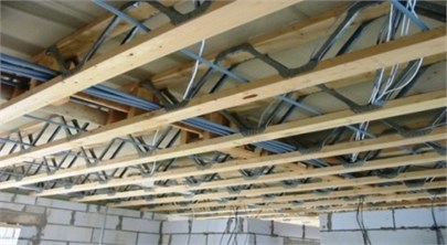
The construction is found extending the use of hybrid structural solutions for floors made of timber and metal components. Timber floor systems using trusses type MiTek, fit in hybrid structural solutions group, Fig. 1, [1]. Trusses of this type are innovative structural elements with good resistance and low energy consumption, performance-enhancing of timber floors through ease of installation, prefabrication and a more rigorous control of the mechanical characteristics of the elements. These floor trusses allow running all services in any direction of the building also.
Fig. 1Floor made of hybrid timber-metal beams
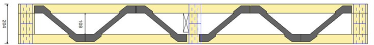
Hybrid trusses made of timber elements fastened with metal joining system are shown in Fig. 2, [2]. PosiStrut systems are modern joining systems used in timber constructions, and are part of multipath metal connectors used to manufacture the floor trusses. The timber planks have cross-section sizes reduced, and the metal lattice strips are made of pre-galvanized steel sheet with a thickness of 1 mm.
Fig. 2Hybrid beams type MiTek with PosiStrut metal joining system
The presented hybrid system of floor, Fig. 1, is currently frequently used for timber construction due to the structural shapes and small sizes of the components, which provide the necessary strength and economic efficiency. The timber-metal hybrid trusses, due to the reduced stiffness, are susceptible to vibrations. The conditions imposed by technical regulations for checking the serviceability limit states (SLS), in particular, the regulations for vibration level, are correctly evaluated if it is used the actual values of the modal parameters in analytical models. These actual values are strongly influenced by the peculiarities of the structural elements (shape, sizes, materials used etc.) and, in the present, the standardised imposed values are overcome by the innovation speed of structural concepts. There are few research studies in identification of the modal parameters, therefore, these particular structural compositions gives no certainty of correct results obtained from analytical models stipulated in technical regulations, to satisfy the criterion of comfort to the vibration effect on users.
In the mechanical testing laboratory of the faculty of Civil Engineering and Building Services from the “Gh. Asachi” Technical University of Iasi, it was developed an experimental research program to proper define behaviour of a floor module made of MiTek hybrid trusses subjected to vibrations, [3, 4]. The lack of detailed experimental studies of these floor systems, both in Romania and internationally, requires the development of the research through laboratory tests, to identify the modal parameters and to develop the solutions of improving the vibration behaviour of floors made of hybrid trusses.
The research purpose presented in paper is to evaluate the real values of modal damping ratio using experimental determined resonance frequency plot. The methodologies of experimental test and theoretical evaluation of the modal damping ratio in the case of a module of floor hybrid system, supported along two edges, are presented.
1.2. State of the art for assessing the vibration behaviour of floor structures
In the literature are found case studies on vibrations behaviour of traditional timber floors that have as the main objectives, in general, verifying the accuracy of the formula given by European design code, [5], and the contribution of the stiffeners, the contribution of the structural plywood from the top, or the contribution of the ceiling plaster sheets from the underside, to the overall stiffness of the floor system, [6, 7]. Another series of experimental research investigates the dynamic response of the new types of floors, recently introduced in the construction market, [8-12]. The results of these experiments have focused on determining the fundamental frequencies, vibration modes and the modal damping ratio, [3].
The European standard EC 5 describes the principles and requirements for safe operation and durability of timber structures. The essential requirements on the limit states of normal operation, in the case of the timber floors, are expressed by the joint slip, limiting values for deflections of beams, and the vibration level. The vibration level should be estimated by measurements or by calculation taking into account the expected stiffness of the member, component or structure, and the modal damping ratio [5]. The chapter 7.3 – “Serviceability limit states. Vibrations” of the EC 5 presents the design rules for action on timber structures, which may reasonably be anticipated to cause vibrations which do not affect the activity in normal conditions or to cause discomfort to occupants. The calculation and verification methodology of requirements is applied to the timber floors whose fundamental frequency () is greater than 8 Hz. For timber floors with a fundamental frequency less than 8 Hz, a special investigation should be made. Frequency components above 40 Hz may be disregarded, [5]. Checks to be made, according to European design code are: deflection control to a concentrated static load and vibration speed control. Limiting speed, , of the response to an ideal unit impulse requires knowing the values of modal damping ratio, . For timber floors, unless other values are proven to be more appropriate, a modal damping ratio of 1.0 should be assumed.
In national technical regulations or in the National Annexes of the EC 5, each country can adopt different values for the modal damping ratio according to certain criteria. An example, [13], which the authors consider it to pinpoint, is norm SIA, [14], according to which the indicative values for the modal damping ratio may be different depending on the type of floor structure:
– 1.0 – timber structures without metal connections;
– 1.5 – timber structures with metal connections;
– 1.0 – timber floor without floating floor;
– 2.0 – timber floor consists of glued elements (tiles) on floating floor;
– 3.0 – timber floor consists of precambered beams and floating floors of planks.
The evaluation methodology of EN 1995-1-1/2004, [5], and the limits of modal damping ratio values presented do not give the confidence that they fit, theoretically, the case study presented in this paper.
1.3. Analytical models to determine the modal damping ratio
Experimental determination of the modal damping ratio of structural systems can be achieved by: 1) Analysing the free vibrations of the system and 2) Studying the resonance response of the system.
1) In the case of free vibration, the modal damping ratio can be determined by measuring two successive amplitudes, and , from the plot of the frequency response of the system, and then calculating the logarithmic decrement, . The modal damping ratio, , is determined using Eq. (1):
2) In the case of studying the resonance responses of the system, the forced vibrations are used for the modal damping ratio determination, by measuring the amplitude and the frequency of vibration at resonance, . At resonance, the vibration amplitude is calculated using the Eq. (2):
where is the fundamental frequency (un-damped natural frequency), is the elastic stiffness of the system, and is modal damping ratio (also known as damping factor, or percentage from critical damping).
When the systems have small damping, the resonance amplitude is calculated using the Eq. (3):
To determine the modal damping ratio, , a harmonic excitation with variable pulsations (angular frequencies) is applied to the system, and then it is measured the resonance amplitude from the plot of the frequency response of the system. The modal damping ratio is evaluated according to Eq. (4), by calculating or experimentally determining the elastic stiffness of the system, , and the fundamental frequency of the system, :
Alternatively if is not assumed small, the relationship becomes:
Fig. 3The plot of the frequency response of the system in resonance
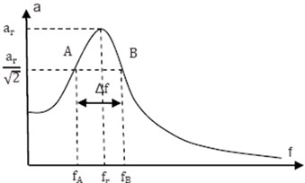
Experimental determination of the resonance response of the system, Fig. 3, allows the identification of the points, A and B, (on the plot of the frequency response of the system in resonance), for which the amplitude of vibration is:
Between frequency band, , delimited by points A and B, the resonance characteristic frequency, , and the modal damping ratio, , there is the dependence expressed by Eq. (7), [15]:
The modal damping ratio is calculated then using the Eq. (8):
2. Experiments in the laboratory
2.1. Hybrid floor model used in experiments
The experimental model is a hybrid floor, with the span of 4000 mm and a width of 2500 mm. The floor, Fig. 4, is supported on two edges. For compiling the floor, it were used five MiTek type beams made of spruce boards with dimensions of 98×48 mm, fastened with PosiStrut joining systems made of galvanized steel with thickness of 1 mm, giving a total truss height of 204 mm and a length of 4000 mm. The floor, at midspan, is reinforced with longitudinal stiffeners made of timber, with cross-section dimensions of 35×97 mm, fixed to each truss individually and perpendicular to them. Between the trusses ends were arranged, too, stiffeners made of timber boards. Over floor trusses were fixed OSB plates, having a thickness of 22 mm.
Fig. 4The experimental model of the hybrid floor
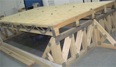
The distance between two consecutive hybrid trusses was 600 mm, the standard spacing for these structural elements. The floor was supported by bearing elements of timber lattice girders type. Timber lattice girders have had a width of 100 mm and overall height of 700 mm. They have also had bracings at the ends and at midspan. The hybrid trusses were supported by girders, directly or through thick rubber pads of 15 mm.
2.2. Description of experimental methodology
Determining the modal damping ratio of system was done by two methodologies. The first methodology was based on free vibrations (Method 1) and the second methodology was based on forced vibrations (Method 2). These are described below.
In the Method 1 (free vibrations), to capture signals were used six accelerometers type KD 35, with sensitivity of 50 mV/g, positioned vertically. With each of the six accelerometers, five measurements were performed, in all cases an accelerometer has been kept in the centre or in the marginal area as reference. Two sets of experimental measurements were made.
Data acquisition system has been type-National Instruments using LabVIEW software. Rubber hammer blows are the source of excitation, Fig. 5.
The recordings were made simultaneously for the 6 channels over a total period of 60 s with a sampling period (time difference between the two readings) of 0.001 s (1000 readings/s). ARTeMIS Test (version 2011) was used to model the experimental tests. ARTeMIS Extractor (v. 2011) was used for dynamic identification of the floor hybrid system which was done by applying the following techniques: EFDD and SSI-UPC (Enhanced Frequency Domain Decomposition and Un-weighted Principal Component). Fourier analysis was conducted in 1024 averaging points. Vibration modes of the hybrid system were analysed up to the frequency of 50 Hz. The modal damping ratio was calculated using Eq. (1) in logarithmic decrement technique from the logarithmic envelope of the correlation function. The estimation is performed by using a linear regression technique.
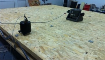
In the Method 2 (forced vibrations), vibrations capture was done with a seismic velocity transducer, Kinemetrics SS1 model, with a very high sensitivity (345 V/m/s), connected to a data acquisition system that converts the analogue signal into a digital signal, recorded and stored on the hard disk of a computer. The used excitation source was an electro-dynamic vibration generator, Fig. 6. The vibration generator is connected to an amplifier that is controlled by an oscillator of sine waves with variable frequencies. Step amending the curves of resonance frequency was 0.01 Hz. A total of seven resonance curves have been identified related to the positions of excitation source. The modal damping ratio was calculated based on the resonance curves using Eq. (4).
Fig. 5Experimental test in the first methodology (free vibrations)
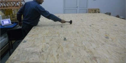
Fig. 6Experimental test in the second methodology (forced vibrations)
3. Results and discussion
The time domain response of the hybrid system to the action of free vibrations (Method 1) is shown in Fig. 7, and the results are presented in Table 1. There are presented also the standard deviations of the results.
Fig. 7The time domain response of the hybrid system
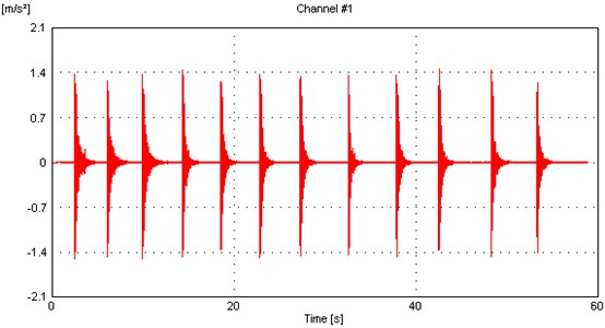
In this method, the first mode of vibration is identified in the case when rubber hammer blows have been applied all over the hybrid floor system.
For the tested hybrid system, MAC matrices (Modal Assurance Criterion) between FDD-EFDD, FDD-SSI and between EFDD-SSI give values greater to 0.9 which, in practice, are commonly recognized as acceptable for the correspondence between two mode shapes. The MAC values between the actual vibration mode shapes and the estimates obtained after removing the harmonic component give good correlations and clearly indicate that the vibration eigenmodes of the system are identified. In all experimental tests, the accuracy of the forms and the precision of the eigenmodes frequencies are very good.
The lowest value of the modal damping ratio obtained in FFT analysis (Fast Fourier Transform) highlights that, in the third vibration mode of the floor system frequency response, the maximum energy of the vibrations are dissipated. It is observed that the modal damping ratio increases with the excitation level, and its accurate calculation, using dynamic identification methods with unknown excitation, is reduced.
Table 1The modal damping ratio results using free vibrations method
Test 1 | ||||
Mode | Frequency [Hz] | Std. frequency [Hz] | Damping ratio [%] | Std. damping ratio [%] |
EFDD Mode 1 | 16.49 | 0.1042 | 1.833 | 0.9396 |
EFDD Mode 2 | 21.01 | 0.5585 | 2.28 | 0.6088 |
EFDD Mode 3 | 28.39 | 0.05512 | 1.145 | 0.08036 |
EFDD Mode 4 | 39.44 | 1.002 | 2.469 | 0.6352 |
SSI-UPC Mode 3 | 28.29 | 0.0276 | 1.362 | 0.06161 |
SSI-UPC Mode 4 | 40.09 | 0.0002474 | 2.959 | 0.001732 |
Test 2 | ||||
Mode | Frequency [Hz] | Std. frequency [Hz] | Damping ratio [%] | Std. damping ratio [%] |
EFDD Mode 1 | 16.45 | 0.03345 | 1.709 | 0.4209 |
EFDD Mode 2 | 21.02 | 0.5871 | 1.973 | 0.7114 |
EFDD Mode 3 | 28.41 | 0.04284 | 1.155 | 0.1307 |
EFDD Mode 4 | 39.82 | 1.001 | 3.115 | 1.11 |
SSI-UPC Mode 3 | 28.38 | 0.002049 | 1.076 | 0.0213 |
SSI-UPC Mode 4 | 41 | 0.01691 | 1.627 | 0.09233 |
The modal damping ratios, for the fundamental mode of vibration, according to the procedure of Method 1, have values between 1.709 % and 1.833 %. Therefore, an average value of 1.771 % for modal damping ratio can be assigned to the hybrid floor system.
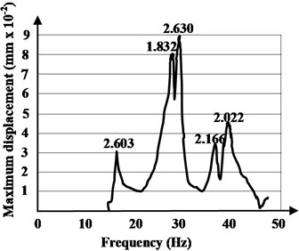
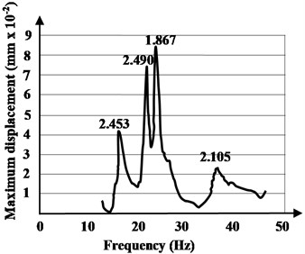
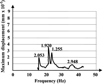
In Method 2, using forced (induced) vibrations, the resonance frequency of the hybrid floor system have been obtained. The excitation source has been placed in seven different positions on the floor surface. Dynamic displacements were obtained by integrating the velocity of the seismometer. The experimentally identified mode shapes are shown in Figs. 8-10. In the plots, each peak identifies a natural frequency of the tested hybrid structure and the frequencies at which the response amplitude is a relative maximum are the frequency response of the hybrid floor system in resonance. There are some losses from cycle to cycle and these are damping.
Fig. 8The resonance amplitude curves with source placed in the first quarter of the hybrid floor system and in opposite position
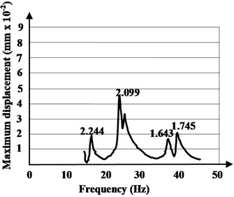
a) Quarter 1
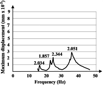
b) Opposite quarter 1
According to the provisions presented in the procedure of the paragraph 1.3, and applying the Eq. (4), the modal damping ratios are evaluated. The modal damping ratios, for the fundamental mode of vibration, according to the procedure of Method 2, have values between 2.034 % and 2.603 %, with an average value of 2.318 %.
A key issue in identifying actual modal damping ratio of a hybrid system is to decide the appropriate experimental methodology. In the Method 1, where the excitation force is not measured, the modal damping ratio tends to be less reliable than those obtained from tests where the excitation force is measured. This is because the lack of force measurement requires a number of assumptions to be made to enable extraction of modal properties, and these assumptions lead to errors.
Fig. 9The resonance amplitude curves with source placed in the second quarter of the hybrid floor system and in opposite position
a) Quarter 2
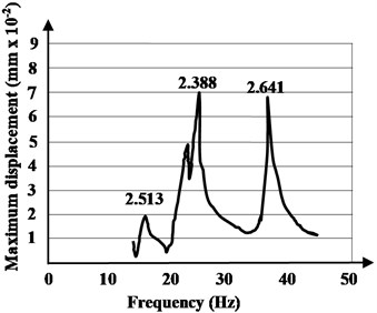
b) Opposite quarter 2
Fig. 10The resonance amplitude curves with source placed in the middle of the hybrid floor system and in opposite position on the system edge and end
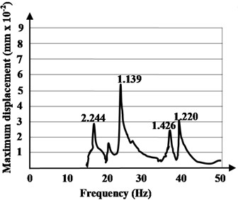
a) Middle
b) Opposite middle – on the system edge
c) Opposite middle – on the system end
The Method 2 evaluates experimentally the actual modal damping ratio of the hybrid system, studying the resonance response of the system. The vibration modes in a resonance frequency band are obtained using a source which provides excitations in waveforms and allows controlling the frequency content of the excitation.
4. Conclusions
Dynamic parameters of the hybrid floor structures are of high importance since they govern how the structures respond to seismic, and in-service human-induced dynamic vibration. Natural frequencies and modal damping ratio of a building element/structure can be evaluated using modal testing, as verification to calculation.
The purpose of the experiments was to determine the damping ratio of the structure (so as it is designed) to highlight the errors that can occur in design of these types of hybrid floor systems.
Modal testing is based on dynamics of structural systems which exhibit vibrations. Experimental determination of the modal damping ratios of structural systems have been achieved by analysing the free vibrations of the system (Method 1) and studying the resonance response of the system (Method 2).
The increases of modal damping ratios for the presented hybrid floor system, obtained experimentally in both methods, show that the standard prescribed value does not comply with actual modal damping of this type of hybrid structures. The actual modal damping ratios are correct, as evidenced by the experimental measurements, and their increases are due to the fact that metal joining systems are sources of energy dissipation in the vibrating hybrid structure. The energy loss can take place through frictional effects between different components and friction within materials, especially in timber components.
The results for the actual modal damping ratios determined using the resonance response of the system, (Method 2), are more credible, because the experimental methodology overcomes the problems with impact testing used in Method 1 where the chosen grid could not be dense enough to describe all of the likely mode shapes of the hybrid floor system in sufficient details.
Analyzed hybrid floor system consists of individual members that have a reduced rigidity, and this leads to the idea that it is not stiff enough to properly respond to the dynamic vibrations. The imposed approach by serviceability limit states check determines increasing the area of cross section of wooden elements, or changing angle and dimensions of the metal connectors. But only the natural frequency, modal mass and mode shape are dependent on the dimensions, mass and stiffness of the structure. Damping depends mainly on the finishes of the structure. It is relevant therefore, in after measurement results, that the levels of modal damping ratios, which are established at the concept design stage, must be appropriately evaluated, paying particular attention to each type of structural floor system used and their fabrication technology, and for every anticipated usage of the floors.
The results highlights that the unique value of modal damping ratio for timber structures prescribed in European Standard EN 1995-1-1, [5], is not suitable for the shapes of new developed hybrid floor systems and an appropriate value will generally have to be assumed based on testing.
The performance statements of construction products usually contain technical data which refer more to the resistance essential requirement. In the case of hybrid components used for structural elements sensitive to vibrations, the designer must comply with the performance requirements in service and these are related to modal parameters including damping ratios. The authors also consider that, for a sustainable design of buildings realised with timber-based-products, the regulated value of modal damping ratio must be refined according to the type of structural system used. The future researches must be developed to standardise the actual modal parameters of the new hybrid timber floor systems.
References
-
http://www.mitek.com
-
http://www.mitek.ro/posi-strut/
-
Corduban A. Modern Timber Structures for Sustainable Development. Ph.D. Thesis, Gh. Asachi Technical University of Iasi, Romania, 2013.
-
Gavriloaia C., Corduban C., Isopescu D., Țăranu N., Budescu M. Calibration of a wooden floor calculation model based on the experimentally determined dynamic characteristics. 14th Symposium on Experimental Stress Analysis and Materials Testing, Vol. 601, 2014, p. 211-214.
-
EN 1995-1-1/2004, Eurocode 5: Design of Timber Structures – Part 1-1: General – Common Rules and Rules for Buildings.
-
Page A. Vibrations on I-Joist Timber Floors for Domestic Occupancy. Final Report, Trada Technology Limited, 2006.
-
Zhang B. Experimental Investigations of Vibrational Performance of Floors with Metal Web Joists and Enhancement Using Strong-Back Bracings. Centre for Timber Engineering, School of Engineering and the Built Environment, Napier University, Edinburgh, UK, 2008.
-
Crespo J. A. Measurements of Vibrations in Wooden Floors Induced By Walking. Bachelor’s Dissertation, Lund University, Lund, Sweden, 2009.
-
Ejenstam J., Floden O. Vibration Analyses of a Wooden Floor-Wall Structure – Experimental and Finite Element Studies. Master’s Dissertation, Lund University, Lund, Sweden, 2011.
-
Hu L., Gagnon S. Controlling cross-laminated timber (clt) floor vibrations: fundamentals and method. Proceedings of WCTE, World Conference of Timber Engineering, Auckland, New Zeeland, Engineering Technical Issues 2, 2012, p. 269-275.
-
Lukaszewska E., Fragiacomo M. Static and dynamic (vibration) performance of composite beams with prefabricated concrete slab. World Conference on Timber Engineering, WCTE, Aukland, New Zeeland, 2010.
-
Weckendorf J., Smith I. Dynamic characteristics of shallow floors with cross laminated timber spines. Proceedings of WCTE, World Conference of Timber Engineering, Auckland, New Zeeland, 2012, p. 176-186.
-
Angeli A. Corso avanzato di projettazione per edifici di legno: statica, seismica e cantiere. Cortaccia (BZ), Rothoschool Corsi, 2011, p. 76-92.
-
SIA 265/2003, Swiss Society of Engineers and Architects SIA. Standard SIA 265: Timber Structures.
-
Butterworth J., Lee J. H., Davidson B. Experimental determination of modal damping from full scale testing. The 13th World Conference on Earthquake Engineering, Vancouver, B.C., Canada, 2004.
About this article

This research has been conducted in the Civil Engineering Research Centre of Faculty of Civil Engineering and Building Services, “Gh. Asachi” Technical University of Iasi, Romania. The authors would like to thank the MiTek Romania for their supports and contribution in preparing the hybrid floor system.
